Keywords
|
| MIMO, LTE, QPSK, BPSK, QAM |
INTRODUCTION
|
A. MULTIPLE INPUT MULTIPLE OUTPUT
|
| MIMO wireless communication refers to the transmissions over wireless links formed by multiple antennas equipped at both the transmitter and receiver. The key advantages of employing multiple antennas lie in the more reliable performance obtained through diversity and the achievable higher data rate through spatial multiplexing. |
| MIMO technology has attracted attention in wireless communications, because it offers significant increases in data throughput and link range without additional bandwidth or transmit power. It achieves this by higher spectral efficiency (more bits per second per hertz of bandwidth) and link reliability or diversity (reduced fading). Because of these properties, MIMO is an important part of modern wireless communication standards such as IEEE 802.11 (Wi-Fi), 4g, 3GPP Long Term Evolution, WiMAX and HSPA+. |
B. PRINCIPLE OF MIMO
|
| MIMO is based on the principle of diversity and spatial multiplexing. The key advantages of employing multiple antennas lie in the more reliable performance obtained through diversity and the achievable higher data rate through spatial multiplexing. |
II. PROJECT WORK
|
A. MU-MIMO
|
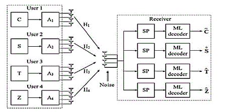
| Multi-user MIMO can leverage multiple users as spatially distributed transmission resources, at the cost of somewhat more expensive signal processing. In comparison, conventional, or single-user MIMO considers only local device multiple antenna Dimensions. Multi-user MIMO algorithms are developed to enhance MIMO systems when the number of users, or connections, numbers greater than one (admittedly, a useful concept). Multi-user MIMO can be generalized into two categories: MIMO broadcast channels (MIMO BC) and MIMO multiple access channels (MIMO MAC) for downlink and uplink situations, respectively. Single-user MIMO can be represented as point-to-point, pairwise MIMO. To remove ambiguity of the words receiver and transmitter, we can adapt the terms access point and user. An AP is the transmitter and a user is the receiver for downlink environments, whereas an AP is the receiver and a user is the transmitter for uplink environments. Homogeneous networks are somewhat freed from this distinction |
B. SPACE TIME CODING FOR MIMO-OFDM
|
| A space–time code (STC) is a method employed to improve the reliability of data transmission in wireless communication systems using multiple transmit antennas. STCs rely on transmitting multiple, redundant copies of a data stream to the receiver in the hope that at least some of them may survive the physical path between transmission and reception in a good enough state to allow reliable decoding. Space time codes may be split into two main types: |
| ? Space time trellis codes (STTCs) distribute a trellis code over multiple antennas and multiple time-slots and provide both coding gain and diversity gain. |
| ? Space time block code (STBC) act on a block of data at once (similarly to block codes) and provide only diversity gain, but are much less complex in implementation terms than STTCs. |
| The MIMO channel matrix H corresponding to nt transmit antennas and nr receive antennas can be represented by an nr × nt matrix: |
 (1) (1) |
| Where the ji-th element, denoted by ht j,i, is the fading gain coefficient for the path from transmit antenna i to receive antenna j. We assume perfect channel knowledge at the receiver side and the transmitter has no information about the channel available at the transmitter side. Given the receive matrix Y the ML-detector decides for the transmit matrix S with smallest Euclidian distance d2.The structure of the MIMO solution is very similar to that of a conventional wireless OFDM physical layer, except that the carrier frequency is changed based on the time-frequency code. In addition, other modifications have been made to reduce the area and size. |
| Multiuser orthogonal frequency-division multiplexing (MB-OFDM) is one of ultra-wideband (UWB) radio standards, which provides high-speed connectivity in a wireless personal area network (PAN) with specification of the data rates from 53.3 to 480 Mbps . Due to the high data rates, the MB-OFDM standard requires to process large amount of computations in very short time; its modem has to compute one symbol that consists of 165 complex numbers in every 312.5 ns. Even though its performance requirement results in large hardware complexity, a low power design with small chip size is absolutely essential for applying this technology to portable handheld devices. |
| In MIMO, the standard specification defines a sampling frequency of 528 MHz Such high frequency is problematic when we use it as a system clock speed; it consumes too much power and it is hard to implement due to timing constraints. Therefore, parallel architectures have been proposed in an effort to reduce power consumption as well as to relax timing constraints. Exploiting parallelism with -way parallel architecture enables to keep throughput constraint at - time’s lower clock speeds, whereas it may increase the hardware resources by a factor. Despite of the increased hardware resources, it is possible to reduce power consumption as well as to relax timing constraints due to two reasons. |
| First, X way parallel architecture compensates for X times longer gate delays. Therefore, the parallel hardware can operate at reduced supply voltages and consequently consume less power. |
| First, X way parallel architecture compensates for X times longer gate delays. Therefore, the parallel hardware can operate at reduced supply voltages and consequently consume less power. |
| It is possible to share hardware resources among independent parallel data-paths. For example, a packet synchronizer with the cross correlation scheme requires a single set of shift registers which holds only one MIMO symbol. Four parallel data-paths can share an output of a single coefficient generator at cost of negligible performance loss in a carrier frequency offset (CFO) compensation unit. |
C.SIGNAL GENERATION
|
| The number of subcarriers N, the bandwidth of each subcarrier 1/NT , the bandwidth of the system |
| B ≈1/T , and the length of the cyclic prefix Δ are all important parameters in the design of an OFDM system. |
| First, the length of the cyclic prefix should be chosen to be a small fraction of the OFDM symbol length to minimize the loss of SNR (or data rate) . Because the size of the cyclic prefix is directly related to the delay spread τ of the channel a rule of thumb is that the length of the OFDM symbol |
| NT>> τ or, equivalently, the number of subcarriers N>> τB . However, if the OFDM symbol length NT is too long the ICI caused by Doppler spreading in the fading channel can become performance limiting. If the intercarrier spacing 1/NT is chosen much larger than the maximum Doppler frequency fd, the system is relatively insensitive to the Doppler spread and the associated ICI. Therefore, the number of subcarriers should satisfy fd << 1/NT or equivalently.N<<B/fd The above two constraints result in the following restriction on the number of subcarriers |
 (2) (2) |
| Equation (2) also states a requirement on the delay- and Doppler-spread of the physical channel for proper design of an OFDM system. The far left hand side and the far right hand side also lead to ,fdτ << 1,which means that the more the channel is under spread, i.e., the more correlated the channel is in either time or frequency, the easier it is to find a exact number of subcarriers N. |
D.CODING
|
| Error control coding is an essential part of an OFDM system for mobile communication. OFDM in a fading environment is almost always used with coding to improve its performance and as such is often referred to as Coded OFDM. For an uncoded OFDM system in a frequency selective Rayleigh-fading environment, each OFDM subcarrier has a flat-fading channel. Accordingly, the average probability of error for an uncoded OFDM system is the same as that for a flat-fading single-carrier system with the same average geometric mean of the subcarriers’ SNRs. |
| Just as we can introduce time diversity through coding and interleaving in a flat-fading single-carrier system, we can introduce frequency diversity through coding and interleaving across subcarriers in an OFDM system .However, since OFDM in itself does not increase the system bandwidth it can never introduce frequency diversity on flat fading channels. With coding and interleaving across subcarriers, the strong subcarriers help the weak ones. Over a single OFDM signal, we cannot guarantee that the interleaved subcarriers are all independent. In this we find that the achievable frequency diversity in a OFDM system is limited by the number of resolvable independent paths in the channel impulse response. One heuristic explanation is as follows. Coding diversity requires independent SNRs on each path to get the full diversity of the code. |
| In an OFDM system the SNRs of different subcarriers are usually correlated because the channel length is small compared to the OFDM symbol length, NT. How correlated the subcarriers are depends on the number of resolvable taps. In the extreme case of a one-tap channel, the SNR on all the subcarriers is the same. |
| So regardless of the interleaving or power of the code interleaving in frequency will not increase the diversity. As the number of taps in the channel increases the correlation between subcarriers decreases but they will never be totally independent. |
| h1j,i = h2j,i = · · · = hNj ,i = hj,i, i = 1, 2, · · · , nt, j = 1, 2, · · · , nr. -11 |
| Next, a nt × nt code distance matrix A is defined as |
 (3) (3) |
| Where the superscript H denotes the Hermitian (transpose conjugate) of a matrix. A is a nonnegative definite Hermitian matrix, since A = AH and the Eigen values of A are nonnegative real numbers .Therefore, there exists a unitary matrix U and a real diagonal matrix _ such that |
 (4) (4) |
| The rows of U, {u1, u2, · · · , unt} are the eigenvectors of A. The diagonal elements of, denoted as_i, i = 1, 2, · · · , nt are the eigenvalues of A. Let r denote the rank of the matrix A. Then there exist real, nonnegative eigenvalues v1,v2· · ·, vr. With |
| hj = [hj,1, hj,2, · · · .hj,nt ]T and j,i = hj · ui 1 can be rewritten as |
 (5) (5) |
| Substituting in we obtain |
 (6) (6) |
| Inequality is an upper bound on the conditional pair wise error probability expressed as a function of |_j, i|. From two most important parameters of a STC can be defined: |
| The diversity gain is equal to rnr. It determines the slope of the mean PEP over SNR curve. It is an approximate measure of a power gain of the system with space diversity compared to system without diversity measured at the same error probability value. |
| The coding gain is (Or i=1 _i)1/r. It determines a horizontal shift of the mean PEP curve for a coded system relative to an uncoded system with the same diversity gain. To minimize the PEP, it is preferable to make both diversity gain and coding gain as large as possible. Since the diversity gain is an exponent in the error probability upper bound, it is obvious that in the high SNR range achieving a large diversity gain is more important than achieving a high coding gain. |
E. PERFORMANCE ANALYSIS
|
| To understand the properties of the STC, we will give an overview on the performance analysis first developed by Tarokh and Vucetic . For the performance analysis of STCs it is important to evaluate the pair wise error probability (PEP). The pair wise error probability P(S,S) is the probability that the decoder selects a codeword |
| ˆs= [ˆs1, ˆs2, · · · , ˆsN], when the transmitted codeword was in fact |
| S = [s1, s2, · · · , sN] ≠ ˆS. Assuming that the matrix H = [h1, h2, . . . , hN] is known, than the conditional pair wise error probability is given as: |
 (7) (7) |
| Where d2H(S,S^) is given by |
 (8) (8) |
| Where Es is the energy per symbol at each transmit antenna, N0 is noise power spectral density and Q(x) is the complementary error function defined by: |
 (9) (9) |
| By applying the bound |
 (10) (10) |
| The PEP 8 in 6 becomes |
 (11) (11) |
F. ERROR PROBABILITY FOR SLOW FADING CHANNELS
|
| If slow fading is assumed, the fading coefficients are assumed to be constant during Ns symbols and vary from one symbol block to another, which means that the symbol period is small compared to the channel coherence time. Since the fading coefficients within each frame are constant the superscript t of the fading coefficients can be ignored. |
G. MANY ANTENNAS
|
| Many Antennas is a smart antenna technique, which overcomes the performance limitation of single user MIMO techniques. In cellular communications, the number of the maximum considered antennas for downlink is 2 and 4 to support LTE and IMT-A requirements, respectively. Since the available spectrum band will probably be limited while the requirement of data rate will continuously increase in beyond IMT-A to support the mobile multimedia services, it is highly probable that the number of transmit antennas at the base station must be increased up to 8 ~ 64 or more.The installation of many antennas at single base stations can have many challenges so it requires to develop several high technologies: new SDMA, new beamforming algorithm and new antenna array. New SDMA: MU-MIMO, Network MIMO (COMP), Remote radio equipments New beamforming: linear beamforming such as MF, ZF and MMSE and nonlinear beamforming such as THP, VP, and DPC New antenna array: direct, remote and wireless antenna array Direct antenna array: linear and 3d phased array, new structure array, and dynamic antenna array Remote and wireless antenna array: distributed antenna array and cooperative beamforming. |
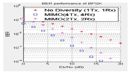
| From fig.3. with MIMO BER is reduced considerably. When number of antennas increased BER will be reduced considerably. Diversity gain can be increased by increasing antennas. |
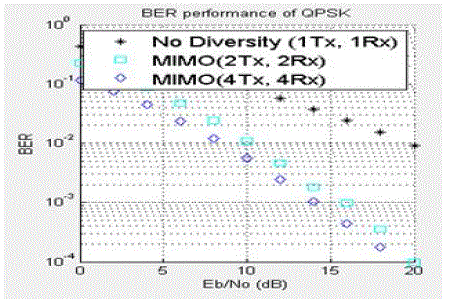
| From fig.4. with QPSK modulation the BER will be increased without diversity.When number of antennas increased BER will be reduced considerably. |
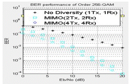
| From fig.5.without MIMO we will receive worst diversity due to high end mapping.When we use maximum antennas then only BER will be reduced considerably. |
IV. CONCLUSION
|
| In this paper we analyze the performance of MIMO with various modulation schemes. As a result of the use of multiple antennas, MIMO wireless technology is able to considerably increase the Quality of service of a given channel. By increasing the number of bits mapped (mapping order) and number of antennas it is possible to get same QoS through spatial diversity with every pair of antennas added to the system. |
Figures at a glance
|
 |
 |
 |
 |
 |
| Figure 1 |
Figure 2 |
Figure 3 |
Figure 4 |
Figure 5 |
|
| |
References
|
- A. Stamoulis, N. Al-Dhahir and A. R. Calderbank, “Further results on interference cancellation and space-time block codes," in Proc. 35th Asilomar Conf. Signals, Syst. Comput., pp. 257-262, Oct. 2001.
- A. Scaglione, P. Stoica, S. Barbarossa, G. Giannakis, and H. Sampath, “Optimal designs for space-time linear precoders and decoders," IEEE Trans. Signal Process., vol. 50, no. 5, pp. 1051-1064, 2002.
- H. Sampath and A. Paulraj, “Linear precoding for space-time coded systems with known fading correlations," IEEE Commun. Lett., vol. 6, no. 6, pp. 239-241, June 2002.
- J. Kazemitabar and H. Jafarkhani, “Multiuser interference cancellation and detection for users with more than two transmit antennas," IEEE Trans. Commun., vol. 56, no. 4, pp. 574-583, Apr. 2008.
- Y. Wu and A. R. Calderbank, “Code diversity in multiple antenna wireless communication," in Proc. IEEE International Symp. Inf. Theory, Toronto, Canada, July 2008.
- J. Kazemitabar and H. Jafarkhani, “Performance analysis of multiple antenna multi-user detection," in Proc. 2009 Workshop Inf. Theory Applications, Feb. 2009.
- C. W. Tan and A. R. Calderbank, “Multiuser detection of Alamouti signals," IEEE Trans. Commun., vol. 57, no. 7, pp. 2080-2089, 2009.
- F. Li and H. Jafarkhani, “Multiple-Antenna Interference Cancellation and Detection for Two Users Using Precoders," IEEE J. Sel. Topics Signal Process., vol. 3, no. 6, pp. 1066-1078, Dec. 2009.
- M. S. Al-Janabi, C. C. Tsimenidis, B. S. Sharif and S. Y. Le Goff, “Bit and Power Allocation Strategy for AMC-based MIMO-OFDMA WiMAX Systems”, IEEE 6th International Conference on Wireless and Mobile Computing, Networking and Communications, pp 575-579, 2010.
- S. Ajey, B.Srivalli and G.V.Rangaraj, “On Performance of MIMO-OFDM Based LTE Systems”, International Conference on Wireless Communications and Sensor Computing, pp 1-5, 2010.
|