Radiation fields of the offset paraboloidal reflector illuminated by a prime focus feed and tilted feed employing the physical optics method. A set of curves generated by the optimum orientation of the axis of the feed for maximum antenna efficiency as a function of the offset angle β and the half angle α subtended by the reflector at its focus. A comparison on efficiency and side lobe levels is presented for different exiting angles of the feed.
Keywords |
| offset paraboloidal reflector, prime-focus, Side-lobe, Physical optics, cross polarization, rotational
symmetric feed pattern, deviation angle. |
INTRODUCTION |
| Some scientists [1] – [4] have explored the various aspects of the radiation characteristics of the offset paraboloids.
In another publication [5] Rudge and Adatia presented a detailed survey in this topic. Jamnejad-Dailami and Rahmat-
Samii [6] highlighted that the side-lobe levels in the symmetric plane could be improved by orienting the axis of the
prime-focus feed along the direction of an incident ray, for which the reflected ray from the antenna passed through the
center of the projected aperture. This improvement was found to be, to some degree, at the expense of the co-polar sidelobe
levels and the peak cross polarization in the asymmetric plane. However the effect of feed orientation on the
reflector efficiency was not indicated. |
ANALYSIS |
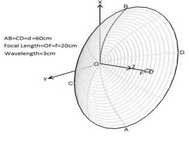
| The geometry of the antenna is shown in Fig.1. For estimating the secondary fields, three Cartesian coordinate
systems with their associate spherical coordinate [7]. |
 |
NUMERICAL RESULTS |
| From equation (3) the antenna efficiency was calculated numerically for different orientations of the feed. The
optimum deviation angle of the feed axis from the cone one, to achieve the maximum efficiency, is plotted in Fig. 2 |
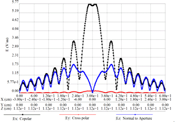
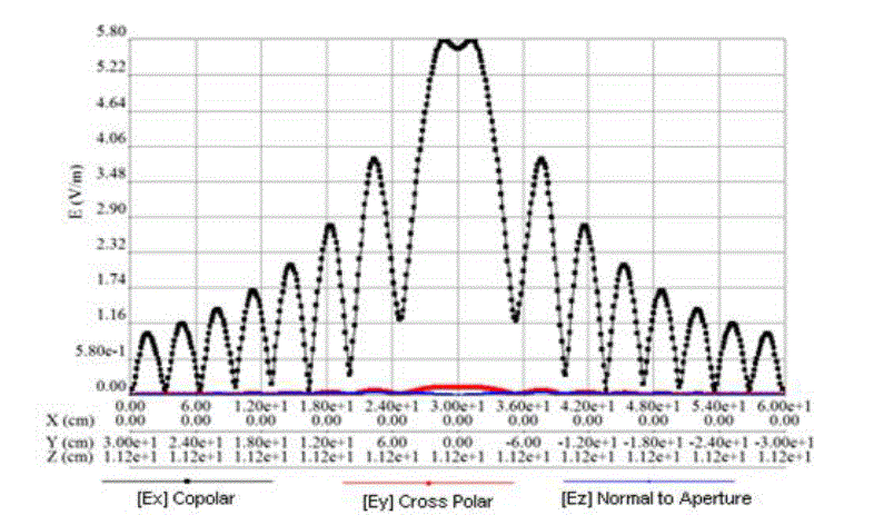
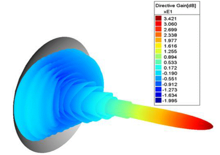
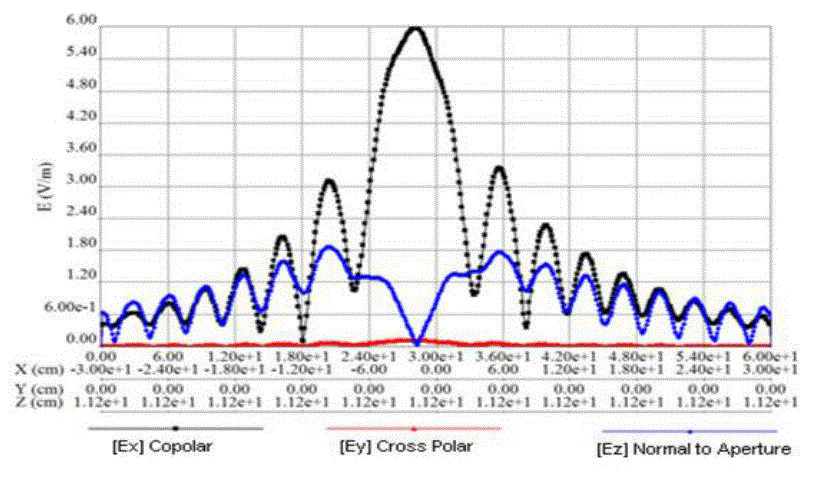
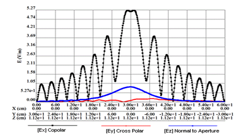
| As a function of half angle α for different offset angles β. Fig.2, Fig.3 & Fig.4 are the results of prime focus
paraboloid (feed is at focus). For this case Directive Gain = 34.21 dB. Feeding is done such a way that the co-polar
component of the aperture fields is in x-direction. Therefore the cross polar component of aperture fields are in Ydirection.
The Z-directed fields on the aperture are non-radiating fields (not important field component). |
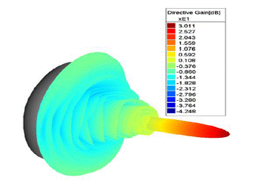
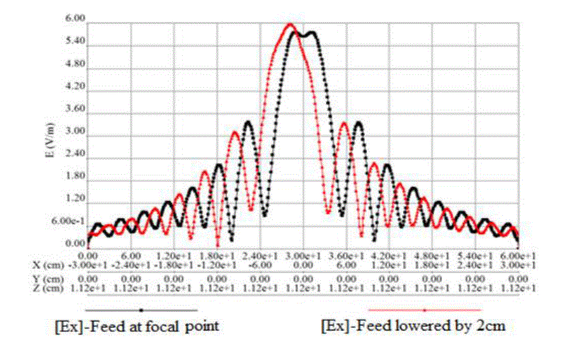
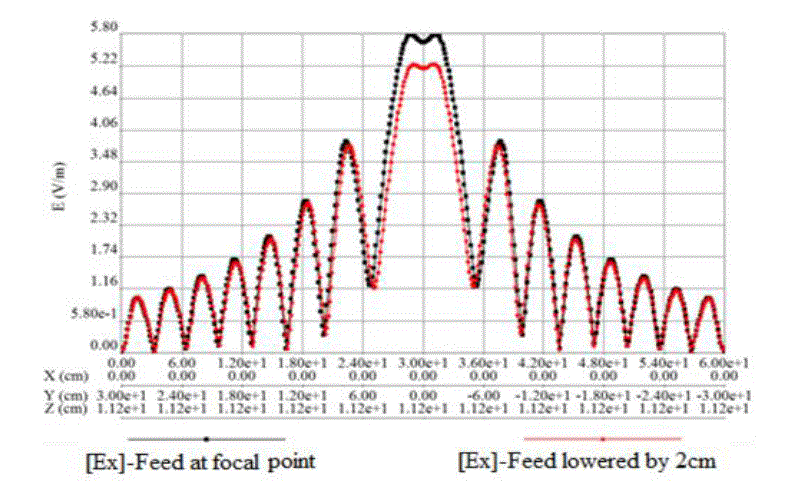
| Fig.5, Fig.6 & Fig.7 are results of feed lowered by 2cm. For this case Directive Gain = 30.11 dB. The co-polar fields
(Ex) of Fig.2 and Fig.5 are shown in Fig.8 to highlight the effect of the feed displacement (E = plane, ϕ = 0 deg.). |
| The co-polar fields (Ex) of Fig.3 and Fig.6 are shown in Fig.9 to highlight the effect of the feed displacement (H =
plane, ϕ = 90 deg). If we observe Fig.2, Fig.3 and Fig.5, Fig.6 the cross polar component fields (Ey) are very small
compared to the co-polar fields (Ex). |
CONCLUSION |
| It can be concluded that among the three cases considered the reduction of side-lobes in the symmetric plane is more
significant when the feed is along the central aperture direction. As pointed out in the optimum side-lobe levels in the
symmetric plane. The maximum deterioration of the peak cross polar level, encountered in the asymmetric plane, is
about 1.2dB in the different cases considered. The peak cross-polar level can be controlled by employing the matched
field method. Therefore the optimum overall side-lobe level can be expected, especially for reflectors of smaller F/D
ratio, by illuminating the reflector with a tilted matched feed. |
ACKNOWLEDGMENT |
| We would like to express our thanks to the department of ECE and Management of KL University for their support and
encouragement during this work. We also express out thanks to the department of ECE of CMJ University for
providing facilities for the research work. Further author like to express sincere thanks to Prof. N. Venkatram,
Associate Dean, Electrical Sciences, KL University for providing R&D facilities at KL University to carry out this
work. |
Figures at a glance |
 |
 |
 |
 |
 |
| Figure 1 |
Figure 2 |
Figure 3 |
Figure 4 |
Figure 5 |
 |
 |
 |
 |
| Figure 6 |
Figure 7 |
Figure 8 |
Figure 9 |
|
|
| |
References |
- J.S. Cook, E.M. Elam, and H. Zucker, ?The open Cassegrainian Antenna - part 1: Electromagnetic design and analysis, ? Bell Syst, Tech J.,vol.44, pp.1255-1300, Sept. 1965.
- W. Rudge, ?Multiple âÃâ¬Ãâbeam antennas: Offset reflectors with offset feeds, ? IEEE Trans. Antennas Propagat., vol. AP-23, pp.317-322, May1975.
- R. Mittra, Y. Rahmat - Samii, V. Galindo - Isreal, and R. Norman, ? An Efficient technique for the computation of vector secondary patterns ofoffsetparaboloid reflectors, ? IEE Trans. Antenna Propagat., vol. AP-27, pp.294-304, May 1979.
- S. M. Tun and P.J. B. Clarricoats, ? Single offset reflector with a matched âÃâ¬Ãâfeed array.? In IEEE Int. Antennas Propagat. Symp. Dig., vol. 1. June1984, pp. 486-486
- W. Rudge and N. A. Adatia, ? Offset parabolic reflector antennas: A review, ? Proc. IEEE, vol.66, no. 12, pp1596-1618, Dec. 1978.
- V. Jamnejad - Dailami and Y. Rahmat - Samil, ? Some important geometrical features of conic-section-generated offset reflector antennas,?IEEE Trans. Antennas Propagate., vol. pp. 952âÃâ¬Ãâ57, Nov. 1980.
- D. J. Bem, ?Electric field distribution in the focal region of an offset paraboloid,? Proc. Inst. Elec. Eng., vol.116, pp. 679-684, May 1969.
- S. Silver, Microwave Antenna Theory and design, New York: McGraw-Hill, 1949.
- Ajay Babu M. and Habibulla Khan, ? Analysis and computation using GTD of a conducting surface of paraboloid reflector, ? InternationalJournal of Computer Applications (0975-8887) vol. 65-No.11, pp20-26, March 2013,
|