In recent years, with the development of network technology and emergence of global Internet business, new Internet applications has a trend of explosive growth. Internet alone is introducing millions of individuals to a new world of information and technology. The demand for increasing bandwidth (voice, video, and data traffic) continues to drive the demand for fiber optical networks. Development of fiber optic transmission technology makes network transmission bandwidth be continuously increased. The methods to expand the backbone network capacity based on the optical fiber communication mainly include DWDM. The dense wavelength division multiplexing (DWDM) technology makes the telecom operators improve their network capacity by tens of times. In our project, An Efficient network planning and engineering for fiber optic transport system will be done using DWDM Technology
Keywords |
| DWDM, network planning, Fiber optic transport system, Network capacity |
INTRODUCTION |
| Fiber-optic communication is a method of transmitting information from one place to another by sending pulses
of light through an optical fiber..The light forms an electromagnetic carrier wave that is modulated to carry
information. |
| Over the last decade, fiber optic cables have been installed by carriers as the backbone of their interoffice networks,
becoming the mainstay of the telecommunications infrastructure. The revolution in high bandwidth applications and
the explosive growth of the Internet, however, have created capacity demands. |
| As a result, the once seemingly inexhaustible bandwidth promised by the deployment of optical fiber in the 1980s is
being exhausted. To meet growing demands for bandwidth, a technology called Dense Wavelength Division
Multiplexing (DWDM) has been developed that multiplies the capacity of a single fiber. DWDM systems being
deployed today can increase a single fiber’s capacity sixteen fold, to a throughput of 40 GB/s. This cutting edge
technology-when combined with network management systems and add-drop multiplexers enables carriers to adopt
optically-based transmission networks that will meet the next generation of bandwidth demand at a significantly lower
cost than installing new fiber. The growth of the fiber optics industry over the past five years has been explosive.
Analysts expect that this industry will continue to grow at a tremendous rate well into the next decade and beyond .In
our project, By using DWDM technology network planning will be done for fiber optic transport systems. |
RELATED WORK |
| With the development of network technology and emergence of global Internet business, new Internet applications
has a trend of explosive growth. Internet alone is introducing millions of individuals to a new world of information
and technology. The demand for increasing bandwidth (voice, video, and data traffic) continues to drive the demand
for fiber optical networks. Development of fiber optic transmission technology makes network transmission
bandwidth be continuously increased. DWDM can be used to expand the capacity of the fiber
In paper [1] Functions and applications of DWDM system components have been given. The operation of each
component is discussed individually. DWDM terminology like Attenuation, dispersion, and optical signal to noise
ratio (OSNR) are measures of optical signal quality and are the key factors involved in DWDM system design and
operation. From transmitter to receiver, the quality of the optical signal and the path across which it travels determines if it is successfully detected and recovered at the receiving end. A description of each type of signal
measure and its relationship to a DWDM system is given. |
| Paper [2] explained about the optimization method for the backbone WDM transmission network planning as
well as survivability issues in the network Planning .The use of new technologies provides new subjects on network
design and planning; Paper [3] has explained to overcome the bandwidth issue by using the wdm system. |
| DWDM, CWDM technologies are introduced to expand the capacity of the Fiber .DWDM is efficient compare to
CWDM. Since Dwdm channel spacing is less than the CWDM Channel spacing Paper [4] explains Capacity
expansion of the fiber optic network since the internet, cctv, television users are more now a days. High bandwidh is
required. so to satisfy the user demand. Capacity of the fiber has to be expanded. |
| Paper [5] says about general characteristics of multihop systems are discussed, and various multihop
approaches are reviewed. The construction of optimal structures based on minimizing the maximum link flow and
optimizations based on minimization of the mean network packet delay are also reviewed Paper [6] includes Basics Of
optical networking. copper has been replaced be the optical fiber because of Attenuation and interference Paper [7]
Discusses the option of cost-effectiveness provided by the commercial second-generation optical amplifier system for
network planners wanting more fiber-optic network capacity. How this service will be provided; Description of optical
amplifier system. Amplifier and multiplexing technologies are required to expand the capacity. |
| Paper [8] describes an architecture and analyses the performance of dynamic provisioning of light paths in an
optical network. Paper [9] Network traffic demands are forecast to increase for the foreseeable future, with the
challenge being to meet the demand while maintaining or lowering network costs. Simply increasing capacity will not
be sufficient; overall bandwidth utilization also needs to improve. A combination of improved transport capacity
through increased spectral efficiency and bit rate along with better network utilization by integrating sub channel
electrical grooming into the transmission system will be required. Smarter ways to utilize optical capacity are key since
transmission costs have been decreasing slower than grooming and switching costs. Paper [10] Optical fiber
communication from transmission to networking has been explained.. Over the last decade, fiber optic cables have been
installed by carriers as the backbone of their interoffice networks, becom ing the mainstay of the telecommunications
infrastructure. The revolution in high bandwidth applications and the explosive growth of the Internet, however, have
created capacity demands. |
THE CHALLENGES OF TODAY’S TELECOMMUNICATION NETWORK |
| Optical fiber is used by many telecommunications companies to transmit telephone signals, Internet
communication, and cable television signals. Communication, which in the past was confined to narrowband voice
signals, now demands a high quality visual, audio and data context. Every aspect of human interplay-from business, to
entertainment, to government increasingly depends on rapid and reliable communication networks. Indeed, the advent
of the Internet alone is introducing millions of individuals to a new world of information and technology. The demand
for increasing bandwidth (voice, video, and data traffic) continues to drive the demand for fiber optical networks. The
telecommunications industry, however, is struggling to keep pace with these changes. An enormous amount of
bandwidth capacity is required to provide the services demanded by consumers. |
RESOLVING CAPACITY CRISIS |
| To reach the customer demand more capacity is needed, so carriers have three possible solutions: Install new fiber
or Invest in new TDM technology to achieve faster bit rates. orDeploy Dense Wavelength Division Multiplexing.
DWDM is the best choice which increases the capacity of the embedded fiber by combining and
transmitting multiple signals simultaneously at different wavelengths on the same fiber. In effect, one fiber is
transformed into multiple virtual fibers. So, to multiplex eight OC-48 signals into one fiber, you would increase the
carrying capacity of that fiber from 2.5 GB/s to 20 GB/s. currently, because of DWDM, single fibers have been able to
transmit data at speeds up to 400 GB/s. |
| A key advantage to DWDM is that it's protocol- and bit-rate-independent. DWDM-based networks can transmit
data in IP, ATM,SONET /SDH, and Ethernet, and handle bit rates between 100 Mb/s and 2.5 Gb/s. Therefore, DWDMbased
networks can carry different types of traffic at different speeds over an optical channel. So using the Wavelength
Division Multiplexing Technology ,planning of network for the fiber optic transport system will be done. |
TECHNOLOGIES |
| i. SONET/SDH |
| SONET/SDH is standardized protocol that transfers multiple digital bit streams over optical fiber using lasers or
Led. At low transmission rates data can also be transferred via an electrical interface. The method was developed to
replace the Plesiochronous Digital Hierarchy (PDH) system for transporting large amounts of telephone calls
and data traffic over the same fiber without synchronization problems. SONET-US and Canada (defined by ETSI
Formalized as ITU), SDH-Rest of the world (Defined by Telecordia&ANSI). |
| This synchronization system allows entire inter-country networks to operate synchronously, greatly reducing the
amount of buffering required between elements in the network. Both SONET and SDH can be used
to encapsulate earlier digital transmission standards, such as the PDH standard, or they can be used to directly support
either Asynchronous Transfer Mode (ATM) or so-called packet over SONET/SDH (POS) networking. Therefore, it is
inaccurate to think of SDH or SONET as communications protocols in and of themselves; they are generic, all-purpose
transport containers for moving both voice and data. The basic format of a SONET/SDH signal allows it to carry many
different services in its virtual container (VC), because it is bandwidth-flexible. |
| SONET/SDH advantages over PDH |
| • High transmission Data Rates |
| • International standards in digital format |
| • simplified add/drop function |
| • reliability(Back up circuit and repair mechanism) |
| • synchronous structure is flexible |
| • High availability and capacity. |
| SDH differs from Plesiochronous Digital Hierarchy (PDH) in that the exact rates that are used to transport the data on
SONET/SDH are tightly synchronized across the entire network, using atomic clocks. SDH/SONET is completely
synchronized .Hence it has developed to replace the PDH. PDH has not completely synchronized and also in PDH there
is no international standard is present. SDH stands for synchronous digital hierarchy. SONET stands for synchronous
optical networking. SDH differs from Plesiochronous Digital Hierarchy (PDH) in that the exact rates that are used to
transport the data on SONET/SDH are tightly synchronized across the entire network, using atomic clocks.
SDH/SONET is completely synchronized .Hence it has developed to replace the PDH. PDH has not completely
synchronized and also in PDH there is no international standard is present. SDH stands for synchronous digital
hierarchy. SONET stands for synchronous optical networking. |
| B. DWDM |
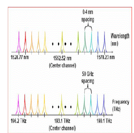
| Dense wavelength division multiplexing (DWDM) refers Originally to optical signals multiplexed within the
1550 nm band so as to leverage the capabilities (and cost) of erbium doped fiber amplifier (EDFAs), which are
effective for wavelengths between approximately 1525–1565 nm (C band), or 1570–1610 nm (L band). Dense
wavelength division multiplexing (DWDM) is a technology which multiplexes a number of optical carrier signals onto
a single optical fiber by using different wavelengths (i.e., colors) of laser light. |
| This technique enables bidirectional communications over one strand of fiber, as well as multiplication of capacity. |
| Dense Wavelength Division Multiplexing (DWDM) is a technology that allows multiple information streams to
be transmitted simultaneously over a single fiber at data rates as high as the fiber plant will allow (e.g. 2.4 Gb/s).
The DWDM approach multiplies the simple 2.4 Gb/s system by up to 16 times, giving an immense and immediate
increase in capacity-using embedded fiber. A sixteen channel system (which is available today) supports 40 Gb/s in
each direction over a fiber pair, while a 40 channel system under
Development will support 100 Gb/s, the equivalent of ten STM–64/OC–192 transmitters. |
| The benefits of DWDM over the first two options-adding fiber plant or deploying STM 64/OC-192 for increasing
capacity are clear. |
| DWDM System components |
| • DWDM terminal multiplexer |
| • Intermediate line repeater |
| • optical add-drop multiplexer |
| • Optical Supervisory Channel (OSC) |
| • DWDM terminal demultiplexer |
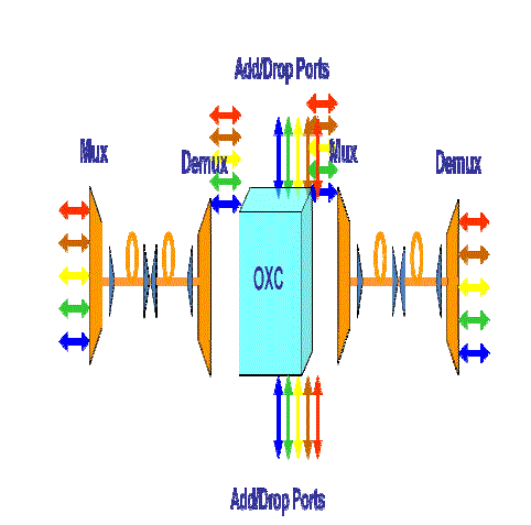
| • The terminal multiplexer multiplexes the all the signals (SONET/SDH, ATM etc) and It will be sent through
optical fiber. |
| An intermediate line repeater is place approximately every 80-100 km to compensate for the loss of optical power
as the signal travels along the fiber. Between multiplexing and demultiplexing points in a DWDM system, there is an
area in which multiple wavelengths exist The OSC carries information about the multi-wavelength optical signal as
well as remote conditions at the optical terminal. The terminal demultiplexer breaks the multi-wavelength signal
back into individual signals and outputs them on separate fibres for client-layer systems (such as SONET/SDH) to
detect |
| C. ROADM |
| It is form of an optical add drop multiplexer.It allows individual or multiple wavelengths carrying data channels
added or dropped from transport fiber without converting signal on all the DWDM channels to electric signal &back
again optical signals. In fiber optics, a reconfigurable optical add-drop multiplexer (ROADM) is a form of optical adddrop
multiplexer that adds the ability to remotely switch traffic from a wavelength-division multiplexing (WDM)
system at the wavelength layer. This is achieved through the use of a wavelength selective switching module. This
allows individual or multiple wavelengths carrying data channels to be added and/or dropped from a
transport fiber without the need to convert the signals on all of the WDM channels to electronic signals and back again
to optical signals. The main advantages of the ROADM are: The planning of entire bandwidth assignment need not be
carried out during initial deployment of a system. The configuration can be done as and when required without
affecting traffic already passing the ROADM.ROADM allows for remote configuration and reconfiguration. In
ROADM, as it is not clear beforehand where a signal can be potentially routed, there is a necessity of power balancing
of these signals. ROADMs allow for automatic power balancing. |
NETWORK PLANNING |
| A . Process Flow |
| The below Flow Chart will give a general overview of the Process Involved during an individual project phase. |
| 1. Gather All information required to start the Project |
| 2. Gather Site Survey and Fiber Characterization results (if any) |
| 3. Create Rack Front View (RFV) using the Stencils and Diagram Templates using Microsoft Visio software |
| 4. Create Signal Flow Diagrams (SFD) Using the Stencils and Diagram Templates using Microsoft Visio. |
| 5. Gather IP and Commissioning related information Form the customer to complete |
| 6. .Commissioning and Provisioning information spreadsheet needs to be created. |
| 7. Get the DND reviewed by a Senior Engineer before Releasing the project files. This completes network
planning completely. |
| .B. Gathering input files |
| Equipment list (Sales Copy/ Bill of Materials BOM) |
| Every Project is identified by a six digit Project Number. The equipment list will consists of all the hardware required
for each site being added in a Network. |
| 1. Each Equipment list will consist to many sections |
| 2. Type and configuration added at each site. |
| 3. Auxiliary shelf equipment – Like Mounting Brackets, Power Harness, Cooling Unit, etc. |
| 4. Common Equipment- Consists of Filler Cards, Access Panel, Shelf Processors, Power Interface |
| 5. Broadband Interfaces and photonic interface |
| 6. Project related equipments-fibre management, ac rectifier |
| Photonic Configuration |
| Whenever the configuration of the Network being deployed is a Photonic Configuration, we require what is called
the Modeler or the OPNET. The OPNET report gives details about the network connectivity, what Amplifiers is facing
which direction, the wavelengths to be assigned, where attenuator pads should be used and the values to be used. All
the photonic components will be a part of this input file
The excel file and either of the Visio or the PDF File should be available to start the DND Process for a Network with
Photonic/DWDM Configuration. |
| C. DETAILED NETWORK DESIGN: |
| The various parts involved in Detailed Network Design are as below: |
| Rack Front View |
| Rack Front View is also referred as RFV. Rack Front View is a Visio file document which would indicate the
installers the shelf and cards positions when they are on site installing the equipment. This file consists of a Rack Front
view along with different components going into different slots. For all site |
| Signal Flow Diagram |
| Signal Flow Diagram is also referred as SFD. Signal Flow Diagram is an indication for the various inters
connections that need to be done in a Site where the 6500 shelf is being added |
| Commissioning and Provisioning |
| Commissioning and Provisioning is an excel Spreadsheet document that is provided to the Field Engineering team to
perform Commissioning and provisioning of the 6500 shelf at each site based on the configuration and the inputs
received from the Customer. Each Type of Configuration that is configurable on a 6500 shelf is has different
provisioning parameters. These parameters are to be taken into consideration for a particular type of configuration and
the fields in the Provisioning tab of the spreadsheet. |
| Project Network Diagram |
| Project Network diagram also referred as PND is another Visio document which would give an overall view of the
Network topology. PND is only done where ever applicable and necessary. |
RESULT |
| Network planning includes detailed network design (DND). As per the detailed network design procedure, for all sites
Rack front view (RFV) created, Signal flow diagram (SFD) created for all sites. Similarly project network diagram
(PND) developed which gives over all network topology and C&P has been developed. This completes the detailed
network design (DND).Microsoft Visio software used to do network planning. |
| After designing the DND file or Document has to be sent to site /field engineers. They will configure as per the detailed
network document and install. After completion of Installation finally network will be tested for 12hours or
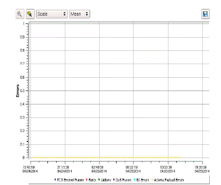
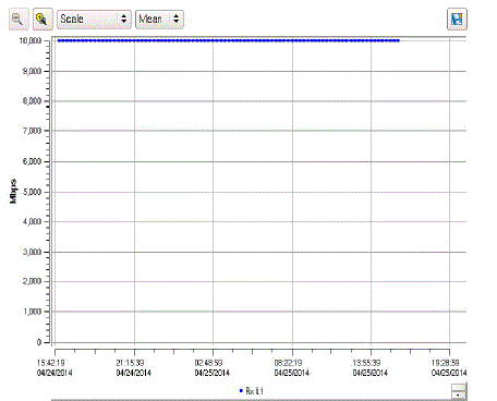
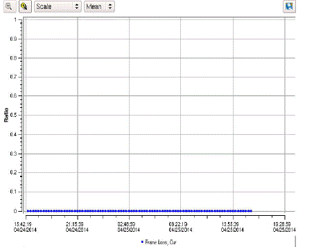
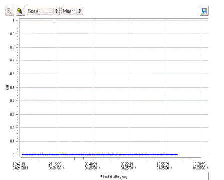
24hours.our network has been tested for 24 hours. The result of the tested network has shown in below |
| After network testing (Bit error rate testing) there is no Frame loss or packet jitter found in the network, from this we
can conclude that network is error free. |
CONCLUSION |
| In our project Network planning and engineering has been completed which includes detailed network design. After
designing of the network, It has been tested for 24hours. Network test(Bit error testing) shown that our Network is
completely error free. Finally we concluded that, after network planning/design and engineering for fiber optic
transport system using DWDM system, the designed network is completely efficient. |
Figures at a glance |
 |
 |
 |
| Figure 1 |
Figure 2 |
Figure 3 |
 |
 |
 |
| Figure 4 |
Figure 5 |
Figure 6 |
|
| |
References |
- Reena Antil, Pinki, Mrs. Sonal Beniwal, ”An Overview of DWDM Technology & Network” International journal of Scientific & Technology
Research Volume 1,Issue 11,Dec 2012
- Wu CHEN, ” A Novel Optimization Method of Optical Network Planning” The engineering & technical college of Chengdu university of
technology, leshan, 614000,china,
- I. P. Kaminow, et al, “A Wideband All-Optical WDM Network”, IEEE Journal on Selected Areas in Communications, Vol.14, No. 5, June
1996, pp. 780 - 799
- Melián, B., Laguna, M., and Moreno, J.A., "Capacity expansion of fiber optic networks with WDM systems: Problem formulation and
comparative analysis", Computers and Operations Research, 31(3) (2004) 461- 472
- B. Mukherjee, “WDM-based local lightwave networks—Part I:Single-hop systems,” IEEE Network Mag., vol. 6, pp. 12–27, May .1992
- R. Ramaswami and K. Sivarajan, “Optical Networks “(Morgan, San Francisco, 2009). works, IEEE TRANSACTIONS ON COMPUTERS,
VOL. 62, NO. 9, SEPTEMBER 2013 by Octav Chipara , Chenyang Lu , Senior Member, IEEE Computer Society, and Gruia-Catalin Roman,
Member, IEEE Computer Society.
- S. Melle, C. P. Pfistner, and F. Diner, “Amplifier and multiplexing technologies expand network capacity,” Lightwave Mag., pp. 42–46,
- , “Optical Fiber Communication: From Transmission to Networking“ IEEE Transactions on Communications, 40(5):138–147, May Dec.1995
- K. Bala, S. Giebl, R. Ramamurthy, W. Russ, and B. Tang, “IP centric control and signaling for optical lightpaths,” in Optical Internetworking
Forum, Jan. 2000, OIF2000.019.
- R. Ramaswami2002Special Issue on High-Capacity Optical Transport Networks, IEEE J. Select. Areas Commun., vol. 16, Sept. 1998.
|