Keywords
|
| Feed forward neural network, Image denoising, Impulse noise, Nonlinear filter. |
INTRODUCTION
|
| The standard median filter is a simple rank selection filter and attempts to remove impulse noise from the center pixel of the processing window by changing the luminance value of the center pixel with the median of the luminance values of the pixels contained within the window. This approach provides a reasonable noise removal performance with the cost of introducing undesirable blurring effects into image details even at low noise densities. Since its application to impulse noise removal, the median filter has been of research interest and a number of rank order based filters trying to avoid the inherent drawbacks of the standard median filter have been investigated [1-7]. These filters yield better edges and fine detail preservation performance than the median filter at the expense of reduced noise suppression. |
| Conventional order statistics filters usually distort the uncorrupted regions of the input image during restoration of the corrupted regions, introducing undesirable blurring effects into the image. In switching median filters, the noise detector aims to determine whether the center pixel of a given filtering window is corrupted or not. If the center pixel is identified by the noise detector as corrupted, then the output of the system is switched to the output of the noise filter, which has the restored value for the corrupted pixel. if the center pixel is identified as uncorrupted, which means that there is no need to perform filtering, the noise removal operator is bypassed and the output of the system is switched directly to the input. This approach has been employed to significantly exploiting different impulse detection mechanisms have been investigated [8-28]. Existing switching median filters are commonly found to be non-adaptive to noise density variations and prone to misclassifying pixel characteristics. This exposes the critical need to evolve a sophisticated switching scheme and median filter. In order to improve filtering performances, decision-based median filtering schemes had been investigated. These techniques aim to achieve optimal performance over the entire image. The existing filters either suppress the noise at the cost of reduced noise suppression performance. In order to address these issues, many neural networks have been investigated for image denoising [29-39]. In the last few years, there has been a growing interest in the applications of digital signal processing. Neural networks are low-level computational structures that perform well when dealing raw data although neural networks can learn. |
| In addition to these, the back-propagation learning algorithm is simple to implement and computationally efficient in which its complexity is linear in the synaptic weights of the neural network. The input-output relation of a feed forward adaptive neural network can be viewed as a powerful nonlinear mapping. Conceptually, a feed forward adaptive network is actually a static mapping between its input and output spaces. Even though, intelligent techniques required certain pattern of data to learn the input. This filtered image data pattern is given through nonlinear filter for training of the input. Therefore, intelligent filter performance depends on conventional filters performance. This work aims to achieving good de-noising without compromising on the useful information of the signal. |
| In this paper, a novel structure is proposed to eliminate the impulse noise and preserves the edges and fine details of digital images. A feed forward neural architecture with back propagation learning algorithm is used and is referred as an Neural Filtering Technique for digital image enhancement. The proposed intelligent filtering operation is carried out in two stages. In first stage the corrupted image is filtered by applying a special class of filtering technique. This filtered image output is suitably combined with a feed forward neural (FFN) network in the second stage. The internal parameters of the feed forward neural network are adaptively optimized by training of the feed forward back propagation algorithm. |
| The rest of the paper is organized as follows. Section 2 describes the noise model. Section 3 explains the structure of the proposed filter and its building blocks. Section 4 discusses the results of the proposed filter on different test images. 5 is the final section, presents the conclusion. |
NOISE MODEL
|
| Fundamentally, there are three standard noise models, which model the types of noise encountered in most images; they are additive noise, multiplicative noise and impulse noise. Digital image are often corrupted by salt and pepper noise (or impulse noise). Impulse noise is considered for the proposed work. For images corrupted by salt-and-pepper noise (respectively fixed-valued noise), the noisy pixels can take only the maximum and the minimum values (respectively any random value) in the dynamic range. in other words, an image containing salt-and-pepper noise will have dark pixels in bright region and bright pixels in dark regions. A digital image function is given by f(i,j) where (i,j) is spatial coordinate and f is intensity at point(i,j). Let f(i,j) be the original image, g(i,j) be the noise image version and η be the noise function, which returns random values coming from an arbitrary distribution. Then the additive noise is given by the equation (1) |
 |
| Impulse noise is caused by malfunctioning pixels in camera sensors, dead pixels, faulty memory locations in hardware, erroneous transmission in a channel, analog to digital converter, malfunctioning CCD elements (i.e. hot and dead pixels) and flecks of dust inside the camera most commonly cause the considered kind of noise etc. It also creeps into the images because of bit errors in transmission, faulty memory locations and erroneous switching during quick transients. Two common types of impulse noise are the salt and pepper noise and the random valued noise. The proposed filter first detects the salt and pepper noise present in digital images in very efficient manner and then removes it. As the impulse noise is additive in nature, noise present in a region does not depend upon the intensities of pixels in that region. Image corrupted with impulse noise contain pixels affected by some probability. The intensity of greyscale pixel is stored as an 8-bit integer giving 256 possible different shades of gray going from black to white, which can be represented as a [0,L-1] [L is 255] integer interval. in this paper the impulse noise is considered. In case of images corrupted by this kind of salt and pepper noise, intensity of the pixel Aij at location (i,j) is described by the probability density function given by the following equation (2) |
 |
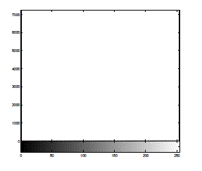
| where a is the minimum intensity (dark dot); b is the maximum intensity (light dot); pa is the probability of intensity "a" generation; pb is the probability of intensity "b" generation; p is the noise density, and Yij of the pixel at location (i,j) in the uncorrupted image. If either pa or pb is zero, the impulse noise is called unipolar noise. If neither probability is zero and especially if they are equal, impulse noise is called bipolar noise or salt-and-pepper noise. Figure 1 shows the histogram of salt & pepper noise pattern with equal probabilities and impulse noise pattern is illustrated in Fig.1. |
PROPOSED FILTER
|
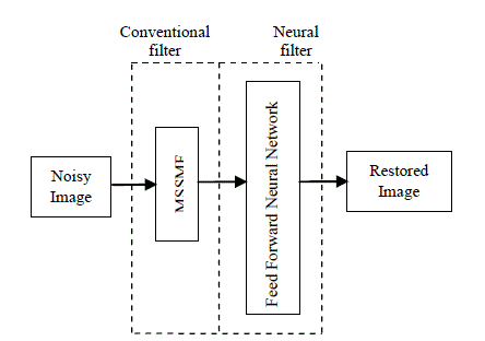
| A feed forward neural network is a flexible system trained by heuristic learning techniques derived from neural networks can be viewed as a 4-layer neural network with weights and activation functions. Fig.2 shows the structure of the proposed impulse noise removal filter. The proposed filter is obtained by appropriately combining output image from new tristate switching median filter with neural network. Learning and understanding aptitude of neural network congregate information from the two filters to compute output of the system which is equal to the restored value of noisy input pixel. |
| The neural network learning procedure is used for the input-output mapping which is based on learning the proposed filter and the neural network utilizes back propagation algorithm. The special class of filter is described in section 3.1. |
3.1 Multistate Switching median filter [27]
|
| Switching is nothing but thresholding and only fixed threshold is selected for all the pixels in an image. Although at lower level of noise, the thresholding performance is satisfactorily restore the digital images. It is found to exhibit inadequate performance in the case of images corrupted at medium level and higher level of impulse noise. The main advantages of that tri-state median filter is integrates the two filters into a new one and it take advantages of that two filters, so it will reduce the degradation properties of impulse noise more efficiently. Therefore the proposed filtering technique is obtained by suitably combining decision based median filter [25] and switching median filter [26]. The proposed filtering operation is explained in the following section 3.1. |
| A proposed filter is obtained by duly combing output images from switching median filter and decision based median filter. Here, there are two types of comparison can be carry out to improve the noise reduction. First one is based on switching median filter and second one is based on decision based median filter. In order to enhance the digital images, switching median filter is combined with Decision based median filter to form the proposed multistate switching median filter. This switching median filter has better edge preserving properties. Decision based filter has improved performance in retaining both the homogenous region of image as well as edge region of image satisfactorily. Therefore, these two filter outputs are considered and integrated together to form the multistate switching median filter. The proposed filtering algorithm as applied on noisy image is described in steps as follows: |
| Step1) A two-dimensional square filtering window of size 3x3 is slid over the noisy image. |
| Step 2) As the window move over the noisy image, at each point the central pixel inside the window is checked whether it is a corrupted pixel or not. If the pixel is an uncorrupted one, it is left undisturbed and the window is moved to the next position. On the other hand, if the pixel is detected as a corrupted one, the filtering procedure is performed by following the further steps described below. |
| Step 3) Determine the absolute difference between pixels from filtered image and pixels from noisy image (i.e. input image) and is described in the following equation: |
 |
 |
| where, D1 is an absolute difference between original pixel value and switching median filter (SMF), D2 is an absolute difference between original pixel value and decision based median filter (DBF), X(i,j) is the noisy image, YDBF(i,j) is the decision based median filtered (DBF) output, YSMF(i,j) is the switching median filter (SMF) output. |
| Step 4) Check if threshold is greater than or equal to image absolute difference D1, then the central pixel is consider as noise free pixel and is left unaltered. Otherwise go to step6. |
| Step 5) If T is greater than or equal to D2 and less than equal to D1, then the processing pixel is replaced by the pixel from switching median filtered output image. |
| Step 6) Again check if T is less than D2, then the processing pixel is replaced by the pixel from decision based filtered output image. |
| Then the window is moved to form a new set of values, with the next pixel to be processed at the centre of the window. This process is repeated until the last image pixel is processed. The multistate switching median filter integrates the advantages of both switching filter and decision based filter. The performance of the proposed filter is superior to other existing filters in terms of eliminating impulse noise and preserving edges and features of images. This filter output is as an input for neural network training. |
3.2 Feed forward Neural Network
|
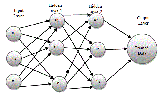
| In feed forward neural network, back propagation algorithm is computationally effective and works well with optimization and adaptive techniques, which makes it very attractive in dynamic nonlinear systems. This network is popular general nonlinear modeling tool because it is very suitable for tuning by optimization and one to one mapping between input and output data. The input-output relationship of the network is as shown in Fig.3. |
| In Fig.3 xm represents the total number of input image pixels as data, nkl represents the number of neurons in the hidden unit, k represents the number hidden layer and l represents the number of neurons in each hidden layer. A feed forward back propagation neural network consists of two layers. The first layer or hidden layer, has a tan sigmoid (tan-sig) activation function is represented by |
 |
| This function is a hyperbolic tangent which ranges from -1 to 1, yi is the output of the ith node (neuron) and vi is the weighted sum of the input and the second layer or output layer, has a linear activation function. Thus, the first layer limits the output to a narrow range, from which the linear layer can produce all values. The output of each layer can be represented by |
 |
| where Y is a vector containing the output from each of the N neurons in each given layer, W is a matrix containing the weights for each of the M inputs for all N neurons, X is a vector containing the inputs, b is a vector containing the biases and f(·) is the activation function for both hidden layer and output layer. |
| The trained network was created using the neural network toolbox from Matlab9b.0 release. In a back propagation network, there are two steps during training. The back propagation step calculates the error in the gradient descent and propagates it backwards to each neuron in the hidden layer. In the second step, depending upon the values of activation function from hidden layer, the weights and biases are then recomputed, and the output from the activated neurons is then propagated forward from the hidden layer to the output layer. The network is initialized with random weights and biases, and was then trained using the Levenberq-Marquardt algorithm (LM). The weights and biases are updated according to |
 |
| where Dn is a matrix containing the current weights and biases, Dn+1 is a matrix containing the new weights and biases, e is the network error, J is a Jacobian matrix containing the first derivative of e with respect to the current weights and biases. In the neural network case, it is a K-by-L matrix, where K is the number of entries in our training set and L is the total number of parameters (weights+biases) of our network. It can be created by taking the partial derivatives of each in respect to each weight, and has the form: |
 |
| where F(xi,L) is the network function evaluated for the i-th input vector of the training set using the weight vector L and wj is the j-th element of the weight vector L of the network. In traditional Levenberg-Marquardt implementations, the jacobian is approximated by using finite differences, Howerever, for neural networks, it can be computed very effieciently by using the chain rule of calculus and the first derivatives of the activation functions. For the least-squares problem, the Hessian generally doesn't needs to be caclualted. As stated earlier, it can be approximated by using the Jacobian matrix with the formula: |
 |
| I is the identity matrix and μ is a variable that increases or decreases based on the performance function. The gradient of the error surface, g, is equal to JTe. |
3.3 Training of the Feed Forward Neural Network
|
| Feed forward neural network is trained using back propagation algorithm. There are two types of training or learning modes in back propagation algorithm namely sequential mode and batch mode respectively. In sequential learning, a given input pattern is propagated forward and error is determined and back propagated, and the weights are updated. Whereas, in Batch mode learning; weights are updated only after the entire set of training network has been presented to the network. Thus the weight update is only performed after every epoch. It is advantageous to accumulate the weight correction terms for several patterns. For better understanding, the back propagation learning algorithm can be divided into two phases: propagation and weight update. First phase is a propagation phase; each propagation involves the following steps: Forward propagation of a training pattern's input through the neural network in order to generate the propagation's output activations. |
| a) Backward propagation of the propagation's output activations through the neural network using the training pattern's target in order to generate the deltas of all output and hidden neurons. |
| In second phase, each weight-synapse follow the following steps: |
| a) Multiply its output delta and input activation to get the gradient of the weight. |
| b) Bring the weight in the opposite direction of the gradient by subtracting a ratio of it from the weight. |
| This ratio influences the speed and quality of learning; it is called the learning rate. The sign of the gradient of a weight indicates where the error is increasing; this is why the weight must be updated in the opposite direction. Repeat phase 1 and 2 until the performance of the network is satisfactory. |
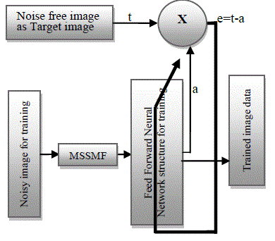
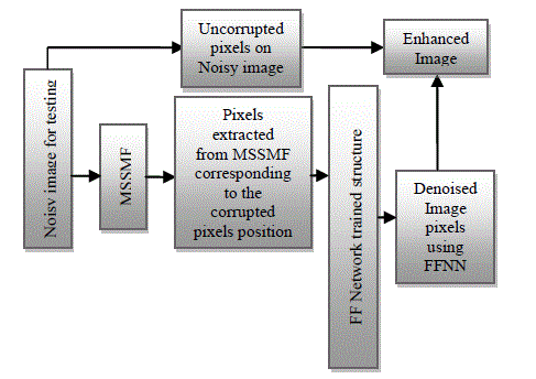
| In addition, neural network recognizes certain pattern of data only and also it entails difficulties to learn logically to identify the error data from the given input image. In order to improve the learning and understanding properties of neural network, filtered output is introduced for training.New switching median filter output data is considered as an input for neural network training and noise free image is considered as a target image for training of the neural network. Back propagation is pertained as network training principle and the parameters of this network are then iteratively tuned. Once the training of the neural network is completed, its internal parameters are fixed and the network is combined with the nonlinear filters outputs to construct the proposed technique, as shown in Fig.4. While training a neural network, network structure is fixed and the unknown images are tested for given fixed network structure respectively. The performance evaluation is obtained through simulation results and shown to be superior performance to other existing filtering techniques in terms of impulse noise elimination and edges and fine detail preservation The feed forward neural network used in the structure of the proposed filter acts like a mixture operator and attempts to construct an enhanced output image by combining the information from the new tristate switching median filter. The rules of mixture are represented by the rules in the rule base of the neural network and the mixture process is implemented by the mechanism of the neural network. The feed forward neural network is trained by using back propagation algorithm and the parameters of the neural network are then iteratively tuned using the Levenberg– Marquardt optimization algorithm, so as to minimize the learning error, e. The neural network trained structure is optimized and the tuned parameters are fixed for testing the unknown images. |
| The internal parameters of the neural network are optimized by training. Fig.4 represents the setup used for training and here, based on definition, the parameters of this network are iteratively optimized so that its output converges to original noise free image and completely removes the noise from its input image. The well known images are trained using this neural network and the network structure is optimized. The unknown images are tested using optimized neural network structure. |
| In order to get effective filtering performance, already existing neural network filters are trained with image data and tested using equal noise density. But in practical situation, information about the noise density of the received signal is unpredictable one. Therefore; in this paper, the neural network architecture is trained using denoised three well known images which are corrupted by adding different noise density levels of 0.4, 0.45, 0.5 and 0.6 and also the network is trained for different hidden layers with different number of neurons. Noise density with 0.45 gave optimum solution for both lower and higher level noise corruption. Therefore images are corrupted with 45% of noise is selected for training. Then the performance error of the given trained data and trained neural network structure are observed for each network. Among these neural network Structures, the trained neural network structure with the minimum error level is selected (10-3) and this trained network structures are fixed for testing the received image signal. |
| Network is trained for 33 different architectures and corresponding network structure is fixed. PSNR is measured on Lena test image for all architectures with various noise densities. Among these, based on the maximum PSNR values; selected architectures is summarized in table 4 for Lena image corrupted with 50% impulse noise. Finally, the maximum PSNR value with the neural network architecture of noise density 0.45 and two hidden layers with 6 neurons for each layer has been selected for training. |
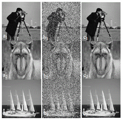
| Fig.5 shows the images which are used for training. Three different images are used for network. This noise density level is well suited for testing the different noise level of unknown images in terms of quantitative and qualitative metrics. The image shown in Fig.5 (a1,2 and3) are the noise free training image: cameraman Baboonlion and ship. The size of an each training image is 256 x 256. The images in Fig.5 (b1,2 and 3) are the noisy training images and is obtained by corrupting the noise free training image by impulse noise of 45% noise density. The image in Fig.5 (c1,2 and 3) are the trained images by neural network. The images in Fig.5 (b) and (a) are employed as the input and the target (desired) images during training, respectively. |
3.4 Testing of unknown images using trained structure of neural network
|
| The optimized architecture that obtained the best performance for training with three images has 196608 data in the input layer, two hidden layers with 9 neurons for each layer and one output layer. The network trained with 45% impulse noise shows superior performance for testing under various noise levels. Also, to ensure faster processing, only the corrupted pixels from test images are identified and processed by the optimized neural network structure. As the uncorrupted pixels do not require further processing, they are directly taken as the output. |
| The chosen network has been extensively tested for several images with different level of impulse noise. Fig.5 shows the exact procedure for taking corrupted data for testing the received image signals for the proposed filter. In order to reduce the computation time in real time implementation; in the first stage, a special class of filter is applied on unknown images and then pixels (data) from the outputs of new tristate switching median filter is obtained and applied as inputs for optimized neural network structure for testing; these pixels are corresponding to the pixel position of the corrupted pixels on noisy image. |
| At the same time, noise free pixels from input are directly taken as output pixels. The tested pixels are replaced in the same location on corrupted image instead of noisy pixels. The most typical feature of the proposed filter offers excellent line, edge, and fine detail preservation performance and also effectively removes impulse noise from the image. Usually conventional filters are giving denoised image output and then these images are enhanced using these conventional outputs as input for neural filter while these outputs are combined with the network. Since, networks need certain pattern to learn and understand the given data. |
3.5 Filtering of the Noisy Image
|
| The noisy input image is processed by sliding the 3x3 filtering window on the image. This filtering window is considered for the nonlinear filter. The window is started from the upper-left corner of the noisy input image, and moved rightwards and progressively downwards in a raster scanning fashion. For each filtering window, the nine pixels contained within the window of noisy image are first fed to the new tristate switching median filter. Next, the center pixel of the filtering window on noisy image, the output of the conventional filtered output is applied to the appropriate input for the neural network. Finally, the restored image is obtained at the output of this network. |
RESULTS AND DISCUSSION
|
| The performance of the proposed filtering technique for image quality enhancement is tested for various level impulse noise densities. Four images are selected for testing with size of 256 x 256 including Baboon, Lena, Pepper and Ship. All test images are 8-bit gray level images. The experimental images used in the simulations are generated by contaminating the original images by impulse noise with different level of noise density. The experiments are especially designed to reveal the performances of the filters for different image properties and noise conditions. The performances of all filters are evaluated by using the peak signal-to-noise ratio (PSNR) criterion, which is defined as more objective image quality measurement and is given by the equation (6) |
 where where |
 |
| Here, M and N represents the number of rows and column of the image and x(i, j) and y(i, j) represents the original and the restored versions of a corrupted test image, respectively. Since all experiments are related with impulse noise. |
| The experimental procedure to evaluate the performance of a proposed filter is as follows: The noise density is varied from 10% to 90% with 10% increments. For each noise density step, the four test images are corrupted by impulse noise with that noise density. This generates four different experimental images, each having the same noise density. These images are restored by using the operator under experiment, and the PSNR values are calculated for the restored output images. By this method ten different PSNR values representing the filtering performance of that operator for different image properties, then this technique is separately repeated for all noise densities from 10% to 90% to obtain the variation of the average PSNR value of the proposed filter as a function of noise density. The entire input data are normalized in to the range of [0 1], whereas the output data is assigned to one for the highest probability and zero for the lowest probability. |
| The architecture with two hidden layers and each hidden layer has 9 neurons yielded the best performance. The various parameters for the neural network training for all the patterns are summarized in Table 2 and 3. In Table 2, Performance error is nothing but Mean square error (MSE). It is a sum of the statistical bias and variance. The neural network performance can be improved by reducing both the statistical bias and the statistical variance. However there is a natural trade-off between the bias and variance. Learning Rate is a control parameter of training algorithms, which controls the step size when weights are iteratively adjusted. The learning rate is a constant in the algorithm of a neural network that affects the speed of learning. It will apply a smaller or larger proportion of the current adjustment to the previous weight If LR is low, network will learn all information from the given input data and it takes long time to learn. If it is high, network will skip some information from the given input data and it will make fast training. However lower learning rate gives better performance than higher learning rate. The learning time of a simple neuralnetwork model is obtained through an analytic computation of the Eigen value spectrum for the Hessian matrix, which describes the second-order properties of the objective function in the space of coupling coefficients. The results are generic for symmetric matrices obtained by summing outer products of random vectors. |
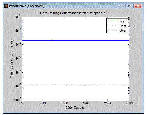
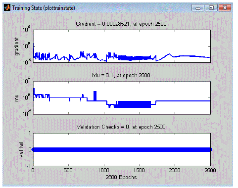
| In Fig.7 and Fig.8 represent Performance error graph for error minimization and training state respectively. This Learning curves produced by networks using non-random (fixed-order) and random submission of training and also this shows the error goal and error achieved by the neural system. |
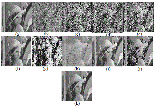
| Fig.9 Subjective Performance comparison of proposed filter with other existing filters on test image Lena (a) Noise free images, (b) image corrupted by 70% impulse noise, (c) images restored by TSMF, (c) images restored by MDBSMF, (e) images restored by NID, (f) images restored by IDBA, (g)images restored by DBF1, (h) images restored by DBF2, (i) images restored by DBF3 and (j) image restored by TSSMF and (k) image restored by proposed filter |
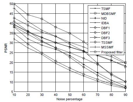
| In order to prove the effectiveness of this filter, existing filtering techniques are experimented and compared with the proposed filter for visual perception and subjective evaluation on Lena image including Tri state median filter (TSMF), Multiple decision based median filter (MDBMF), a New impulse detector (NID), Improved dfecision based algorithm (IDBA), Decision based filter1 (DBF1), Decision based filter2 (DBF2), Decision based filter3 (DBF3), tristate switching median filter (TSSMF), Multistate switching median filter (MSSMF) and proposed filter in Fig.9. Lena test image contaminated with the impulse noise of various densities are summarized in Table3 for quantitative metrics for different filtering techniques and compared with the proposed filtering technique and is graphically illustrated in Fig.10. |
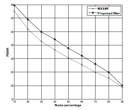
| The summarized values for decision based switching median filter; nonlinear filter and the proposed filter are graphically illustrated in Fig.11 for the performance comparison of the proposed intelligent filter. This qualitative measurement proves that the proposed filtering technique outperforms the other filtering schemes for the noise densities up to 50%. |
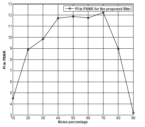
| The PSNR performance explores the quantitative measurement. In order to check the performance of the feed forward neural network, percentage improvement (PI) in PSNR is also calculated for performance comparison between conventional filters and proposed neural filter for Lena image and is summarized in Table 4. This PI in PSNR is calculated by the following equation 8. |
 |
| where PI represents percentage in PSNR, PSNRCF represents PSNR for conventional filter and PSNRNF represents PSNR values for the designed neural filter. Here, the conventional filters are combined with neural network which gives the proposed filter, so that the performance of conventional filter is improved. In Table 4, the summarized PSNR values for conventional filters namely NF and DBSMF seem to perform well for human visual perception when images are corrupted up to 30% of impulse noise. These filters performance are better for quantitative measures when images are corrupted up to 50% of impulse noise. In addition to these, image enhancement is nothing but improving the visual quality of digital images for some application. In order to improve the performance of visual quality of image using these filters, image enhancement as well as reduction in misclassification of pixels on a given image is obtained by applying Feed forward neural network with back propagation algorithm. |
| The summarized PSNR values in Table 4 for the proposed neural filter appears to perform well for human visual perception when images are corrupted up to 50% of impulse noise. These filters performance are better for quantitative measures when images are corrupted up to 70% of impulse noise. PI is graphically illustrated in Fig.12. |
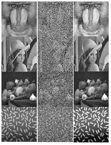
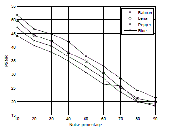
| Digital images are nonstationary process; therefore depends on properties of edges and homogenous region of the test images, each digital images having different quantitative measures. Fig.13 illustrate the subjective performance for proposed filtering Technique for Baboon, Lena, Pepper and Rice images: noise free image in first column, images corrupted with 70% impulse noise in second column, Images restored by proposed Filtering Technique in third column. This will felt out the properties of digital images. Performance of quantitative analysis is evaluated and is summarized in Table.5. This is graphically illustrated in Fig.14. This qualitative and quantitative measurement shows that the proposed filtering technique outperforms the other filtering schemes for the noise densities up to 70%. Since there is an improvement in PSNR values of all images up to 70% while compare to PSNR values of conventional filters output which are selected for inputs of the network training. The qualitative and quantitative performance of Pepper and Rice images are better than the other images for the noise levels ranging from 10% to 70%. But for higher noise levels, the Pepper image is better. The Baboon image seems to perform poorly for higher noise levels. Based on the intensity level or brightness level of the image, it is concluded that the performance of the images like pepper, Lena, Baboon and Rice will change. Since digital images are nonstationary process. |
| The proposed filtering technique is found to have eliminated the impulse noise completely while preserving the image features quite satisfactorily. This novel filter can be used as a powerful tool for efficient removal of impulse noise from digital images without distorting the useful information in the image and gives more pleasant for visual perception. |
| In addition, it can be observed that the proposed filter for image enhancement is better in preserving the edges and fine details than the other existing filtering algorithm. It is constructed by appropriately combining a two nonlinear filters and a neural network. This technique is simple in implementation and in training; the proposed operator may be used for efficiently filtering any image corrupted by impulse noise of virtually any noise density. |
CONCLUSION
|
| A neural filtering technique is described in this paper. This filter is seen to be quite effective in preserving image boundary and fine details of digital images while eliminating impulse noise. The efficiency of the proposed filter is illustrated applying the filter on various test images contaminated different levels of noise. This filter outperforms the existing median based filter in terms of objective and subjective measures. The corrupted pixels from input image alone are taken for testing the unknown digital images. As a result, misclassification of pixels is avoided. So that the proposed filter output images are found to be pleasant for visual perception. |
Tables at a glance
|
 |
 |
 |
 |
 |
| Table 1 |
Table 2 |
Table 3 |
Table 4 |
Table 5 |
|
Figures at a glance
|
 |
 |
 |
 |
 |
| Figure 1 |
Figure 2 |
Figure 3 |
Figure 4 |
Figure 5 |
 |
 |
 |
 |
 |
| Figure 6 |
Figure 7 |
Figure 8 |
Figure 9 |
Figure 10 |
 |
 |
 |
 |
| Figure 11 |
Figure 12 |
Figure 13 |
Figure 14 |
|
| |
References
|
- J.Astola and P.Kuosmanen Fundamental of Nonlinear Digital Filtering. NewYork:CRC, 1997.
- I.Pitasand .N.Venetsanooulos, Nonlinear Digital Filters:Principles Applications. Boston, MA: Kluwer, 1990.
- W.K. Pratt, Digital Image Processing, Wiley, 1978.
- T.Chen, K.-K.Ma,andL.-H.Chen, “Tristate median filter for image denoising”, IEEE Trans.Image Process., 1991, 8, (12), pp.1834-1838.
- ZhigangZeng and Jun Wang, “Advances in Neural Network Research and Applications”, Lecture notesm springer, 2010.
- M. Barni, V. Cappellini, and A. Mecocci, “Fast vector median filter based on Euclidian norm approximation”, IEEE Signal Process. Lett.,vol.1, no. 6, pp. 92– 94, Jun. 1994.
- Sebastian hoyos and Yinbo Li, “Weighted Median Filters Admitting Complex -Valued Weights and their Optimization”, IEEE transactionson Signal Processing, Oct. 2004, 52, (10), pp. 2776-2787.
- E.Abreu, M.Lightstone, S.K.Mitra, and K. Arakawa, “A new efficient approach for the removal of impulse noise from highly corruptedimages”,IEEE Trans. Image Processing, 1996, 5, (6), pp. 1012–1025.
- T.Sun and Y.Neuvo, “Detail preserving median filters in image processing”, Pattern Recognition Lett., April 1994, 15, (4), pp.341-347.
- Zhang and M.- A. Karim, “A new impulse detector for switching median filters”, IEEE Signal Process. Lett., Nov. 2002, 9, (11), pp.360–363.
- 1 Z. Wang and D. Zhang, “Progressive Switching median filter for the removal of impulse noise from highly corrupted images”, IEEE Trans.Circuits Syst. II, Jan. 2002, 46, (1), pp.78–80.
- H.-L. Eng and K.-K. Ma, “Noise adaptive soft –switching median filter,” IEEE Trans.Image Processing, , Feb. 2001, 10, (2), pp. 242–25.
- Pei-Eng Ng and Kai - Kuang Ma, “A Switching median filter with boundary Discriminative noise detection for extremely corrupted images”,IEEE Transactions on image Processing, June 2006, 15, (6), pp.1500-1516.
- Tzu – Chao Lin and Pao - Ta Yu, “salt – Pepper Impulse noise detection”, Journal of Information science and engineering, June 2007, 4,pp189-198.
- E.Srinivasan and R.Pushpavalli, “ Multiple Thresholds Switching Median Filtering for Eliminating Impulse Noise in Images”, Internationalconference on Signal Processing, CIT, Aug. 2007.
- R.Pushpavalli and E.Srinivasan, “Multiple Decision Based Switching Median Filtering for Eliminating Impulse Noise with Edge andFine Detail preservation Properties”, International conference on Signal Processing, CIT , Aug. 2007.
- Yan ZhouandQuan-huanTang, “Adaptive Fuzzy Median Filter for Images Corrupted by Impulse Noise”, Congress on image and signalprocessing, 2008, 3, pp. 265 – 269.
- ShakairKaisar and Jubayer AI Mahmud, “ Salt and Pepper Noise Detection and removal by Tolerance based selective Ari thmeticMeanFiltering Technique for image restoration”, IJCSNS, June 2008, 8,(6), pp. 309 – 313.
- T.C.Lin and P.T.Yu, “Adaptive two-pass median filter based on support vector machine for image restoration ”, Neural Computation, 2004,16, pp.333-354,
- MadhuS.Nair, K.Revathy, RaoTatavarti, "An Improved Decision Based Algorithm For Impulse Noise Removal", Proceedings ofInternational Congress on Image and Signal Processing - CISP 2008, IEEE Computer Society Press, Sanya, Hainan, China, May 2008, 1,pp.426-431.
- V.Jayaraj and D.Ebenezer,“A New Adaptive Decision Based Robust Statistics Estimation Filter for High Density Impulse Noise in Imagesand Videos”, International conference on Control, Automation, Communication and Energy conversion, June 2009, pp 1 - 6.
- FeiDuan and Yu – Jin Zhang,“A Highly Effective Impulse Noise Detection Algorithm for Switching Median Filters”, IEEE Signalprocessing Letters, July 2010, 17,(7), pp. 647 – 650.
- R.Pushpavalli and G.Sivaradje, “Nonlinear Filtering Technique for Preserving Edges and Fine Details on Digital Image”, InternationalJournal of Electronics and Communication Engineering and Technology, January 2012, 3, (1),pp29-40.
- R.Pushpavalli and E.Srinivasan, “Decision based Switching Median Filtering Technique for Image Denoising”, CiiT International journal ofDigital Image Processing, Oct.2010, 2, (10), pp.405-410.
- R.Pushpavalli, E. Srinivasan and S.Himavathi, “A New Nonlinear Filtering technique”, 2010 International Conference on Advances in RecentTechnologies in Communication and Computing, ACEEE, Oct. 2010, pp1-4.
- R.Pushpavalli and G.Sivaradje, “New Tristate Switching Median Filter for Image Enhancement” International Journal of Advancedresearchabnd Engineering Technology, January-June 2012, 3, (1), pp.55-65.
- 2 R.Pushpavalli and G.Sivaradje, “Multistate Switching Median Filter for Image Enhancement” ICTE Sponsored National Conference onInternet and Web Service Computing (NCIWSC) – 2012, Pondicherry Engineering College, Puducherry, 2 -3 August 2012.
- A.Fabijanska and D.Sankowski, “ Noise adaptive switching median-based filter for impulse noise removal from extremely corruptedimages”, IET image processing, July 2010, 5, (5), pp.472-480.
- S.Esakkirajan, T,Veerakumar, Adabala.NSubramanyam, and C.H. Premchand, “Removal of High Density Salt & pepper Noise ThroughModified Decision based Unsymmetric Trimmed Median Filter”, IEEE Signal processing letters, May 2011, 18, (5), pp.287-290.
- A.L.Betker,T.Szturm, Z. oussavi1,“Application of Feed forward Back propagation Neural Network to Center of Mass Estimation for Use in aClinical Environment”, IEEE Proceedings of Engineering in Medicine and Biology Society, April 2004, Vol.3, 2714 – 2717.
- Chen Jindu and Ding Runtao Ding, “A Feed forward neural Network for Image processing”, in IEEE proceedings of ICSP,pp.1477-1480, 1996.
- Wei Qian, Huaidong Li, Maria Kallergi, Dansheng Song and Laurence P. Clarke, “Adaptive Neural Network for Nuclear MedicineImage Restoration”, Journal of VLSI Signal Processing, vol. 18, 297–315, 1998, Kluwer Academic Publishers.
- R.Pushpavalli, G.Shivaradje, E. Srinivasan and S.Himavathi, “ Neural Based Post Processing Filtering Technique For Image QualityEnhancement”, International Journal of Computer Applications, January-2012.
- GaurangPanchal , AmitGanatra, Y P Kosta and DevyaniPanchal, “Forecasting Employee Retention Probability using Back PropagationNeural Network Algorithm”, Second International Conference on Machine Learning and Computing,2010, pp.248-251.
- SudhansukumarMisra, Ganpati panda and Sukadevmehar, “Cheshev Functional link Artificial neural Networks for Denoising of ImageCorrupted by Salt & Pepper Noise”, International journal of rcent Trends in Engineering, may 2009, 1, (1), pp.413-417.
- Weibin Hong, Wei Chen and Rui Zhang, “ The Application of Neural Network in the Technology of Image processing” , Proceddings of theInternational Conference of Engineers and Computer Sciences, 2009, 1.
- 3 A new methos of denoising mixed noise using limited Grayscale Pulsed Coupled Neural Network”, Cross Quad-Regional Radio Science andWireless Technology Conference, 2011, pp.1411-1413.
- ShamikTiwari, Ajay kumar Singh and V.P.Shukla, “Staistical Moments based Noise Classification using Feed Forward back Peopagationneural Network”, International journal of Computer Applications, March 2011, 18, (2), pp.36-40.
- Anurag Sharma, “ Gradient Descent Feed Forward Neural Networks for Forecasting the Trajectories”, International Journal of AdvancedScience and Technology, September 2011, 34, pp.83-88.
|