In today’s world ROBOTICS is a fast growing and interesting field. ROBOT has sufficient intelligence to cover the maximum area of provided space. It has an infrared sensor which are used to sense the obstacles coming in between the path of ROBOT. It will move in a particular direction and avoid the obstacle which is coming in its path.Autonomous Intelligent Robots are robots that can perform desired tasks in unstructured environments without continuous human guidance. The minimum number of gearmotor allows the walking robot to minimize the power consumption while construct a program that can produce coordination of multi-degree of freedom for the movement of the robot. It is found that two gearmotors are sufficient to produce the basic walking robot and one voltage regulators are needed to control the load where it is capable of supplying enough current to drive two gearmotors for each wheel.
Keywords |
| Wheeled ROBOT, Autonomous, Intelligent, Atmel microcontroller,Gear motor |
I. INTRODUCTION |
| Now a day’s Robotics is part of today’s communication & communication is part of advancement of technology, so we
decided to work on ROBOTICS field, and design something which will make human life today’s aspect.There are
different types of mobile robots which can be divided into several categories consists of wheeled robot, crawlingrobot
and legged robot.This project deals with a wheeled autonomous ROBOT.It is the part of Automation; Robot has
sufficient intelligence to cover the maximum area. This robot uses infrared sensor to detect the obstacle in between the
path and then avoid them to completes its objective. The IR transmitter continuously generate an Infrared signal of
38KHz,when an obstacle comes in the path the infrared signal reflected back from the object and is received by the IR
sensor TSOP1738 and then generate a positive high signal with the help of the receiver circuit that is there is an
obstacle in the path. In such a way the robot is able to detect obstacles of provided space and able to avoid obstacles
coming in between the path of ROBOT with the help microcontroller board and complete its journey. |
| The main motto of designing such type of Robot or the technology is that this technology can be used in today’s very
fast transportation to avoid the accident generally happen in congested or the Metro Politian Areas by applying
emergency break. If we use this technology in the car or any vehicle, it will automatically sense the obstacles then it
will take a side to the available free space. An obstacle may be a living things or any object. Autonomous Intelligent
Robots are robots that can perform desired tasks in unstructured environments without continuous human
guidance.Thus by using this technology in vehicles we make the drive safe. |
| Robot mainly consists of two types of designs- |
| 1. Mechanical design |
| 2. Circuit design. |
II. MECHANICAL DESIGN |
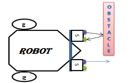
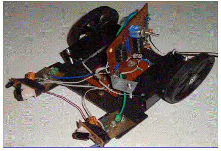
| This includes the hardware design of the robot that is motor &wheel placement, body setup. Robot uses two Robotics
gear motor & wheel for the movement, Which will help it to move forward, left or right. Robot uses two motor &
wheel in the back side and one freewheeling ball is placed at the front which helps it to free movement. The sensor are
placed in such a way that they can cover the maximum area in front of the robot and can be capable to detect an
obstacle either obstacle is small or big. |
III.CIRCUIT DESIGN |
| Circuit design mainly consists of two parts- |
| a)
Sensor part |
| b) Control board part |
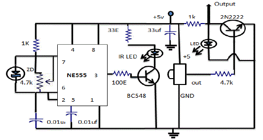
| a) Sensor part:-The sensors used in this robot are Infrared sensor, consisting two part infrared signal generator and the
IR receiver designed in single PCB. There are two sensors are used as left side sensor and right side sensor and two
sensors are used to sense the obstacle on left and right side. |
| IR Generator :-This is a Monostable multivibrator using NE555 IC generating Infrared Signal of 38KHz frequency
for better determination of the object. By using a variable resistance we can adjust the frequency of the IR signal,
detector TSOP1738, gives a high output |
| IR Detector :-IR detector circuit is a circuit which gives a low output in absence of IR signal When some obstacle
come in path IR signal reflected back and fall onto the IR detector. In such a way that obstacle are detected. |
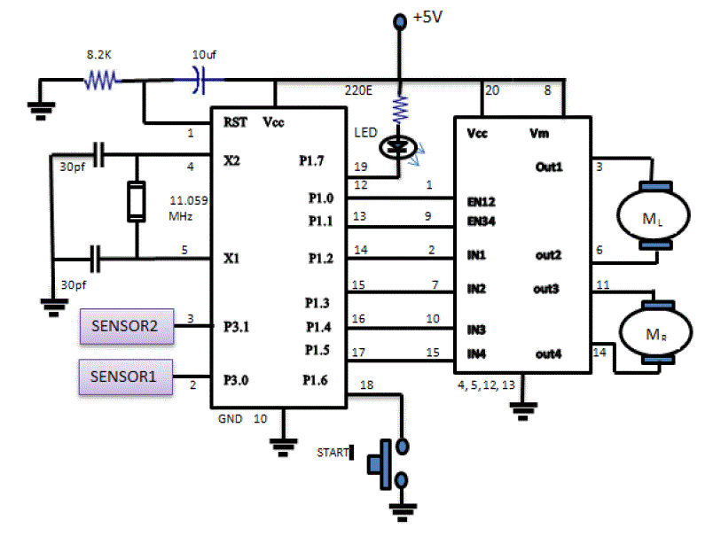
| b) Control board:-
Control board is the main driver circuit of the robot. It mainly contains of the microcontroller of Atmel 89C205I and
the motor driver. |
| The Atmel 89C205Iis a low-voltage, high-performance CMOS 8-bit microcontroller with 2K bytes of Flash
programmable and erasable read-only memory (PEROM). The device is manufactured using Atmel’s high-density nonvolatile
memory technology and is compatible with the industry-standard MCS-51 instruction set. By combining a
versatile 8-bit CPU with Flash on a monolithic chip, the Atmel AT89C2051 is a powerful microcontroller which
provides a highly-flexible and cost-effective solution to many embedded control applications. |
| Motor driver L293D, decide which motor will be in motion or stop in according to the incoming signal from the
microcontrollerAT89C2051. |
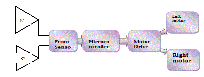
| There are two sensor S1and S2 placed at the left and right side of the Robot to sense the obstacle. These sensors may be
infrared sensors or ultrasonic sensor depending upon the application. |
| Sensors sense the object then generate a signal high or low then signal is processed by the microcontroller
AT80C2051;Microcontroller is programmed to avoid the obstacle, when it get a signal from sensor then by processing
this signal drive the motor driver accordingly ,according to the incoming signal of sensors microcontroller decide
either left or right motor should move. In such a way the Robot works. |
IV. SOFTWARE FRAMWWORK |
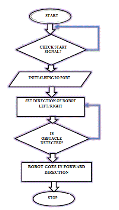
| A brief overview of the software function and the system architecture is shown in Figure 5 to clarify the cyclic phase
rotation for robot movement. From the flowchart, the calling sequence and the relationship between the functions are
visualized. The algorithm and corresponding flowchart has been shown here. |
 |
V. RESULT: WORKING OF ROBOT |
| As the robot is switched ON, 1st it will check either start signal is received or not ,if not then the program counter will
not go to the next address it will remains on the same address until it get a negative signal. Then the robot continuously
check any obstacle in path, if there is no obstacle then robot will go straight. If any obstacle will found in left side then
the controller send a command to the motor drive to stop the right motor & move the left motor and just opposite as
obstacle found in right side. |
VI.APPLICATION |
| Obstacle avoiding technique is very useful in real life, this technique can also use as a vision belt of blind people by
changing the IR sensor by a kinetic sensor ,which is on type of microwave sensor whose sensing range is very high
and the output of this sensor vary in according to the object position changes. This technique makes a blind people able
to navigate the obstacle easily by placing three vibrato in left, right and the centre of a belt named as VISION BELT
and makes a blind people able to walk anywhere.On top of obstacle avoiding robot temperature/pressure sensors can be
added to monitor the atmospheric conditions around. This is useful in places where the environment is not suitable for
humans. |
| Same technology can be used in various application by modifying the microcontroller program for example |
| 1. Line / Path finder Robot . |
| 2. As automatic vacuum cleaner. |
| 3. With proper programming we can use it as a weight lifter. |
| 4. In Mines |
VII.CONCLUSION |
| From this study, a walking robot that achieved the stated objectives had been developed. This robot is able to produce
the basic walking movements using two gearmotors.we developed the robot with a very good intelligence which is
easily capable to sense the obstacle and by processing the signal coming from the sensor it is perfectly avoiding the
obstacle coming in between the path .Robot take the left or right or the forward movement in according to the sensing
signal with the help of the two gear motor which makes the movement of the robot smooth .In future, the sensing range
can be increased by increasing the sensor quality with the help of ultrasonic sensor or the IR signal spread all over the
provide area. |
Figures at a glance |
 |
 |
 |
| Figure 1 |
Figure 2 |
Figure 3 |
 |
 |
 |
| Figure 4 |
Figure 5 |
Figure 6 |
|
| |
References |
- N. Senthil Kumar,M.Saravanan,S Jeebananthan ,“Microprocessors & Microcontrollers”, Oxford University Press,4th Edition,2012,ISBN:978-0- 19-806647-7
- B. Ram, “Fundamental of Microprocessors & Microcontrollers”, Dhanpat Rai Publication,Seventh Edition, ISBN:978-81-89928-60-5
- M. C. Lam, A. S. Prabuwono, H. Arshad, C. S. Chan, “A Real-Time Vision-Based Frameworkfor Human-Robot Interaction”, , 7066Lecture Notes .in Computer Science (Part 1),2011, pp. 257-267, IVIC 2011.
- T. Ishida, and Y. Kuroki, “Sensor System of a small Biped Entertainment Robot”, Advanced Robotics, © VSP and Robotics Society of Japan,Vol. 18, No. 10, pp 1039-1052, 2004,.
- Maikoto T., Koji Y., and Satoshi E., “Studies on Forward Motion of Five Legs Robot”, Journal Code: L0318B 2005, 2P1-S-065, 2005.
- Proceedings of Cooperative Intelligent Robotics in space-II SPIE vol. 1612,Boston, Nov 1991.
- R. A Besari, R. Zamri, A. S. Prabuwono, and S. Kuswadi, “The Study on Optimal Gait for Five-Legged Robot with Reinforcement Learning”, Intelligent .Robotics and Applications, , Vol. 5928, pp. 1170-1175, 2009.
|