In this paper, Particle Swarm Optimization (PSO) based technique for the optimal placement & setting of fuel cell in wind integrated power system is developed. By means of fuel cell optimal placement, it is intended to maximize the system loadability while observing the system stability margins viz., small signal stability, voltage stability, and line stability. The impact of optimal integration using PSO algorithm has been analyzed by studying different system parameters like voltage profile, line flows and real power generation. The objective function to maximize is the load power increase at various buses with respect to the base case load. The active power outputs from the distributed generators are adjusted from their base case power outputs in order to supply the additional load and to minimize the disturbance on the conventional generators due to the fluctuating outputs from wind turbine generators. The application of the scheme is illustrated on Central Travancore Practical Grid System. Newton Raphson power flow method and modal analysis are used to quantify the benefits of the proposed methodology. Results present the maximum system loadability in percentage, optimal location and setting of distributed energy resources, maximum safe bus loading beyond which system becomes unstable.
Keywords |
| Small signal stability, optimal placement, system loadability, distributed energy resources, solid oxide
fuel cell. |
INTRODUCTION |
| Distributed Generators are gaining widespread applications around the world because of the recent technological
advancements in power system towards smart grid technologies. In the current deregulated electricity markets wherein
competition is introduced in generation, transmission and distribution, also strongly favours the integration of
distributed energy resources in order to maximize the utilization of their resources and facilities for maximizing the
profit. Fast depletion of fossil fuels, environmental concerns, advancements in green energy and constraints in erecting
additional transmission and distribution lines are also major reason for development of renewable energy systems as
viable options for future electricity generation. Distributed generations are an effective method to improve system
stability and reliability, reduce transmission losses, increase system loadability, improve system voltage profiles etc. |
| However the integration and high penetration of distributed generations into the power system poses many issues that
need to be addressed carefully. The variations in wind speed and unpredictable solar radiation causes the output powers
from wind and photo voltaic systems to fluctuate considerably. With increased size and complexity of modern power
system, there are chances of cascaded effect of oscillations from a small disturbance leading to complete system black
out. The oscillatory instability is one of the limiting criteria for synchronous operation of distributed generators [1].
Also, the dynamic loadability of a system depends on small signal stability limit [2]. There are other issues like the
optimal allocation of distributed generators to extract maximum technical benefits, like higher stability and security
margins of operations, better voltage profile, increased loadability, reduced losses. |
| In this paper, Particle Swarm Optimization (PSO) based technique for the optimal allocation & setting of Solid Oxide
Fuel Cell (SOFC) in a wind PV integrated power system is developed. By means of SOFC optimal placement, it is
intended to maximize the system loadability while observing the system security and stability margins i.e., small signal
stability, voltage stability, and line stability. The objective function to maximize represents the load power increase
with respect to the base-case load; equality constraints are the power flow equations; and inequality constraints
represents technical limits, such as bus voltage magnitude limits and current flow limits through the branches of the
network. In addition, the active power outputs from the distributed generators are also increased/decreased from their
base case power outputs in order to supply the additional load and minimize the disturbance on the conventional
generators due to the fluctuating outputs from wind turbine generators. |
| The paper is organized as follows, the first section briefs about distributed generators and optimal DG placement
problem. The optimization problem and constraints are formulated in Section 2. Results are detailed in Section 3.
Section 4 summarizes the conclusions and major contributions. |
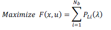
PROBLEM FORMULATION |
| A. Maximize The System Loadability Within Stability Margin |
| The optimization problem to find the optimal location of Fuel Cell DG is formulated as a single objective optimization
problem considering the loadability of all buses as given below |
 |
| Subject to the equality constraint |
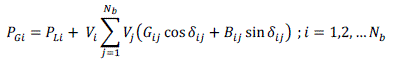 |
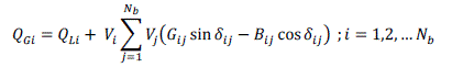 |
| where, PLIis the total active load at bus i and Nb is the total number of buses in the system. |
| The inequality constraints h(x, u)are |
| Apparent power flow limit: |
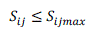 |
| Bus voltage limit: |
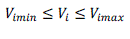 |
| Slack generator power output limit |
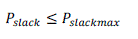 |
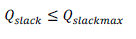 |
| Wind Power output limit. |
| The wind power dispatch should not exceed the available wind power from the wind park: |
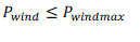 |
 |
| In eq. (1),λ is a load parameter of the system, which maximizes the total power that the network can supply within the
system stability margin. |
| The load factor λ represents the variation of system real & reactive loadsPLI and QLI, defined as: |
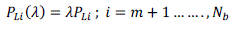 |
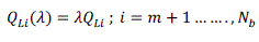 |
| where,m is the total number of generator buses, λ = 1 indicates the base load case. |
| B. Dependent And Control Variables |
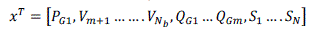
| In eq. (1), x represents the dependent variables. The dependent variables in this analysis are slack bus power PG1, load
bus voltageVm+1…….Nb , generator reactive power outputs QG and apparent power flow SK; x can be expressed as: |
 |
| u represents the control variables. The control variables considered here are generator real power outputs PG except at
the slack bus PG1, generator voltages VG , and the locations of DER device,L: |
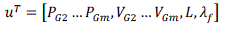 |
| C. Power System Stability Constraints |
| 1) Fast Voltage Stability Index: The safe bus loading of the system is assured by incorporating the Fast Voltage
Stability Index (FVSI) proposed by I. Musirin and A. Rahman [8]. |
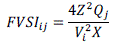 |
| If FVSI≈1.00: bus connected to the line is approaching its instability point. If FVSI≥1.00: one of the buses connected to
the line will experience a sudden voltage drop and the bus will collapse due to overloading. |
| 2) Line Stability Index: The line stability index symbolized by Lmn proposed by M. Moghavemmi and F.M.
Omar [9] is formulated based on a power transmission concept in a single line. The line stability index Lmn is given by |
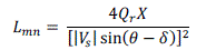 |
| where X is the line reactance, Qr is the reactive power at the receiving end, Vs is the sending end voltage, θ is the line
impedance angle, and δ is the angle difference between the supply voltage and the receiving voltage. The value of
Lmnmust be less than 1.00 to maintain a stable system. |
| 3) Line Stability Factor: System Stability is also assured by Line Stability Factor (LQP) proposed by I. Musirin
and A. Rahman [8]. The LQP should be less than 1.00 to maintain a stable system. |
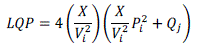 |
| LQP assure that at no level of bus loading the line is overloaded. |
SIMULATION RESULTS & DISCUSSION |
| A. System Description |
| The proposed solution method was tested on Central Travancore Grid (Kerala,India) shown in fig.1. The Central
Travancore grid extends over four districts inKerala, viz. Alleppey, Kottayam, Idukki and Pathanamthitta.The model
consists of 16 buses, and generating stationsat Idukki and Sabarigiri Hydro Power Plants, KayamkulamThermal Power
Plant, Brahmapuram Diesel Power Plant andRamakkelmedu wind farm. The Pallom substation consists ofa 40 MVAR
compensator. The highest voltage level in the testsystem is 220 kV at the transmission side which is steppeddown to
110 kV in the substation. |
| Fuel Cell DG and Solar PV have been connected to different bus and loads are modeled as static loads (constant PQ)
withconstant power factor, and increased according to equations (10) and(11). ThekV rating of DG is the kV of the bus
to whichit is connected. All the lines of the system except line withgenerators are selected to be the optimal location of
theDER.Hence inCentral Travancore System, the locations suitable for fuel cellplacement considered are bus no.s 1, 2,
3, 4, 5, 8, 10, 11, 12,13 and 16. Wind farm consisting of 300 wind turbines and 600 MVA / 220 kV capacity has been
connected to Pallom bus as identified using wind farm placement index [5]. The analysis was done using
PSAT/MATLAB integrated environment as suggested by F. Milano [10]. |
| B. Results & Analysis |
| The DG is placed at arbitrary positions and the resultant power flow results are analyzed. The loadability on the buses
is increased gradually in such a way that the base case power factor is maintained at all loading points. The bus to which Solid Oxide Fuel Cell (SOFC) is connected is modelled as a vθbus and all the additional load is supplied by the
SOFC resulting in minimum load disturbance on the conventional generators. |
| Using particle swarm optimization algorithm, the optimal location of SOFC for maximum loadability was found to be
at bus 1 (Ayarkunnam Bus). The loading of the test system without integrationof SOFC can only be increased to 1.4
times the base caseloading beyond which the system drives into instability and collapses. With the optimal placement
and setting of DG the loadability can be increased from the base case loading of 2.63 p.u to 5.03p.u. Total generation
and load at maximum system loading is given in Table. I. |
| From the table it is obvious that with optimal placement & setting of Distributed Generators (DG), more load demand
can be met. In the present work 2.4p.u additional active load could be handled without driving the system into
instability i.e. an increase of91.2% loading. Voltage profile of power system with fuel cell at bus 1 and without DG is compared in fig. 2. It can be seen that at
maximum system loading the voltages are maintained within the stipulated limits of 0.9 and 1.1 p.u. |
| Fig. 3 shows the Generations at different buses. It can be seen that with optimal placement and setting of fuel cell at bus
1, the conventional generations can be reduced and the whole load disturbance is absorbed by the fuel cell. Bus 2 has
the largest load share. |
| Fig. 4 shows the maximum loadability at different buses with & without DG. |
| In fig. 5 line power flows with and without DG is shown. The line active power flow increases as the system loading is
increased but the stability constraints assures that the increase is within the stability and security margins of the power
system. |
| The stability constraints at the best compromise solution represented by FVSI, LSI and LQP are shown in fig. 6 & fig.7.
It can be seen that voltage and line stability indices (FVSI & LQP) are well within acceptable limits. This maintains
grid stability at various loading ensuring no bus collapses due to overloading and no line is overloaded under any grid
condition. |
STABILITY INDICES |
CONCLUSION |
| In this paper, a new methodology of optimal allocation of distributed energy resources has been proposed to maximize
the system loadability by taking into consideration the power system stability and security constraints. It is found that
PSO based optimization technique is much better to enable optimal allocation of DG in power distribution system.
Incorporation of Fast voltage stability index (FVSI) and Line stability factor (LQP) constraints in the optimization
problem ensures grid stability at various levels of system loadability. With optimal placement of DG near to load center
the most of the load disturbance can be made to be shared by the DG. The applicability of the proposed scheme was
tested on a Central Travancore practical grid system using Newton Raphson power flow method. |
Tables at a glance |
 |
| Table 1 |
|
Figures at a glance |
 |
 |
 |
 |
| Figure 1 |
Figure 2 |
Figure 3 |
Figure 4 |
 |
 |
 |
| Figure 5 |
Figure 6 |
Figure 7 |
|
References |
- D. Lee, L. Wang, (March2008), “Small-Signal Stability Analysis of an Autonomous Hybrid Renewable Energy Power Generation / Energy Storage System Part I: Time-Domain Simulations,”IEEE Trans Energy Convers 2008; 23(1):311–20.
- S. Dahal, N. Mithulananthan, (July 2012), “Assessment and Enhancement of Small Signal Stability of a Renewable-Energy-Based,” no. IEEE Transactions on Sustainable Energy, Vol. 3, No. 3, pp. 407-415.
- I. M. Wartana, J. G. Singh, and W. Ongsakul (July 2011), “Optimal Placement of UPFC for Maximizing System Loadability and Minimize Active Power Losses by NSGA-II,”International Conference on Electrical Engineering and Informatics (ICEEI),pp. 1-6.
- Takur D and Mithulanthan N., (2009). “Influence of constant speed wind turbine generator on power system oscillation.” Electric Power Components and Systems, Vol. 37, pp. 478- 494.
- S. Sreedharan, WeerakornOngasakul, and J. G. Singh (July 2011), “Development of PSO Based Control Algorithms for Maximizing Wind Energy Penetration,” IEEE Power and Energy Society General Meeting,pp. 1-6.
- L. Wang and D. Lee (March 2010), “Load-Tracking Performance of an Autonomous Storage System,”IEEE Transactions On Energy Conversion, Vol. 25, No. 1, pp. 128-139.
- B. Tamimi, C. Caizares, K. Bhattacharya, (July 2011), “Modeling and Performance Analysis of Large Solar Photo-Voltaic Generation on Voltage Stability and Inter-area Oscillations,” IEEE PES General Meeting, pp. 1-6.
- I. Musirin and A. Rahman (November2002), “Estimating Maximum Loadability for Weak Bus Identification Using FVSI,”IEEE Power Engineering Review, vol. 50, pp. 50-52.
- M. Moghavemmi and F.M. Omar (Nov. 1998), “Technique for contingency monitoring and voltage collapse prediction,” IEE Proc. Generation, Transmission and Distribution, vol. 145, pp. 634-640.
- F. Milano (Aug. 2005), “An Open Source Power System Analysis Toolbox,”IEEE Transactions on Power Systems, pp. 1199-1206.
|