Research & Reviews: Journal of Material Sciences
ISSN:2321-6212
ISSN:2321-6212
L.D. Landau Institute for Theoretical Physics, Russia
Received date: 07/08/2018; Accepted date: 14/09/2018; Published date: 21/09/2018
DOI: 10.4172/2321-6212.1000230
Visit for more related articles at Research & Reviews: Journal of Material Sciences
It is known that the most low distributed feedback (DFB) lasing threshold in chiral photinic media (for the definitnes we shall speak below about chiral liquid crystals (CLC)) was observed at the localized mode frequencies (for example at edge mode (EM) frequency). The DFB lasing threshold at the localized mode frequencies in CLCs is rather complicatedly dependent on the CLC and the used in experiments cell parameters. Similar complicated relations exist in the anomalously strong (at the localized mode frequencies) absorption effect revealing themselves, in particular, in the luminescence spectra. Below the results of a theoretical studying of the dependence of the DFB lasing efficiency and the luminescence spectra for CLCs on the relationships of the parameters under discussion are reported. Obtained results explain the experimentally observed non-monotonic dependence of the DFB lasing threshold on the pumping intensity. Options of the experimental observation of the predicted effects are discussed.
Chiral, Frequency, Absorption
In a general case the relationships between the CLC and used in experiments cell parameters corresponding an efficient lasing at EM frequency can be found in a numerical approach only. To find a lasing threshold gain (γ) one need to solve the dispersion equation [1,2]. For finding an absorption parameter γ for a pumping wave ensuring maximal absorption one has to know the values of γ satisfying to the maximal absorption condition:
d(1-R-T)/dγ=0, (1)
where R and T are the reflection and transmission coefficients of the structure under consideration. Our aim is to find conditions ensuring simalteniously lasing at the EM frequency and maximum of the pumping wave absorption. Some time the numerical solution of the mentioned equation may be substituted by calculations of the reflection, transmission and absorption as functions of the parameter to be found.
Luckely, for thick CLC layers analytic expressions can be obtained. Below the both approach are applied to determining LCL cell parameters ensuring an efficient lasing.
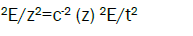
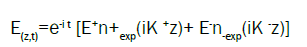
As it is known the eigenwaves corresponding to propagation of light in chiral LC along a spiral axes, i.e. the solution of the Maxwell equation [2].
 (2 )
(2 )
 (3)
(3)
where is the light frequency, n± are the two vectors of circular polarizations, (z) is the
dielectric tensor of the chiral liquid crystal [2,3], c is the light velocity and the wave vectors K± satisfy to the condition
K + - K -=, (4) (4)
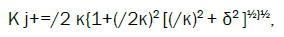
where is the reciprocal lattice vector of the LC spiral (=4π/p, where p is the cholesteric pitch). The wave vectors K± in the four eigen solutions (3) are determined by the eqn. (4) and the following formulas
 (5)
(5)
Where j numerates the eigen solutions with the ratio of amplitudes (E-/E+) given by the expression
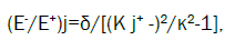
where κ=ω 0½/c, 0=( +)/2, δ=( -)/( +) is the dielectric anisotropy, and, are the principal values of the CLC dielectric tensor [2,3]. The eqns. (3)-(6) give exact analytical solution for the eigen waves in CLC propagating along the spiral axis. If we define the ratio of the dielectric constant imaginary part to the real part as, i.e.
=0(1+i). ( 7)
the mentioned formulas give an exact solution for absorbing CLC if >0 and amplifying CLC if <0.
At studying lasing in the structure schematically shown at the Figure 1 we assume that the parameter γ determining imaginary part of dielectric constant ε at the pumping frequency coinciding with the localized mode frequency is presented in the form ε=ε0(1+iγl) and is presented in the form ε=ε0(1-iγh) at the lasing frequency coinciding with the localized mode frequency. The absorption of light incident at the CLC layer presented at the Figure 1, is equal to 1- R-T, where R and T are the reflection and transmission coefficients of the layer. Reflection spectrum of the CLC layer shown at the Figure 1 close to the stop-band edge frequency is presented at Figure 2. The reflection minima at the Figure 2 give real parts of the descrete EM frequencies (which are munerated by integer numbers n, with n=1 for the closest to the stop-band edge EM frequency) [2]. A maximum of the pumping wave absorption corresponds to the minimum of lasing threshold (if the other parameters are fixed). So, to optimize the lasing one has to find a maximum of the pumping wave absorption. Figure 3 present unusual spectral dependencies (here and at all other figures δ(ν-1) is plotted at the frequency axis-the definition of ν is given below) of the absorption close to the EM frequencies and allow to find parameters of the structure ensuring absorption maximum of pumping wave (for example, the layer thickness Ll). The found by this way the layer thicknesses Ll corresponds to the maximum of the luminescence intensity at the pumping frequency coinciding with the localized edge mode frequency. Variations of the pumping intensity at this frequency allow to change the gain γh at the lasing frequency due to the variations of the lasing levels population inversion caused by this pumping wave intensity variations. To find a lasing threshold one has to solve dispersion equation
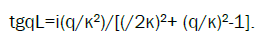 (8)
(8)

Figure 1: Schematic of the boundary problem for edge modes.

Figure 2: flection coefficient R close to the stop-band edge

Figure 3: Calculated frequency dependence for absorption (1-R-T)(l=300, l=L,=0.05): (a) γ=0.001, (b) γ=0.005.
The numerical solution of the eqn. (8) may be substituted by calculations of the reflection, transmission and absorption as functions of the parameter to be found as it is shown at Figures 4 and 5. The found by this way threshold gain γh at the lasing frequency can be reached at the corresponding (minimal) pumping intensity.

Figure 4: Calculated frequency dependence of R (l=300, l=L,=0.05) (a) close to the threshold gain for the first lasing edge mode (γ=-0.00565), (b) close to the threshold gain for the second lasing edge mode (γ=-0.0129); calculated frequency dependence of T (l=300, l=L,=0.05) (c) close to the threshold gain for the first lasing edge mode (γ=-0.00565), and (d) close to the threshold gain for the second edge mode (γ=-0.0129).

Figure 5: R (a), T (b) calculated versus the frequency (l=300, l=L,=0.05) for γ=-0.009, i.e., for the gain between the thresholds for the first and the second edge modes.
The highest efficiency of the pumping and the lowest value of the lasing threshold gain may be reached if the lasing occurs at the first EM frequency and the pumping wave is under conditions of the anomalously strong absorption effect. These may occur in a collinear geometry, however it demands a very special choice of the CLC parameters.
A regular way to reach the optimization is to use a non collinear pumping [4]. The corresponding value of the angle between the spiral axis and the pumping wave propagation direction is determined approximately as:
θ=arcos[ I/p ] ,( 9)
Where I and p are the lasing and pumping frequency, respectively.
An experimental realization of the discussed above DFB lasing optimization due to the oblique incidence of the pumping wave (transfer to a noncollinear lasing geometry) was reported in a study [5].
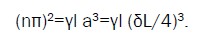
As was shown above in a general case the problem should be studied in a numerical approach, However, for thick CLC layers analytic expressions can be obtained. For thick CLC layers the real parts of EM frequencies ν (n is the EM number) are given by the expressions.
 (10)
(10)
For absorbing CLC the relationship between parameters ensuring the absorption maximum is [2]:
 (11)
(11)
The lasing threshold gain at the nth EM frequency γh
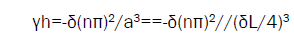 ( 12)
( 12)
As a result the cell thicknesses Ll, (Lh) corresponding to the absorption maximum of the pumping wave (and corresponding to the lasing threshold minimum at the localized edge mode frequency) are determined by the following relationships of the parameters:
 (13)
(13)
For optimization the absorption and lasing threshold simultaneously at the same sample the ratio Ll/Lh should be equal to 1. So the corresponding cnnection between parameters is:
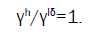 (14)
(14)
The obtained result shows that by variations of the pumping wave intensity resulting in variations of γh it is possible at some specific pumping wave intensity to satisfy the eqn. (14), i.e. to get an optimal lasing regime.
The obtained results explain the experimentally observed non-monotonic dependence of the DFB lasing threshold in CLC on the pumping intensity and present options for DFB lasing [1] optimization by a specific choice of CLC cell parameters. The presented above theoretical results have partially found an experimental confirmation. Figure 6 presents demonstration of the lasing optimization reached by temperature variations of the CLC pitch [6]. Along with the mentioned experimental optimization of lasing due to the pumping wave oblique incidence an lasing optimization due to the layer thickness variations was also reported [5,7]. Experimental observations of the anomalous absorption at the EM frequency revealing itself in luminescence were reported in previous studies [8,9]. The performed brief analysis of the DFB lasing at the edge mode frequencies has also shown the ways of optimization of DFB lasing experiment at defect structures by the way similar to the case of edge modes.

Figure 6: The lasing threshold gain at the nth EM frequency γh.
The work is supported by the RFBR grants 16-02-0295_a,16-02-0679_a.