Keywords
|
| Adaptive beam forming, Array factor, Directivity, Genetic algorithm, linear antenna array, Side lobe level. |
INTRODUCTION
|
| Usually the radiation pattern of a single element is relatively wide and each element provides low values of directivity. Antenna arrays increase the directivity without enlarging the size of single elements. Antennas arrays have been widely used in different applications are radar, sonar, and communications and as they are useful in high power transmission, reduce power consumption and enhanced spectral efficiency. Due to increased usage of electromagnetic spectrum, radiation pattern synthesis techniques, which allow placing of one or more nulls in the pattern in specified directions, are gaining technical importance. [1]. Array antennas have high gain and directivity compared to an individual radiating element [2]. Genetic algorithm (GA) is a powerful optimization method the synthesis of antenna array radiation pattern in adaptive beamforming. Adaptive beam forming is a signal processing technique in which the electronically steerable antenna arrays are used to obtain maximum directivity towards signal of interest (SOI) and null formation towards signal of not interest (SNOI) i.e. instead of a single antenna the antenna array can provide improved performance virtually in wireless communication [3]. The problem is to finding the weights of the antenna array elements that are optimum to provide the radiation pattern with maximum reduction in the sidelobe level and provide the maximum directivity towards the direction by modulating parameter M. The value of modulating parameter M is varying 0 to 1.the value of M is 0 when maximum directivity to a particular direction. When the value of M goes to high that time provide the radiation pattern with maximum reduction in sidelobe. |
PROPOSED ALORITHM
|
A. GENETIC ALGORITHM
|
| The genetic algorithm is a method for solving both constrained and unconstrained optimization problems that is based on natural selection, the process that drives biological evolution. The genetic algorithm repeatedly modifies a population of individual solutions. At each step, the genetic algorithm selects individuals at random from the current population to be parents and uses them produce the children for the next generation. You can apply the genetic algorithm to solve a variety of optimization problems that are not well suited for standard optimization algorithms, including problems in which the objective function is discontinuous, no differentiable, stochastic, or highly nonlinear. |
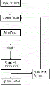
1. Genetic Algorithm Flowchart
|
| The most common type of genetic algorithm works like this: a population is created with a group of individuals created randomly. The individuals in the population are then evaluated. The evaluation function is provided by the programmer and gives the individuals a score based on how well they perform at the given task. |
| Two individuals are then selected based on their fitness, the higher the fitness, the higher and the chance of being selected. These individuals then "reproduce" to create one or more offspring, after which the offspring are mutated randomly. This continues until a suitable solution has been found or a certain number of generations have passed, depending on the needs of the programmer. |
| Selection – this is based on the fitness criterion to choose which chromosome from a population will go on to reproduce |
| Reproduction – The propagation of individuals from one generation to the next. |
| Crossover – This operator exchanges genetic material which is the features of an optimization problem. Single point cross over is used here. |
| Mutation – The modification of chromosomes for single individuals. Mutation does not permit the algorithm to get stuck at local minimum. |
| Stopping criteria – The iteration stops when the maximum number of cycles is reached. The grand minimum CF and its corresponding chromosome string or the desired solution are finally obtained. |
| Population - the number of chromosomes considered in one generation. |
B. Array Synthesis and solution:
|
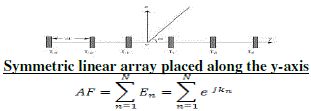
| An incident plane wave causes a linear gradient time delay between the antenna elements that is proportional to the angle of incidence. This time delay along the array manifests as a progressive phase shift between the elements when it is projected onto the sinusoidal carrier frequency. In the special case of normal incidence of the plane wave, all the antennas receive exactly the same signal, with no time delay or phase shift. In this work the antenna elements are assumed to be uniformly spaced, in a straight line along the y-axis, and N is always the total number of elements in the antenna array. The physical separation distance is d, and the wave number of the carrier signal is k =2?/λ. The product kd is then the separation between the antennas in radians. When kd is equal to ?(or d= λ/2) the antenna array has maximum gain with the greatest angular accuracy with no grating lobes. The phase shift between the elements experienced by the plane wave is kdcosθand è is measured from the y-axis, starting from the first antenna, as shown in Fig1. Weights can be applied to the individual antenna signals before the array factor (AF) is formed to control the direction of the main beam. This corresponds to a multiple-input-single-output (MISO) system. . In the process of formulation for the fitness function for minimizing the Side lobe level the antenna array [4][5][6], the array factor for N number of elements were considered and assumed that the elements of an array are spaced linearly and separated by λ/2 where λ is the wave length. |
 |
| Where En =ejkn and K= (nkdcosθ + βn) is the phase difference. βn is the phase angle. Consider an array of antenna consisting of N number of elements. It is assumed that the antenna elements are symmetric about the center of the linear array. The far field array factor of this array with an even number of isotropic elements (2N) can be expressed as |
 |
| Where amplitude of nth element, θ is the angle from broadside and is the distance between position of nth element and array center .The main objective of this work is to find an appropriate set of required element amplitude and that achieves interference suppression with maximum sidelobe level reduction. To find a set of values which produces the array pattern, the algorithm is used to minimize the following cost function |
 |
| WhereF0(θ) the pattern is obtained using our algorithm and is the pattern desired To find a set of values which produces the array pattern, the algorithm is used to minimize the following cost function |
 |
| = abs (H) , Where H is normalized field strength |
| The maximum directive gain is called as directivity of the antenna. The directivity of the antenna is defined as the ratio of maximum radiation intensity to its average radiation intensity and is denoted by D. |
 |
EXPERIMENT AND RESULT
|
| The antenna model consists of 8,16,20,24 elements and equally spaced with d =0.5λ along the y-axis. A continuous GA with a population size 20 and adaptive feasible mutation rate is run for a total of 100 generations unlike 500 generations as in using MATLAB and the best result was found for each iteration. The cost function is the minimum side lobe level for the antenna pattern and improving directivity by modulating parameter M. The value of modulating parameter M is varying 0 to 1.the value of M is 0 when maximum directivity to a particular direction. When the value of M goes to high that time provide the radiation pattern with maximum reduction in sidelobe. |
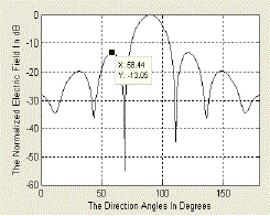
| Fig 3 shows that the antenna array with N = 8 elements has been normalized for a gain of 2.84dB along the angle 0°, modulating parameter M value is 0(low), the maximum relative side lobe level of -13.05 dB and directivity 13.39. |
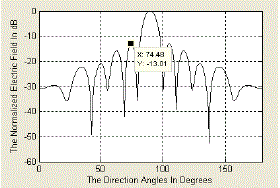
| Fig 4 shows that the antenna array with N = 16 elements has been normalized for a gain of 2.84dB along the angle 0°, modulating parameter M value is 0(low), the maximum relative side lobe level of -13.01 dB and directivity 16.53. |
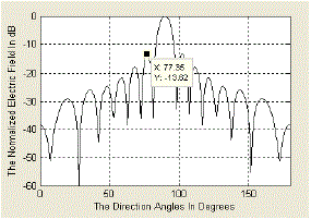
| Fig 5 shows that the antenna array with N = 20 elements has been normalized for a gain of 2.84dB along the angle 0°, modulating parameter M value is 0(low), the maximum relative side lobe level of -13.62 dB and directivity 17.55. |
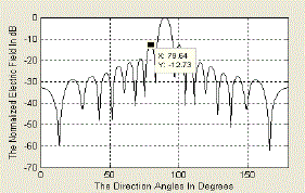
| Fig 6 shows that the antenna array with N = 24 elements has been normalized for a gain of 2.84dB along the angle 0°, modulating parameter M value is 0(low), the maximum relative side lobe level of -12.73 dB and directivity 18.38 |
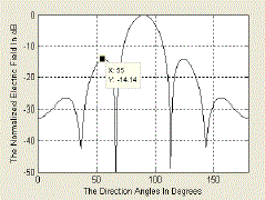
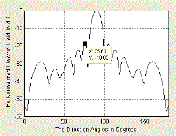
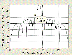
| Fig 7 shows that the antenna array with N = 8 elements has been normalized for a gain of 2.84dB along the angle 0°, modulating parameter M value is 1(low), the maximum relative side lobe level of -14.14 dB and directivity 13.11. |
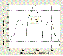
| Fig 8 shows that the antenna array with N = 16 elements has been normalized for a gain of 2.84dB along the angle 0°, modulating parameter M value is 1(low), the maximum relative side lobe level of -18.24 dB and directivity 15.94. |
| Fig 9 shows that the antenna array with N = 20 elements has been normalized for a gain of 2.84dB along the angle 0°, modulating parameter M value is 1(low), the maximum relative side lobe level of -18.82 dB and directivity 16.56. |
| Fig 10 shows that the antenna array with N = 16 elements has been normalized for a gain of 2.84dB along the angle 0°, modulating parameter M value is 1(low), the maximum relative side lobe level of -18.24 dB and directivity 15.94. |
CONCLUSION
|
| In this paper Genetic algorithm Solver in Optimization toolbox of MATLAB is used to obtain maximum reduction in side lobe level relative to the main beam on both sides of 0° and improve the directivity by modulating parameter M. The genetic algorithm is a method for solving both constrained and unconstrained optimization problems that is based on natural selection, the process that drives biological evolution. Adaptive feasible mutation with single point crossover showed the performance improvement by reducing the side lobe level below -10dB in most of the cases and also improves the directivity. The best result of -18.82.05 dB sidelobe is obtained for 20 elements in 100 generation of GA with best fitness value of 88.2984 and means fitness value of 91.2427and the best result of 18.38 directivity is obtained for 24 elements. |
Tables at a glance
|
 |
 |
| Table 1 |
Table 2 |
|
Figures at a glance
|
 |
 |
 |
 |
 |
| Figure 1 |
Figure 2 |
Figure 3 |
Figure 4 |
Figure 5 |
 |
 |
 |
 |
 |
| Figure 6 |
Figure 7 |
Figure 8 |
Figure 9 |
Figure 10 |
|
References
|
- Padmaja, N.Bala Subramanyam, N.Deepika Rani, G.Tirumala Rao, Linear Array Geometry Synthesis Using Genetic Algorithm for Optimum Side Lobe Level and Null, ISSN: 2277 – 9043 International Journal of Advanced Research in Computer Science and Electronics Engineering Volume 1, Issue 3, May 2012.
- C. A. Balanis, Antenna Theory Analysis and Design, 2nd Edition, John Willy & sons Inc, New York, 1997.
- Shraddha shrivastava and Kanchan cecil,”Optimatization of radiation pattern of linear antenna array using genetic algorithm”Recent Trends in Control, Communication and Computer Technology 25th Nov.2012, Nashik, ISBN: 978-93-82208-40-2.
- G. S. N. Raju, Antennas and Propagation, Pearson Education, 2005.[5] Stephen J.Blank, “Antenna Array Synthesis Using Derivative, Non-Derivative and Random Search Optimization”, IEEE Sarnoff Symposium, DOI 10.1109/SARNOF. 2008.4520115, pp 1-4, May 2008.
- Stephen J.Blank, “Antenna Array Synthesis Using Derivative, Non-Derivative and Random Search Optimization”, IEEE Sarnoff Symposium, DOI 10.1109/SARNOF. 2008.4520115, pp 1-4, May 2008.
- R.S.Elliott, “Antenna Theory and Design”, Prentice-Hall, New York 1981.
- Peter J.Bevelacqua and Constantine A.Balanis, “Optimizing Antenna Array Geometry for Interference Suppression”, IEEE Transaction on Antenna And Propagation, Vol.55, no.3 pp 637-641,March 2007.
- Peiging Xia and Mounir Ghogho, “Evaluation of Multiple Effects Interference Cancellation in GNSS using Space- Time based Array Processing”, International Journal of Control, Automation, and Systems, vol. 6, no. 6, pp. 884- 893, December 2008.
- B.Widrow et.al. “Adaptive antenna system”, IEEE.Proc 55(12) pp2143-2159 Dec 1967.
- T .S.Jeyali Laseetha, Dr. R Sukanesh “Synthesis of linear antenna array using Genetic Algorithm to maximize side lobe level reduction’’International Journal of Computer Application (0975 -8887),Volume 20- No 7,April 2011.
- T.T Taylor, “Design of line source antennas for narrow beamwidth and low side lobes”, IRE AP Trans 4 pp 16- 28 Jan 1955.
- Y.Lu and B.K Yeo, “Adaptive wide null steering for digital beam forming array with complex coded genetic Algorithm”, Proc.IEEE Phased Array System and Technology Symp pp 557-560 May 2000.
- R.L.Haupt, “An introduction to genetic algorithm for electromagnetic”, IEEE.
- E.T.Bayliss, “Design of Monopulse Antenna difference Patterns with low sidelobes”, Bell Syst. Tech.J.47 pp623- 650May-June 1968.
- C. A. Balanis, Antenna Theory Analysis and Design, 2nd Edition, John Willy & sons Inc, New York, 1997.
- R.A.Monzingo and T.W.Miller , “Introduction to Adaptive Arrays”, SciTech Publishing, Rayleigh NC 2003.
- R.L.Haupt, “Generating a plane wave in the near field with a planar array antenna Micrw.J.46 (9) pp 152-158 Aug 2003.
- Aritra Chowdhury, Ritwik Giri, Arnob Ghosh, Swagatam Das, Ajith Abraham and Vaclav Snasel,”Linear Antenna Array Synthesis using Fitness-Adaptive Differential Evolution Algorithm”, IEEE, 2010.
|