Keywords
|
| Edge detection, Delta frame, Background subtraction, Frame separation, Optical flow |
INTRODUCTION
|
| Optical flow estimation is very relevant; it has much application in today’s market, academic communities and in real time video processing requirements. In current scenario, optical flow estimation of a video sequence remains as a challenge. There is no accurate or specific method for this optical flow estimation. The existing method for this computation will not provide correct segmentation, so the obtained output will not give an exact image of the object. The most sensing applications require some form of digital signal processing so, these are implemented primarily on serial processors. Here a MATLAB based segmentation is done; then the further processing is to obtain an accurate image of the object. While the required output is achievable, low cost and low power consumption are achieved by the FPGA. Field programmable gate array contains a number of programmable logical components. So FPGA can be programmed according to our needs, quick development and prototyping is also possible. The FPGA is programmed to perform complex mathematical functions, making them suitable for any type of matrix applications. The main attraction FPGA is parallel architecture. |
| Optical flow estimation is very relevant; it has much application in today’s market, academic communities and in real time video processing requirements. In current scenario, optical flow estimation of a video sequence remains as a challenge. There is no accurate or specific method for this optical flow estimation. The existing method for this computation will not provide correct segmentation, so the obtained output will not give an exact image of the object. The most sensing applications require some form of digital signal processing so, these are implemented primarily on serial processors. Here a MATLAB based segmentation is done; then the further processing is to obtain an accurate image of the object. While the required output is achievable, low cost and low power consumption are achieved by the FPGA. Field programmable gate array contains a number of programmable logical components. So FPGA can be programmed according to our needs, quick development and prototyping is also possible. The FPGA is programmed to perform complex mathematical functions, making them suitable for any type of matrix applications. The main attraction FPGA is parallel architecture. |
PROPOSED SYSTEM
|
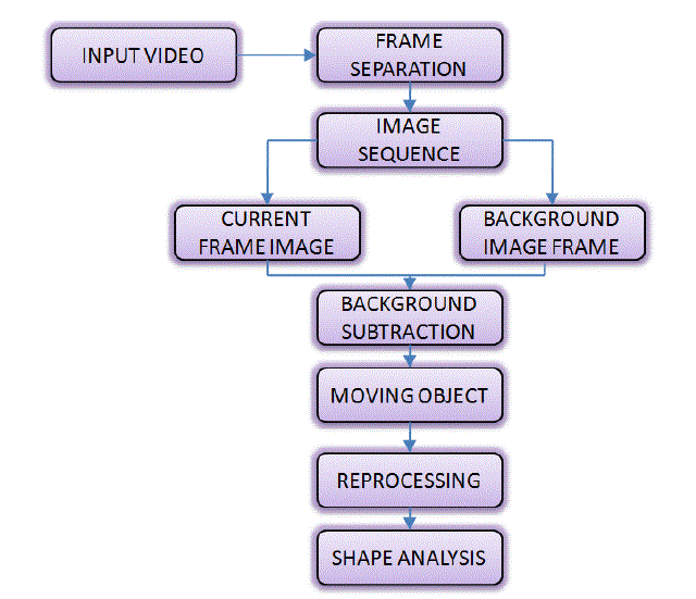
| This block diagram shows the proposed model of the system, to be executed. First a video is fed into a MATLAB program through the GUI, which will read .avi file, and convert it into frames. Each of the file is stored in an individual bitmap file, these bitmap files are stored in the order of occurrence of their arrival in the video. |
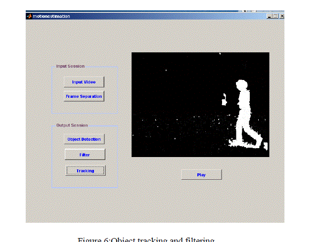
| The first frame is selected as background and the remaining frames are subtracted from the beginning, the resultant images used for target tracking, reorganization. Then this resultant image will determine whether any movement occurs between two frames, by this motion detection can be identified. When the motion is detected we have to reprocess the resultant image for getting an accurate image of the object. In reprocessing, the image goes through median filtering for reducing the noise in the image, before that a thresholding is applied for differentiating background and foreground. After reprocessing, it goes through shape analysis segment. For the analysis of shape, the image is subjected to edge detection procedure. By this the boundaries of the image detected and shape of the object is also clearly visible. |
WORKING OF THE SYSTEM
|
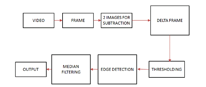
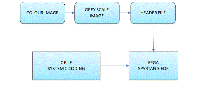
| The working of the system can be explained using the block diagram given here. The video is given to the proposed system, and then the video segmentation has taken place. 31 frames per second is obtained, the first frame obtained is taken as the background image, Each of the other frames taken as the foreground image for the subtraction purpose. The resultant image after the subtraction forms a delta shape. The delta frame image is gone through a brightness based threshold value for differentiating the foreground and background. Then median filtering is used for getting a noise free image. The median filtering value is obtained by examining the neighborhood pixel values. To obtain the precise shape of the image edge detection is employed. The sobel edge detection method is used, that will preserve all relevant details of the image. After going through this series of process the output will show in the visual basic display screen. The overall working of the system is explained with the help of figure 3. In this the hardware portion is also included. The FPGA has not enough memory to store a video clip. So the video clips converted into several frames. Frame separated bitmap files are in RGB format at a resolution of 640x480 pixels, in order to store this image in FPGA, resolution has to reduce; that is the grey scale conversion of the colour image. By this the pixel value lies between 0 and 255. Our system is designed using system C language, because it is a universally accepted language and also hardware interaction has is becoming easy. But the problem is the grey scale image is not detected by this system, and also size has to reduce. So as shown in figure 3 we convert the grey scale image into a header file format, the size is also reduced. When both the foreground and background image are converted into header file it will be stored in the SRAM of FPGA for further processing. Then the other system C based code is also loaded into Spartan 3 FPGA. The header file conversion of each image is shown in the figure 4.A MATLAB coding is used for this conversion. After this transition, it will reduce coherent effect and easily separate object from background. |
| The background subtraction is done between these images and a resultant image is formed .The resultant image is known as delta frame. This will eliminate the background and brings the object into focus, giving as information about shape and size. This also reduces the pixels that the arrangement has to process. After delta frame formation, in order to further enhance this, a threshold is applied. Here we fix a threshold value; above that value an object is detected; otherwise it will be the background. The object pixel will give a value 1 and background pixel give a value of zero after applying threshold value. The Initial value of the threshold is set by median or mean value. This is justified when an object pixel is brighter than the background. |
| The edge detection highlighting the edges of the image and the other parts becomes black. The points at which image brightness changes abruptly are typically termed as edges. Edge detection reduces the amount of data processed, it also filters out non relevant data in order to preserve structural properties of the data. The main application of this is to find out the information about shape and reflectance or transmission of an image. The last step of the process is applying a median filtering method; it to reduce the noise in the image; It will preserve useful details in the image. In this we are considering each pixel in the image and decide whether to represent it as its surroundings, and then replace the pixel value of the median value of surrounding pixel value. The median value is computed by sorting all pixel value from the neighborhood in numerical ascending order and replacing the pixel with middle pixel value. The main advantage of median filtering is more robust than mean, So single unrepresentative pixel in a neighborhood will not affect median value significantly, also better in preserving sharp edges. |
RESULT AND DISCUSSION
|
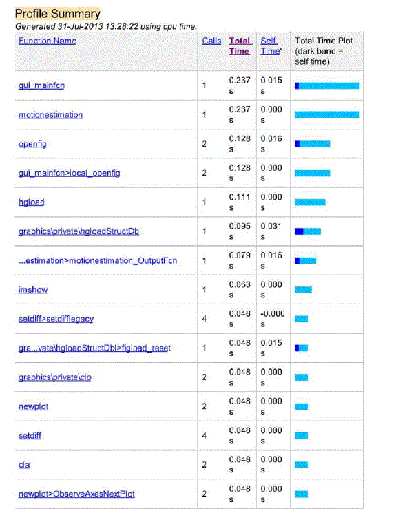
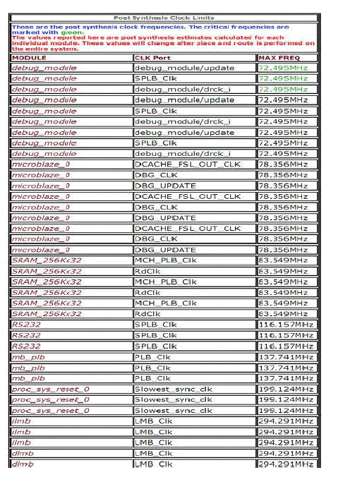
| This work is implemented on MATLABR2010a and the Parallel processor Xilinx FPGA Spartan III. The processing time obtained when implemented on MATLAB is 0.237 sec while the processing time obtained from Xilinx FPGA Spartan III is 13.79ns(72.495MHz). So this work optimize the processing time of optical flow detection in a video sequence. |
| A. Matlab Simulation Results |
| B. FPGA Implementation Results |
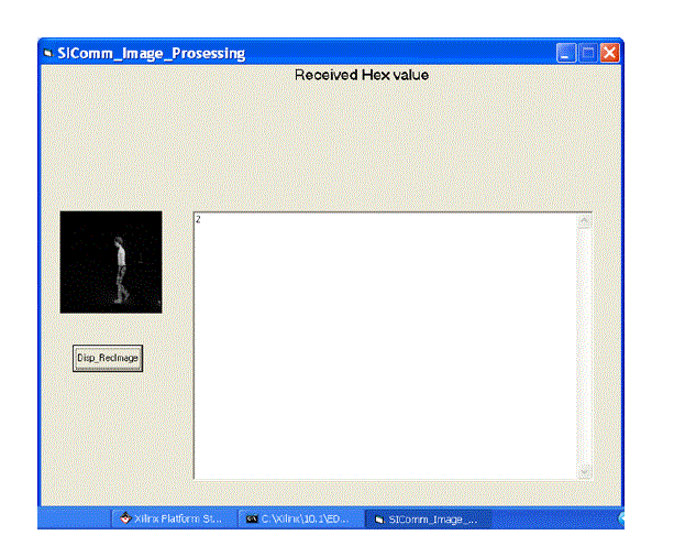
| Motion analysis is an important technology which modem bio-mechanics combines with computer vision and has been widely used in intelligent control, human computer interaction, motion analysis and virtual reality and other fields. The moving body detection is the most important part of the human body motion analysis, the purpose is to detect the moving human body from the background image in video sequences, and for the follow-up treatment such as the target classification, the human body tracking and behavior understanding, its effective detection plays a very important role. This design implementation required Xilinx Platform Studio (XPS) EDK 10.1 software platform along with MATLAB R2010a & Visual Basic Studio 6 to display images on computer screen. The conversion of true color image into gray scale image as well as resizing of image into (128 * 128) format was carried out using MATLAB R2010a Image Processing Toolbox. While coding of our design which include Background subtraction, Delta frame creation, thresholding, edge detection, filtering was carried out using Impulse C Language in XPS EDK 10.1. For a comparison between a parallel processor and serial processor the work is implemented on MATLABR2010a and the Parallel processor Xilinx FPGA Spartan III. The processing time obtained when implemented the work on MATLAB, is 0.237 sec while the processing time obtained from Xilinx FPGA Spartan III is 13.79ns. So this work optimize the processing time for optical flow motion detection. From the device utilization summery, utilization of 4 input LUTs is 77.7%. |
CONCLUSION
|
| In this research, a real-time and accurate method for detecting moving object is proposed, based on background subtraction. It uses a pixel network as the core of the architecture to implement segmentation with some degree of parallelism. An efficient colour segmentation algorithm for colour images are implemented using background subtraction. Experimental results show that our algorithm can produce good results. The traditional approach of segmentation using region growing method yields fruitful results only when the complexity is less. At last combine contour projection analysis with shape analysis to remove the shadow effect. Experiments show that the algorithm is fast and simple, able to detect moving object better and it has a broad applicability. |
Tables at a glance
|
 |
| Table 1 |
|
Figures at a glance
|
 |
 |
 |
 |
| Figure 1 |
Figure 2 |
Figure 3 |
Figure 4 |
 |
 |
 |
 |
| Figure 5 |
Figure 6 |
Figure 7 |
Figure 8 |
|
References
|
- Weiqiang Wang, Jie Yang, Wen Gao ,”Background and Segmenting Moving Objects from Compressed Video",IEEE transactions on circuitsand systems for video technology,vol. 18, NO. 5, MAY 2008.
- Du-Ming Tsai , Shia-Chih Lai ,”Independent Component Analysis-Based Background Subtraction for Indoor Surveillance", IEEETransactions On Image Processing, Vol. 18,No. 1, January 2009
- Javier Diaz, Eduardo Ros, Francisco Pelayo, Eva M. Ortigosa, Sonia Mota ,FPGA-Based Real-Time Optical-Flow System", IEEETransactions On Circuits And Systems For Video Technology, Vol. 16, No. 2, February 2006
- Yasuyuki Matsushi,Eyal Ofek, Weina Ge, Xiaoou Tang, Heung-Yeung Shum ,”Full- Frame Video Stabilization with Motion Inpainting",IEEE Transactions On Pattern Analysis And Machine Intelligence, Vol. 28, No. 7, July 2006
- Francisco Barranco, Javier Diaz, Eduardo Ros, and Begona del Pino, “Visual System Based on Arti_cial Retina for Motion Detection ", IEEETransactions On Systems, Man,And Cybernetics|Part B: Cybernetics, Vol. 39, No. 3, June 2009
|