Keywords
|
| IE3D,Miniaturization,CPW,Meandering,Planar antenna |
INTRODUCTION
|
PLANAR ANTENNA –MICROSTRIP PATCH ANTENNA
|
| A microstrip or patch antenna is a low profile antenna that has a number of advantages over other antennas It is light weight, inexpensive, and easy to integrate with accompanying electronics. While the antenna can be 3D in structure[1],the elements are usually flat hence their other name, planar antennas. Note that a planar antenna is not always a patch antenna.Patch antenna is also used for its for attractive features such as compatibility with Microwave Integrated Circuits and Monolithic Microwave Integrated Circuits[1]-[6]. This paper proposed a new design of Slotted CPW planar Microstrip Patch Antenna with 2 numbers of meander line for Wireless Systems applications.In proposed antenna,Feeding mechanism[5][10] plays an important role in the design of microstrip patch antenna.On one side there is the board dielectric, and on the top is usually air. The technique that has been developed to handle this challenge uses, as was mentioned above, the concept of effective relative dielectric constant, εeff.[5] This value represents some intermediate value between the relative dielectric constant of the board material, εr, and that of air (assumed equal to 1) that can be used to compute microstrip parameters as though the strip were completely surrounded by material of that effective relative dielectric constant. |
| One obvious advantage of the microstrip structure is the "open" line[9] which makes it very easy to connect components.The main drawback of this microstrip patch antenna is low bandwidth but there are some techniques to improve our patch antenna’s system bandwidth[6] |
FEEDING MECHANISMS:
|
| Feeding is a method of giving input signal to the antenna element to radiate electromagnetic signals in free space.Various feeding techniques are available for microstrip patch antenna [6] |
| The most popular feeding methods are, |
| ïÃÆÃË Strip line |
| ïÃÆÃË Micro strip line |
| ïÃÆÃË Slot line |
| ïÃÆÃË Fin line |
| ïÃÆÃË Coplanar Waveguide |
COPLANAR WAVEGUIDE AND MICROSTRIP LINE FEED:
|
| The popular two feedings are microstrip line and coplanar wave guide .Since the microstrip feed line is very simple in design and compact but the major drawback is its low bandwidth and poor efficiency.Hence coplanar wave guide (CPW) feed is most widely used in many antenna design.It will improve antenna’s efficiency,good return loss and hence bandwidth will be improve.Another advantage of CPW feed is adding of series and shunt components to the antenna is easier than microstrip feed lines.The comparative analysis of both microstrip and CPW feeds are discussed later. |
| The literature survey has been taken about miniaturization of planar antenna’s for various wireless applications such as fractal geometry,meta material.Various miniaturization have been analyzed so far.Among them meandering the current path is an efficient method to achieve size reduction and bandwidth.By introducing meandering line ,the electrical length of the antenna is increased. |
PROPOSED ANTENNA DESIGN
|
| The antenna structure discussed here is a slotted patch structure with meandering lines connected to both sides of slots.The overall antenna size is about (W*L*h) 25*34*1.6mm.The antenna is modeled over FR4 substrate which has dielectric constant of about 4.4 and loss tangent chosen is 0.02 .The proposed antenna structure and its parameters are shown below |

Fig no:1 (a) Proposed antenna structure (b) Design parameters |
PARAMETRIC ANALYSIS
|
| Parametric Analysis of the design has been discussed.Initially, a simple rectangle patch antenna design is made with a dimension of 25*34*1.6mm over FR4 substrate material which is widely used because of its low cost and easily available .Then the rectangle patch is etched at both the sides to made slotted structure .The etching is made to produce like “I” shaped antenna and this structure is excited by a microstrip feeding and the result is about poor return loss and hence the antenna bandwidth is much lower .In analysis 2,the same structure is excited by a Coplanar waveguide feed by introducing two ground plane at both sides of the strip feed which will act as a signal plane.As a result,Its bandwidth is much improved than strip feed.In final analysis ,meandering line is added to the structure .The antenna is now produced tri band wireless applications |
 |
| The return loss Analysis is given below which will describe the antenna‘s performance whether the designed antenna is suitable for wireless applications or not. |
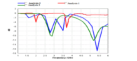
Fig no:3 Comparative Analysis of Return loss(dB) |
RESULTS AND DISCUSSION
|
| The proposed antenna design is designed ,simulated in Method of moments based software IE3D IE3D is a full-wave electromagnetic simulation and optimization package for the analysis and design of 3D and planar microwave circuits, MMIC, RFIC, RFID, antennas, digital circuits and printed circuit boards (PCB) .The important antenna parameters to evaluate its output characteristics are Return loss(dB),VSWR,antenna gain,Efficiency ,Bandwidth and its current distribution and Radiation pattern(2D and 3D). |
(1) RETURN LOSS(dB) and VSWR:
|
| Return loss of an antenna is an important parameter in any antenna design analysis.it gives the measure of how much amount of power will be reflected back from the antenna.it is represented in decibel.it should be kept as minimum as possible.the simulated result has good the return loss of below -10dB as shown in the figure.The return loss of the antenna can be calculated theoretically as follows, |
| Return loss(dB) = -20 log(ÃÂÃâ ÃÂóÃÂÃâ ) |
| The obtained return loss of -19 dB,-13.5dB and -25dB for the Triband wireless applications.Where ÃÂó is a reflection coefficient and it must be low as possible.The next important parameter is VSWR .it is voltage standing wave ratio which determines whether calculated bandwidth is useful or not .it also gives the ratio of peak maximum to peak minimum of the standing wave. |
| VSWR=Vmax/Vmin |
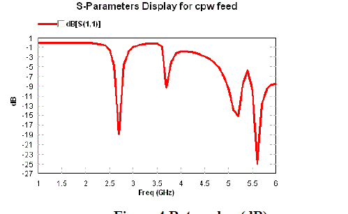
Fig no:4 Return loss(dB) |
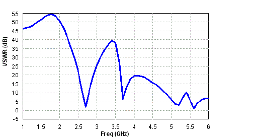
Fig no:5 VSWR display |
RADIATION PATTERN
|
| The 3D radiation pattern of an antenna is used to describe the 3 dimensional radiation characteristics.It includes type of pattern and coverage,flux density,radiation intensity and polarization of antenna.There are generally 3 types of pattern available like, |
Isotopic,
|
directional and
|
omni directional pattern.
|
| The radiation pattern obtained from the simulation is omni directional radiation pattern which has maximum radiation in all the directions with uniform gain.2D & 3D characteristics of the antenna is taken 2 Dimensional radiation patterns like antenna’s Elevation pattern and Azimuth pattern are analyzed and calculated for phi and theta values of 0 degree and 90 degree.The radiation pattern obtained froACKNOWLEDGEMENTm design is omni directional radiation pattern.omni directional pattern shows that the desired antenna produce uniform radiation in all the directions. |

Fig no 6:( a) 3D radiation pattern for E-total at 5.2 GHz ( b) Right hand polarizarion at 5.2 GHz band |
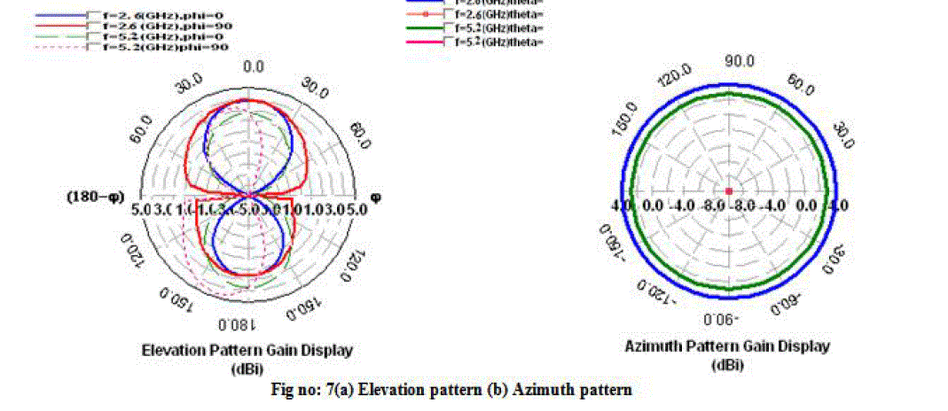 |
2D RADIATION CHARACTERISTICS
|
RADIATION EFFICIENCY:
|
| Antenna efficiency determines how much of power can the antenna will radiate the energy.the antenna efficiency should be high as possible. The simulated antenna radiation efficiency shows about maximum and the antenna efficiency about 49% for 2.6 GHz band,62%for 5.6GHz and 65% for 5.2GHz.figure no-8 shows antenna radiation efficiency |
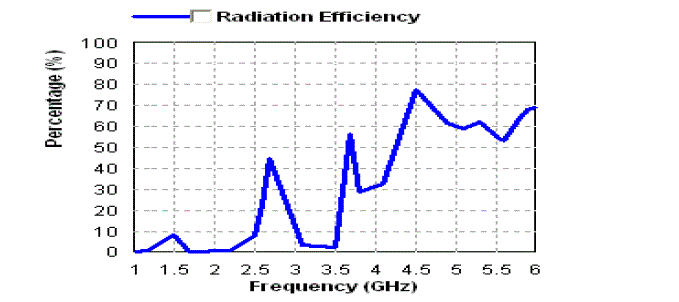
Fig no 8 : Antenna radiation efficiency |
(4).GAIN AND BANDWIDTH
|
| Gain of an antenna is defined as a measure of how much of energy does the antenna can extract from the wavefront .gain and directivity is related by the equation, G=η * D. The gain obtained from the simulation is about 2.5 dBi for 5.6 GHz band and 4dBi for 2.7 GHz frequency band wireless applications |
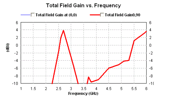
Fig no 9: Antenna Total Field Gain . |
| Bandwidth of the antenna is defined as the spectrum at which we can transmit and receive signals effectively .The calculated bandwidth of the design is about , (fu1) =2.85 GHz and (fl1) = 2.5GHz , Bandwidth of Band1 is 300MHz (fu2) =5.4 and (fl2) =4.8GHz, Bandwidth for Band2 is 600MHz (fl3) = 4.9GHz and (fu3) =5.48GHz, Bandwidth of Band 3 = 580MHz |
CURRENT DISTRIBUTIONOF THE ANTENNA
|
| Antenna current distribution is an important parameter to describe about its Electric field distribution during excitation .This structure shows that it has good Field distribution at its meander line at 5.2 GHz and on its edges at 2.6GHz band. |
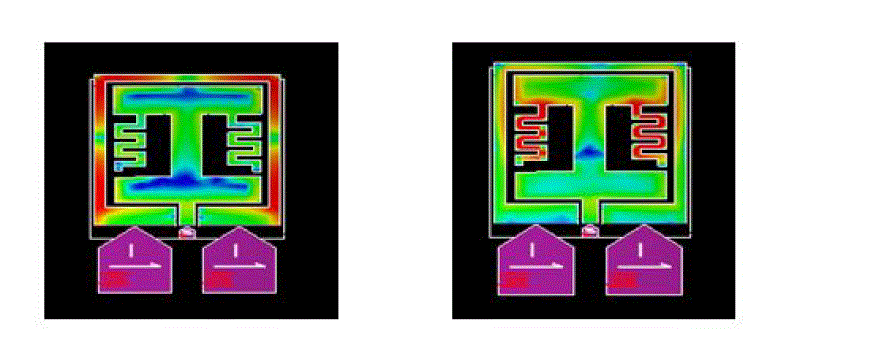
Fig no 10 :Antenna current distribution (a) at 2.6GHz and (b) at 5.2 GHz |
CONCLUSION
|
| A miniaturized slotted patch CPW fed antenna with meander line has been designed and its parametric Analysis also taken for wireless application (Tri band )of 5.2GHz WiMax/HIPERLAN,5.6GHz and also 2.6GHz band. In the band of operation , the antenna can generate a good omni directional radiation pattern and good radiation characteristics such as Return loss below -10dB .The simulated Return loss of about -19dB at 2.6GHz,-25dB at 5.6 GHz and -13.5 dB at 5.2 GHz and VSWR is below 2 and antenna radiation efficiency is about 49% for 2.6 GHz,,62% for 5.6GHz and 65% for 62%. The antenna is designed and simulated over IE3D version 14.0 .The total field gain of the antenna is obtained as 2.5dBi for 5.6GHz and 4dBi for 2.6GHz band. |
ACKNOWLEDGEMENT
|
| The authors I would like to thank heartly and proudly are professor. M.Shanmuga Priya.,M.E.,Ph.D.,and Head of the Department Dr.J.William.M.Tech.Ph.D.,for their help at the early stage of this work. |
References
|
- Akyildiz, Ian F., et al. "Wireless sensor networks: a survey." Computer networks 38.4 (2002): 393-422.
- .Hill, Jason Lester. System architecture for wireless sensor networks. Diss. University of California, 2003.
- . H. B. Salameh , T. Shu and M. Krunz "Adaptive cross-layer MAC design for improved energy-efficiency in multi-channel wireless sensornetworks", Ad Hoc Networks, vol. 5, no. 6, pp.844 -854 2007 .
- . IndraSurjati, Yuli KN and ArkyAstasari “MicrostripPatch Antenna Fed by Inset MicrostripRadioFrequency Identification (RFID)” 2010 Asia-Pacific Symposium on Electromagnetic Compatibility, April 12 - 16, 2010, Beijing, China.
- . X.-C. Yin, C.-L. Ruan, S.-G. Mo, C.-Y. Ding, and J.-H. Chu, A Compact Ultra-Wideband Microstrip Antenna With Multiple Notches, ProgressIn Electromagnetics Research, PIER 84, 321-332, 2008.
- .Huang, Jung-Tang, Jia-Hung Shiao, and Jain-Ming Wu. "A miniaturized Hilbert inverted-F antenna for wireles sensor network applications."Antennas and Propagation, IEEE Transactions on 58, no. 9 (2010): 3100-3103.
- .Si, Li-Ming, Weiren Zhu, and Hou-Jun Sun. "A Compact, Planar, and CPW-Fed Metamaterial-Inspired Dual-Band Antenna." (2013): 1-1.
- .Padhi, S. K., et al. "A dual polarized aperture coupled circular patch antenna using a C-shaped coupling slot." Antennas and Propagation, IEEETransactions on 51.12 (2003): 3295-3298.
- .J.Y. Chiou, J.Y. Sze and K.L. Wong, “A broad-band CPW-fed striploadedsquare slot antenna,” IEEE Trans. Antennas and Propag., Vol.51,No.4,April 2003, pp. 791-721.
- Padhi, S. K., et al. "A dual polarized aperture coupled circular patch antenna using a C-shaped coupling slot." Antennas and Propagation, IEEETransactions on 51.12 (2003): 3295-3298.
|