ISSN ONLINE(2278-8875) PRINT (2320-3765)
ISSN ONLINE(2278-8875) PRINT (2320-3765)
Shaik Rafi Kiran1, Dr.T.Sairama2, Dr.S.Varadarajan3
|
| Related article at Pubmed, Scholar Google |
Visit for more related articles at International Journal of Advanced Research in Electrical, Electronics and Instrumentation Engineering
Generally, the mechanical devices come with undesirable nonlinearities. Due to these nonlinearities the frequency domain system identification process in servo system seems to be a tough task. In the paper, particle swarm optimization (PSO) algorithm based hybrid technique is proposed for the frequency domain identification of servo system. The proposed hybrid technique is the combination of artificial neural network (ANN) and PSO algorithm. Initially, the system parameters are generated as a data set at different mass level by the artificial network. From the dataset, the PSO algorithm is used to optimize the system parameters such as pole, constant, DC gain and friction force etc. Then, the optimized parameters are applied to the system and the friction of system is analyzed in terms of velocity. The proposed identification method is implemented in MATLAB working platform and the deviation performances are evaluated. The system parameters identified by proposed method (PSO-ANN) is compared with actual system, GA-ANN, and adaptive GA-ANN.
Keywords |
| servo system, nonlinearity, identification, frequency domain, ANN, PSO. |
INTRODUCTION |
| To estimate a model for capturing system dynamics [11] [16], system identification process uses measured inputoutput. The intention and process of system identification [2] [4] is obtained by extracting mathematical models from physical systems. System recognition models can be constructed for varied stages and the control system can be supported by optimally choosing their outputs [1]. In recent times, a number of applications such as acoustic echo cancellation, channel equalization, biological system modeling and image processing have revealed great concern in nonlinear systems identification [3]. Due to friction force [8] some nonlinearity exists in hydraulic servo systems. Servo systems are frequently employed in the position control of friction [6] due to the capacity of servo systems to serve enormous driving forces and quick responses. Position reliant friction occurs [7] by commonly employing transmission mechanisms in elevated precision systems that achieve high-resolution movements. Therefore, friction has an authority on every regime of operations of a servo system [9]. |
| In high precision servo systems [5], friction is one of the most important drawbacks. The resistance experienced by a material in moving on top of another [12] [14] is known to be the frictional force. By the velocity and period of contact [13] the friction force will act. At low velocity motion [15] the control of friction force on servo-systems is notable above all. Using transfer function [17] the frequency domain model of nonlinear systems can be represented normally. In regard to the diverse frequency components a waveform is analyzed existing in the waveform by the frequency domain method [18]. The production of nonlinear system can be constructed by means of the frequency domain analysis of linear system [10]. The production frequency component is dissimilar from the contribution frequency component for nonlinear system [20]. Frequency domain system identifications believe the contribution and production signals to be periodic or time controlled inside the observation time [19]. |
| Frequency domain identification of servo system with friction force is restricted by the relocate function in the majority of the works. Since the transfer function target parameters of the plant are determined at random, the control techniques of such plants are unproductive and the friction force is physically selected. Consequently the determined parameters are unsuitable and choice of friction force takes considerable time. To overcome this matter, in this document, we suggest a hybrid technique for servo system identification in the frequency domain. The remaining part of the document is planned as follows. The model of a servo system and the proposed technique with necessary mathematical are illustrated in Section II, and the implementation results are discussed in Section III and Section IV concludes the paper. |
SERVO SYSTEM MODEL |
| Normally a plant, an actuator and some driving circuits are present in a servo system. The plant is driven by the actuator and both the components can be modeled as a second order transfer function. However, the system can be simplified as shown in Fig 1. In such servo system, static friction and coloumb friction are the two components. The modeling of friction force in servo systems in which s FïÃâ¬Ã« and s FïÃâ¬Ã are the static friction and ïÃâ¬Ã« Fc and ïÃâ¬Ã Fc are the coloumb friction. The system can be decomposed into linear and non-linear blocks. |
 Fig. 1: Block diagram of simplified system with friction |
| The plants to be identified are always assumed to be linear by the traditional frequency-domain identification methods that are based on covariance analysis and Fourier transform. But, this assumption is almost always invalid because of the presence of friction. Because, a plant can be represented by a linear block that describes the system dynamics in the feed forward path and a nonlinear block that describes the friction in the feedback path [2]. |
| A. Training of neural network |
The neural network is one of the artificial intelligence techniques which used for determining the target system parameters. Here, the feed forward neural network is used. The neural network consists of two phases: training phase and testing phase. Also, it consist of three layers: input layer, hidden layer and output layer. In training phase, the optimal data set trained based on the target data. The back propagation training algorithm is used for training the network. A pre-examined dataset is obtained from [2] and it is used as the training dataset D for neural network. The dataset D is comprised of input excitation magnitude as input and the system parameters, poles, constants, DC gain, minimum friction force and maximum friction force. The dataset D can be represented as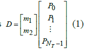 |
| where, m1 and m2 are the higher and lower excitation magnitudes and ïÃâ¬ÃÂ1 NT P is the system parameters. The feed forward network structure is described in Fig.2 which illustrated as follow, |
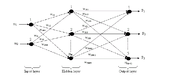 Figure 2: Structure of neural network. |
Back propagation training algorithm: |
| Step 1: Assign arbitrary weights generated in the interval ïÃÂÃâºwmin,wmaxïÃÂàto the hidden layer neurons and the output layer neurons. Assign unity value weights to each neuron of the input layer. |
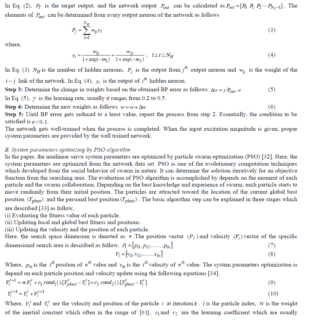
| Step 2: Determine the BP error by giving the training dataset D as input to the classifier as follows |
 |
| between [0 2] , rand1() and rand2() are the random value generated for each velocity update. The flow chart used for the proposed approach is illustrated in Fig.3 which described as follow, |
| System parameter optimizations steps: |
| Step(i): In the first step, the solution space, velocity (Vi ) and position (Pi ) are initialized. Here, solution space depends on the system parameters that are pole, constant, DC gain and friction force. These system parameters are depending on the higher (m1) and lower (m2 ) order excitation magnitude. |
| Step(ii): Then, the PSO parameters are specified in the second stage such as number of particles N, number of iterations t, inertia weight w, and learning coefficients c1and c2. |
| Step(iii): Check the objective of the specified parameters. If, the objective is violated, then go to next step. Otherwise, go to step(viii). |
| Step(iv): Update the iteration t=t+1 and evaluate the fitness function by the following equation. |
 |
| Step(v): Check probably, the function (equation (11)) minimized or not. If, minimized, go to next step. Otherwise, go to step(vi). |
| Step(vi): Then, evaluate each particle fitness value with the current and overall particle to identify Ypbest |
| Step(vii): Update the velocity and position of the particle. |
| Step(viii): If maximum iteration reached, then check the objective function is not violated and that value select as an optimal control parameter Ypbest = Ygbest. If its violated go to step(iv) and set t=0. Then, if maximum iteration not reached, then check the objective function is not violated and that value select as an optimal control parameter Ypbest = Ygbest. If, it’s violated go to step(iv). |
| The optimal control parameters are obtained from the PSO algorithm and the servo system is controlled. |
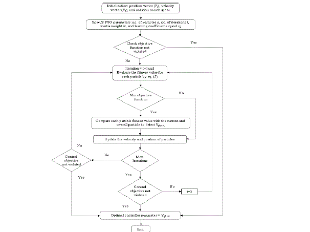 Fig. 3: Flow chart of PSO for optimizing system parameter. |
RESULTS AND DISCUSSION |
| The frequency domain identification of servo system with friction was implemented in MATLAB working platform. ANN and PSO algorithm based hybrid technique was used to identify the frequency domain of the system. The parameters are used for implementing the hybrid technique is tabulated in Table I. The performance of adaptive hybrid technique was tested by determining the system parameters for first order and third order servo system transfer function that are given in Eq. (12) and Eq. (13), respectively. As per the target data of system G1(s) andG2 (s) , the network is trained. Then, the linear block of the input excitation magnitude to the linear block and the output excitation magnitude from the linear block are analyzed. The implementation parameter of the PSO and ANN are tabulated in Table I. |
 Table I: The parameters and their values utilized in the PSO-ANN technique. |
| C. Analysis of system I: |
| In system I, the system output obtained from the proposed PSO-ANN identification technique is analyzed. The analyzed performance is compared with the actual system, GA-ANN, and adaptive GA-ANN based system identification technique. The comparison performance is illustrated in Figure 4, 5, and 6 respectively. Then, the system parameter of proposed PSO-ANN technique is compared with GA-ANN [31]. From equation (12), the system parameters that are obtained from the PSO-ANN technique and a frequency domain identification technique [2] are given in Table II. |
 |
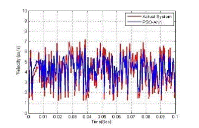 Fig. 4: System output comparison performance of from G1(s) . |
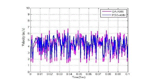 Fig. 5: System output comparison performance of from G1(s) . |
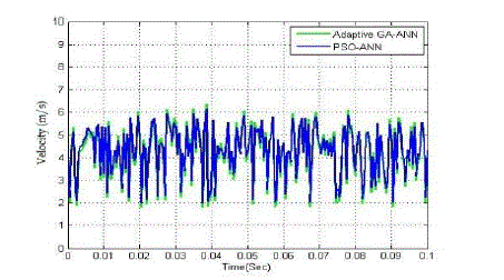 Fig. 6: System output comparison performance of fromG1(s) . |
 Table II: The target parameters, system parameters obtained from GA-ANN, adaptive GA-ANN, and PSO-ANN technique for the transfer function G1(s) |
| D. Analysis of system II: |
| The transfer function model of G2(s) is described in equation (13). Then, the system output attained from the PSO-ANN based system identification technique is analyzed. Then, the performance of PSO-ANN identification method is compared with actual system, GA-ANN, and adaptive GA-ANN based systems. The comparison performances are illustrated in Figure 7, 8, and 9 correspondingly. Using equation (13), the system parameters that are obtained from the adaptive hybrid technique and a frequency domain identification technique [2] are given in Table III. |
 |
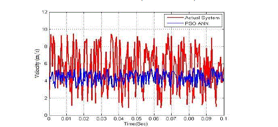 Fig. 7: System output comparison performance of from G1(s) . |
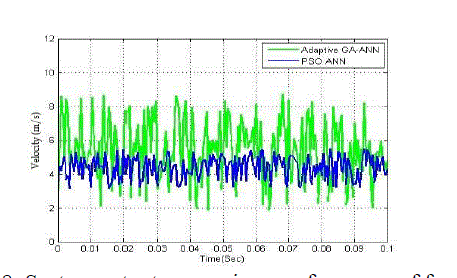 Fig. 8: System output comparison performance of from G1(s) . |
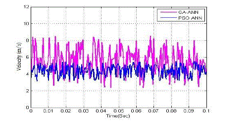 Fig. 9: System output comparison performance of fromG1(s) . |
 Table III: The target parameters, system parameters obtained from GA-ANN, adaptive GA-ANN, and PSO-ANN technique for the transfer function G2 (s) . |
Description: |
| The nonlinearity of proposed method revels from the comparative analysis. The PSO-ANN based identification technique provided the exact system parameter which close to target system. So, the nonlinearity of the system reduced that can be seemed in the comparative analysis. Also, the deviation analysis added more effectiveness to proposed system identification method. The table II and III contains the frequency domain identification parameters of existing technique identification technique, GA-ANN (Hybrid), adaptive GA-ANN (Adaptive Hybrid), and PSO-ANN techniques. From the identification parameters, the proposed method (PSO-ANN) and adaptive GA-ANN methods are provided better identification parameters. But, the nonlinearity of the proposed method is less than that adaptive GAANN method. |
CONCLUSION |
| The proposed PSO-ANN based identification technique was implemented. Then, the frequency domain identification performance of the proposed technique was tested with servo system with friction force. The identified parameters and the velocity performances were analyzed. The analyzed results of proposed method are compared with actual system, GA-ANN (Hybrid), and adaptive GA-ANN (Adaptive Hybrid). From the comparative analysis, the proposed method optimizes the system parameters better than those other techniques. So, the system provided less nonlinear when analyzed the velocity performance. Also, the deviation shows that, PSO-ANN method is performed well for identifying the servo system. |
References |
|