Keywords
|
| Radio propagation, Antenna gain, frequency band, Okumura model, Receiver, Base Transceiver Station (BTS), Mobile Station (MS). |
I. INTRODUCTION
|
| Wireless access network has becoming vital tools in maintaining communications especially at home and workplaces due to communication models. Propagation models help to understand the interferences in the network, which results in developing a well structured network with better quality. Those can be classified mainly into two extremes, i.e. fully empirical models and Deterministic models. There are some models which have the characteristics of both types. Those are known as Semi-empirical models. Empirical models are based on practically measured data. Since few parameters are used, these models are simple but not very accurate. The models which are categorized as empirical models for macro-cellular environment. These include Hata model, Okumura model, and Cost-231 Hata model. On the other hand, deterministic models are very accurate. Some of the examples include Ray Tracing and Ikegami model. As mentioned earlier, semi-empirical models are based on both empirical data and deterministic aspects. Cost-231W.I. model is categorized as a semi empirical model. All these models estimate the mean path loss based on parameters such as antenna heights of the transmitter and Receiver, distance between them, etc. These models have been extensively validated for mobile networks. Most of these models are based on a systematic interpretation of measurement data obtained in the service area [1][2][4][5]. |
II. LITERATURE SURVEY
|
| Medeisis and A. Kajackas formulated that Okumura-Hata model provided good results in urban areas but significant errors in rural areas which need necessary changes to the Okumura- Hata model through statical analysis. H.H. Xia, H.L. Bertoni & N. Madaya reported the loss measurements made in urban and sub - urban areas where the receiving mobile was driven along pre-selected Line of Sight. A. Neskovic, N. Neskovic & G. Paunovic worked on review of popular Propagation models for wireless communication channels in Macrocell, Microcell and Indoor system. . The model for urban areas was built first and used as the base for others. Clutter and terrain categories for open areas are there are no tall trees or buildings in path, plot of land cleared for 200-400m. For examples at farmland, rice fields and open fields. For suburban area the categories is village or highway scattered with trees and houses, few obstacles near the mobile. Urban area categories is built up city or large town with large buildings and houses with two or more storey or larger villager with close houses |
III. METHODOLOGY
|
| Accurate characterization of radio channel through key parameters and a mathematical model is important. Previous research described communication models (Okumura, Hata, Cost-231 etc.) on the basis of path loss. In this work the evaluation of communication models on the basis of signal strength, probability of error, path loss, BTS and MS antenna gain. The signal strength is described in terms of received power (Pr) at the receiver section. The comparison of communication models by taking probability of error into consideration is done by calculating probability of error (BER) of Binary phase shift keying (BPSK) modulation technique because in this work the BPSK modulation is taken for transmission for all communication models. The Base transceiver station (BTS) antenna gain and Mobile station (MS) antenna gain depends on the transmitter and receiver antenna height. |
IV. PROPAGATION MODELS
|
| A. OKUMURA MODEL |
| This is the most popular model that being used widely The Okumura model for Urban Areas is a Radio propagation model that was built using the data collected in the city of Tokyo, Japan. The model is ideal for using in cities with many urban structures but not many tall blocking structures. The model served as a base for Hata models. Okumura model was built into three modes which are urban, suburban and open areas. The model for urban areas was built first and used as the base for others. Clutter and terrain categories for open areas are there are no tall trees or buildings in path, plot of land cleared for 200-400m. For examples at farmland, rice fields and open fields. For suburban area the categories is village or highway scattered with trees and houses, few obstacles near the mobile. Urban area categories is built up city or large town with large buildings and houses with two or more storey or larger villager with close houses and tall, thickly grown trees[4][6][7][8]. |
| Formula for Okumura Model is expressed below: |
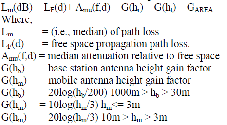 |
| GAREA: gain due to type of environment given in suburban, urban or open areas Correction factors like terrain related parameters can be added using a graphical form to allow for street orientation as well as transmission in suburban and open areas and over irregular terrain. Irregular terrain is divided into rolling hilly terrain, isolated mountain, general sloping terrain and mixed land-sea path. The terrain related parameters that must be evaluated to determine the various corrections factors. |
| B. HATA MODEL |
| Hata established empirical mathematical relationships to describe the graphical information given by Okumura. Hata’s formulation is limited to certain ranges of input parameters and is applicable only over quasi-smooth terrain. The mathematical expression and their ranges of applicability as [2][6][7][9][10]. |
| Carrier Frequency: 150 MHz ≤ fc ≤1500 MHz |
| Base Station (BS) Antenna Height: 30 m ≤hb ≤200 m |
| Mobile Station (MS) Antenna Height: 1 m ≤hm ≤10 m |
| Transmission Distance: 1 km ≤d ≤20 km |
| A + B log10 (d) for urban areas |
| Lp (dB) =A + B log10 (d) – C for suburban area |
| A + B log10 (d) – D for open area |
| Where: |
| A = 69.55 +26.161log10 (fc) – 13.82 log10 (hb) – a (hm) |
| B = 44.9 – 6.55 log10 (hb) |
| C = 5.4 + 2 [log10 (fc / 28)]2 |
| D = 40.94 + 4.78 [log10 (fc)]2 – 18.33 log10 (fc) |
| Where, a (hm) = |
| [1.1log10 (fc) –0.7] hm – [1.56log10 (fc) –0.8] for medium or small cities |
| 8.29[log10 (1.54 hm)]2 – 1.1 for large city and fc ≤ 200 MHz |
| 3.2 [log10 (11.75hm)]2 – 4.97 for large city and fc ≥ 400 MHz |
| C. COST-231 MODEL |
| Most future PCS systems are expected to operate in the 1800-2000 MHz frequency band. It has been shown that path loss can be more dramatic at these frequencies than those in the 900 MHz range. Some studies have suggested that the path loss experienced at 1845 MHz is approximately 10 dB larger than those experienced at 955 MHz, all other parameters being kept constant. The COST231-Hata model extends Hata's model for use in the 1500-2000 MHz frequency range, where it is known to underestimate path loss. The model is expressed in terms of the following parameters [7][8][11][12][13] |
| Carrier Frequency (fc) 1500-2000 MHz |
| BS Antenna Height (hb) 30-200 m |
| MS Antenna Height (hm) 1-10 m |
| Transmission Distance (d) 1-20 km |
| The path loss according to the COST-231-Hata model is expressed as: |
| Lp (dB) = A + B log10 (d) +C |
| Where; |
| A = 46.3+ 33.9 log10 (fc) – 13.28 log10 (hb) – a (hm) |
| B = 44.9 – 6.55 log 10 (hb) |
| C= 0 for medium city and suburban areas |
| 3 for metropolitan areas |
| D. Calculation of Path loss |
| The common representation formula of different communication models is [1][2][15] |
| PL (d) = PL (d0) + 10nlog10 (d/d0) ...…… (1) |
| d= Distance between Transmitter station and Mobile station |
| do= Reference point |
| n= Path loss exponent |
| E. Calculation of probability of error |
| Probability of error is a performance measurement that specifies the number of bit corrupted or destroyed as they are transmitted from its source to its destination. Several factors that affect probability of error include bandwidth, SNR, transmission speed and transmission medium [3][13][14][15][16] |
| Pe = ½{1-erf [sqrt (Eb/No)]} ……………….. (2) |
| Eb/No = Bit energy per noise spectral density |
| F. Calculation of signal strength |
| Received signal strength is a strength which is used to measure the power between the received radio signals. The received signal strength for Okumara, Hata and Cost-231 models is calculated as [17][20][21] |
| Pr = Pt + Gt + Gr –PL – A ……………….. (3) Where |
| Pr is received signal strength in dBm. |
| Pt is transmitted power in dBm. |
| Gt is transmitted antenna gain in dBm. |
| Gr is received antenna gain in dBm. |
| PL is total path loss in dBm. |
| A is connector and cable loss in dBm. |
| In this work, connector and cable loss are not taken into consideration |
| G. Calculation of BTS antenna gain |
| The antenna gain for free space model can be given as |
| G = 4^Ae/λ2 |
| Where |
| Ae = Effective aperture of an antenna |
| In this work the BTS antenna gain can be calculated as [5][10][18][19] |
| Gb = 20log (hb/200) ………………. (4) |
| Now the BTS antenna gain with correction factor can be calculated as: |
| Gb = 20log (hb/200) – cf |
| Where, |
| cf=31 For okumura model |
| cf = [1.1log10 (fc) –0.7] hm – [1.56log10 (fc) –0.8] |
| For Hata and cost-231model |
V. RESULT AND DISCUSSION
|
| A. Comparison of Okumura, Hata and Cost-231 model based on Path Loss |
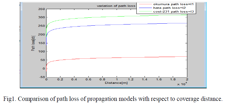 |
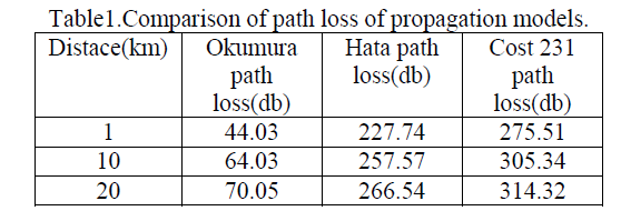
| In Sub –Urban areas the path loss in [db] of different commuication models for the same communication link when transmission distance is upto 10000 meters. Among three communication models such as Okumura model, Hata model and Cost-231 model, the Okumura model shows the least loss of signal i.e below 50db along the transmission ditance and Cost – 231 model shows highest path loss i.e about 300db. |
 ` ` |
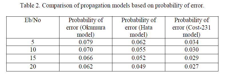
| B. Comparison of Okumura, Hata and Cost-231 models based on probability of error |
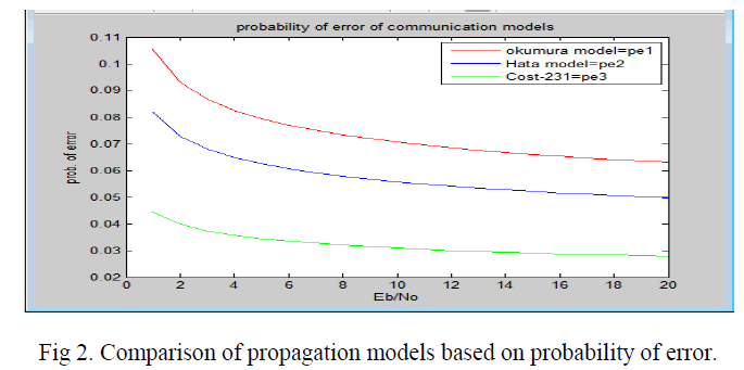 |
| The probability of error along the transmission distance for the same transmission link for different communication models such as Okumura model, Hata model and Cost-231 model. Among the three communication models Cost – 231 model shows the least Probability of error as compared to Okumura model which has the highest Probability of error. |
 |
| C. Comparison of Okumura, Hata and Cost -231 models based on signal strength |
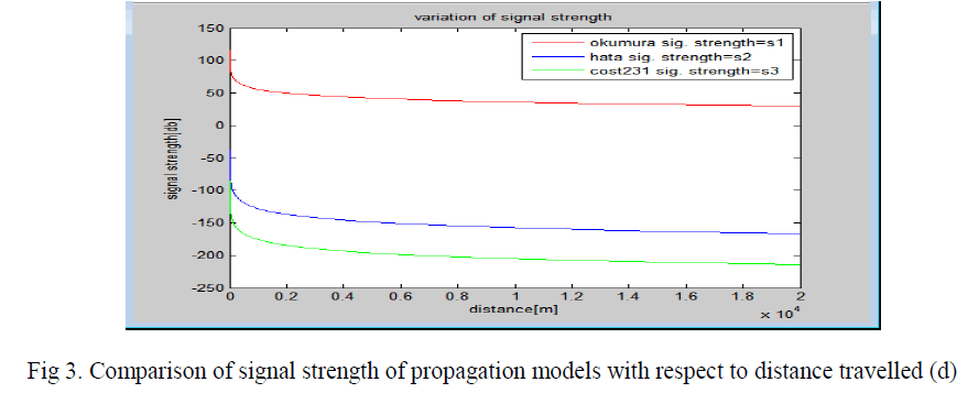 |
| In Sub –Urban areas the Signal Strength in [db] of different commuication models for the same communication link when transmission distance is upto 10000 meters. Among three communication models such as Okumura model, Hata model and Cost-231 model, the Okumura model shows the greatest Signal Strength i.e above 50db along the transmission ditance and Cost – 231 model shows least Signal Strength i.e about - 200db. |
 |
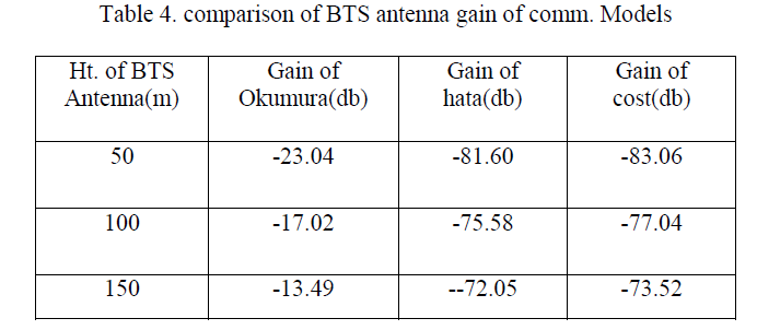
| D. Comparison of Okumura , Hata and Cost-231 models based on BTS antenna gain. |
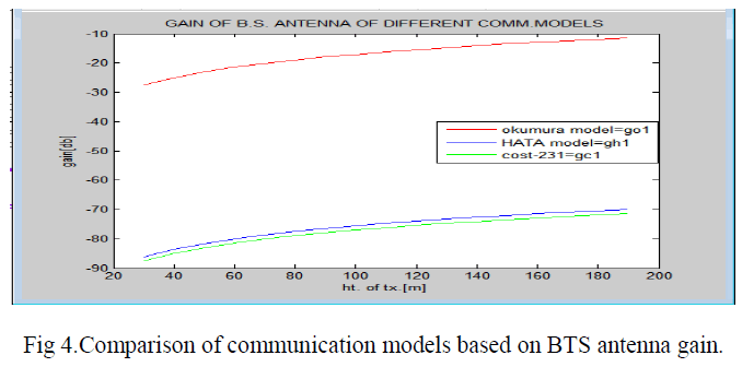 |
| The BTS Antenna Gain in [db] for three different communication models such as Okumura model, Hata model and Cost-231 model. The Okumura model shows the highest Antenna Gain [-10db] in comparison to other two communication models. Hata model and Cost – 231 model has almost the similar Antenna Gain i.e [--80db]. |
 |
| E. Comparison of propagation models based on MS antenna gain |
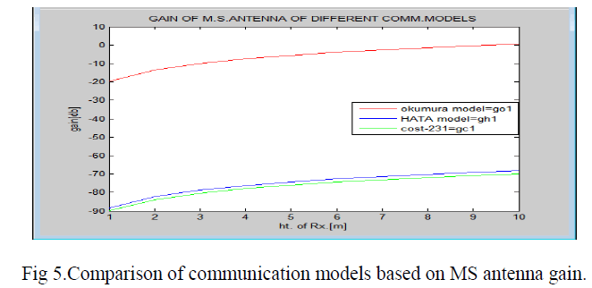 |
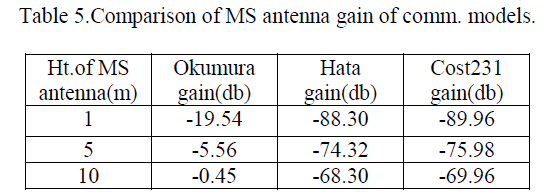
| The MS Antenna Gain in [db] for three different communication models such as Okumura model, Hata model and Cost-231 model. The Okumura model shows the highest Antenna Gain in comparison to other two communication models. Hata model and Cost – 231 model has almost the similar MS Antenna Gain. |
 |
VI. CONCLUSION
|
| In the present work, among the three communication models Okumura model shown the least path loss and Cost- 231model shown the highest path loss for specified transmission distance. As the path loss for Cost-231model is high so the probability of error is less and vice-versa Okumura model has high probability of error from eqn. (1) and (2). The individual gain of Okumura , Hata and Cost 231 model shows increasing trend. Among them the okumura model shows heighest gain i.e both BTS and MS antenna gain. As for as the signal strength parameter is considered Okumura model shown the highest results because of lowest path loss and Cost-231model shown the least signal strength among the communication models .The Hata model act as the intermediate between Okumura model and Cost-231 model for the results obtained from the path loss, signal strength and probability of error. |
| |
References
|
- M. Kumar, V. Kumar.& M. Malik., “Performance and analysis of propagation models for predicting RSS for efficient handoff”, Internationaljournal of advanced scientific research & technology, Vol. 1, ISSN: 2249-9954,Feb. 2012.
- H. K., S. Sahu. & S. Sharma , “Enhanced cost 231 propagations model in wireless network” international journal of computer application Vol.19, No. 06, (0975 – 8887), April 2011.
- H. Kaur, B. Jain & A. Verma, “Comparative performance analysis of M-ary PSK Modulation Schemes using Simulink”, International journalof ECE, IJECT, Vol. 2, Issue 3, September 2011.
- A. H. Ali & Md. R. A. Razak “Investigation of outdoor fading model over indoor environment”, International Conference on Business,Engineering and Industrial Applications (ICBEIA), IEEE 978-1-4577-1280-7/11/$26.00, 2011.
- Z. Nadir & Md. I. Ahmad, “Pathloss Determination Using Okumura-Hata Models with Field Measured Data”, International Journal ofEngineering Science and Technology,Vol. 2(6), pp.2008-2013, 2010.
- K. C. Amarasinghe, K.G.A.B. Peiris, L. A. D .M. D Thelisinghe, G. M. Warnakulasuriya, & A. T. L. K Samarasinghe, “Comparison ofPropagation Models for Fixed WiMAX System based on IEEE 802.16-2004”, Fourth International Conference on Industrial and InformationSystems, ICIIS 2009, IEEE, 28 - 31 December 2009
- T. K. Sarkar, Z. Ji , K. Kim, Ab. Medour& M. S. Palma, “A Survey of Various Propagation Models for Mobile Communication”, IEEEAntennas and Propagation Magazine, Vol. 45, No. 3, June 2003.Copyright to IJAREEIE 10.15662/ijareeie.2015.0402015 614
- V. S. Abhayawardhana, I. J. Wassell, D. Crosby, M. P. Sellars& M. G. Brown,” Comparison of Empirical Propagation Path Loss Models forFixed Wireless Access Systems”, IEEE , December 2003.
- V. Nikolopoulos, M. Fiacco, S. Stavrou, & S. R. Saunders, “Narrowband Fading Analysis of Indoor Distributed Antenna Systems”, IEEEantenna and wireless propagation letters, Vol. 2, 2003.
- M. Jeong& B. Lee, “Comparison between Path-Loss Prediction Models Wireless Telecommunication System Design”, Dep. Of Radio andBroadcasting system Engineering, Kyunghee University, IEEE, PP. 186-189, 2001
- H. Cavdar,” A Statistical Approach to Bertoni - Walfisch Propagation Model for Mobile Radio Design in Urban area, IEEE, PP. 279-283, 2001
- Spectrum Planning Team, “Investigation of Modified Hata Propagation Models”, IEEE, April 2001.
- T. Zwick , C. Fischer, D. Didascalou& W. Wiesbeck , “A Stochastic Spatial Channel Model Based on Wave-Propagation Modeling”, IEEEJournal on selected areas in communications,vol.18,pp. no.1 , jan. 2000.
- A.N, N.N & G. Paunovic, “Modern approaches in modelling of mobile radio systems propagation environment”, IEEE CommunicationsSurveys. Third Quarter 2000.
- M.D.A Jahn& W. Wiesbeck , “A comparison and verification of 2D and 3D ray tracing propagation models for land mobile satellitecommunications”, IEEE, 0-7803-6369,2000.
- A. Medeisis& A. Kajackas, “On the Use of the Universal Okumura-Hata Propagation Prediction Model in Rural Areas”, IEEE, 0-7803-571,2000
- K. Ayyappan& P. Dananjayan, “Propagation model for highway in mobile communication system”, Ubiquitous Computing and Communication Journal, Vol.3, No.4, PP. 61-66, 2000.
- P. Schneider, F. Lambrecht& A. Baier, “Enhancement of the Okumura-Hata propagation using detailed morphological and building data”,1996, IEEE.
- S. sarooshyari& N. Madaya, “An Introduction to mobile radio propagation and characterization of frequency bands” wirelesscomm.Technologies 16:332:559,1996
- H. H. Xia, H. L. Bertoni& L. R. Maciel, “Microcellular Propagation Communications in Characteristics for Personal Urban and Suburbanenvironments”, IEEE, transaction on vehicular technology Vol. 43, No. 3, Aug.1994.
- H. Hashemi, “Impulse RResponse Modeling of Indoor Radio Propagation Channels”, IEEE, Journal on selected areas in communications,Vol.11, No.7, Sept.1993.
|