Keywords
|
| Induction furnace (IF), performance analysis, harmonic measurements, Total Harmonic Distortion (THD), etc. |
I. INTRODUCTION
|
| Presently most of the steel melting industries in operation do use induction furnaces due to the significant advantages offered by them as compared to the other types of furnaces [1, [2]. However the major problem with this kind of furnaces from an electrical point of view is the inductive and non linear nature of the furnace load. This is responsible for generation of considerable harmonic distortion and pollution in the supply system. The cause is within the induction furnace design and operation itself, because it is a known fact that the order of harmonics and hence the magnitude of distortion depends upon the number of converter pulses used in the furnace power supply system. Secondly the situation is complex since the steel plant is composed of load that varies its consumption fast and thus this changes the harmonic composition. Also the way of connection and disconnection of power electronic components changes the harmonic composition too [3], [4]. |
| For controlling and preventing the harmonics/waveform distortion problems, rules and norms concerning permissible limits of voltage and current harmonic distortion do exist. However to comply with these legislations and reduce harmonic distortion below the established permissible level, proper corrective actions have to be taken. There are a number of harmonic mitigating techniques whose application varies from case to case and mainly depends upon the economy, suitability and compatibility of the mitigation technique to the customer system. The objective of this project study is to conduct thorough performance study of the existing setup of the steel melting unit under consideration so as to analyse the reasons for the problems faced by this unit. It is also to suggest the best possible solution keeping in mind the underlining constraints of minimum possible equipment modifications and investment as requested by the management of this industrial unit. |
| A. Details of the steel melting Unit under consideration |
| The steel melting unit under consideration is located at an industrial estate in the state of Goa, India. The single line diagram of the setup is as shown in the Fig. 1. |
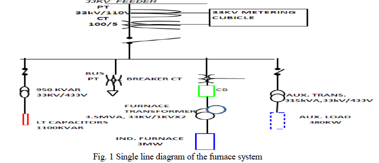 |
| The input supply from the utility distribution network which is 3 phase, 33kV at 50 Hz is stepped down to 1kV x 2 (double output) using a three winding phase shifting transformer with the primary winding connected in delta, secondary winding connected in star and tertiary winding is delta connected. This produces a phase shift of 300 which is necessary for the 12 pulse converter operation. The power from the transformer is delivered through the double bus duct to the 12 pulse Converter section (Generator panel). A capacitor bank of 1100 kvar is connected through a 33kV/433V step down transformer for power factor improvement purpose supposedly from 0.93 to unity. The LT auxillary load comprises of overhead magnetic cranes, ID fans, cooling tower motor, compressors, pumps, press motor, etc. It is supplied through the auxillary distribution transformer of 315kVA capacity. The general block diagram of the induction furnace and its associated components is as shown below in Fig. 2. |
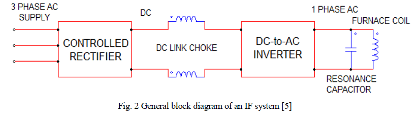 |
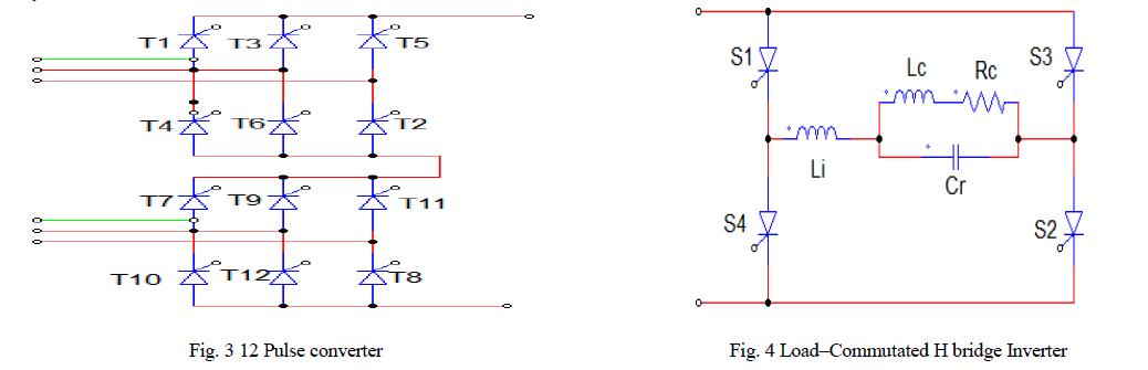
| The secondary winding feeds a 6 pulse thyristor controlled rectifier and the tertiary feeds another identical 6 pulse rectifier with both rectifiers connected in series. Hence the rectification has a 12-pulse configuration as shown in Fig. 3 below. The output of each 6 pulse converter is around 1350 -1500V DC. The combined output of both the series connected converters which is 2.7 to 3kV DC is passed through filtering choke coils for improving the direct current characteristics. This is then supplied as the input to the inverter section which consists of a Parallel Resonant/Load– Commutated H bridge Inverter (as shown in Fig. 4 below) that produces a 3kV single phase AC output at medium frequency of 500 Hz [5]. |
 |
| Further this power is then fed to the IF coil of the double crucible coreless induction furnace (only one crucible is operated at a time). A capacitor bank of 44668kvar is connected in parallel with the induction furnace coil to achieve a controllable resonance of the coil. The coil has an approximate consumption of 3000 kW. The induction furnace works in the resonant frequency range from 400-500Hz. |
 |
| C. Problem identification |
| For the purpose of this case study a suitable steel/scrap melting unit employing an induction furnace with 12 pulse converter circuit in its power supply scheme and which is located in the state of Goa, India, was selected. The monthly electricity bill of this unit amounts to around Rs. 60-65 lakh which is almost 25% of the monthly production cost of this unit. Actually as per the furnace supplier standards the specific consumption for melting only steel scrap is 500kWh/T [1]. However depending upon the proportion of raw material mixture (which here is mostly 25% steel scrap mixed with 70-72% Directly Reduced Iron and 4% Pig Iron), the specified energy consumption may increase up to 600-700kWh/T. But as per the available records, the average consumption here varies between 750-800kWh/T. This high energy consumption is a matter of concern to the management of this unit and the reasons for the same were felt necessary to be investigated and addressed at the earliest. Secondly, the management was interested in having suggestions/ proposed solution for overcoming the problem of excessive power consumption. Thirdly and more importantly the management expected that this solution be implemented with minimum possible modifications in the existing system setup so that the investment required could be kept down to the minimum. |
II. RESEARCH METHODOLOGY
|
| The methodology adopted for achieving the objectives of this performance study can be segregated into 3 main stages as proposed below:- |
| 1) Conducting the onsite performance analysis of the existing IF system as per the actual operations and loading conditions at the site. |
| 2) Identifying the problem and investigating the reasons for the same. |
| 3) Suggesting a suitable and economical solution. |
| A. On site performance analysis |
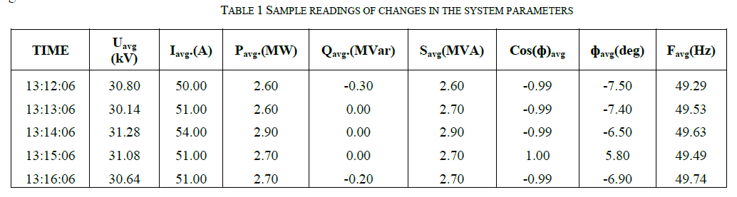
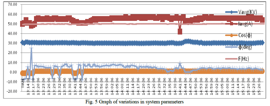
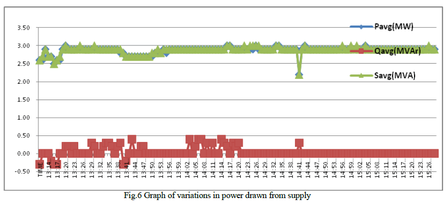
| For the purpose of performance analysis and harmonic measurements, the Point of Common Coupling (PCC) was located near the metering CT and PT, on the incomer side of 33kV/1kV furnace transformer. The readings were recorded by using a power analyser meter, over varying conditions of loading, operations and over several numbers of full melting cycles each of which ranges from around 2-2.5 hours [6]. The time interval between subsequent readings has been set to 1 minute. Thus the quantum of the readings gathered over one heating cycle and hence the size of tables of readings is quite large, making it difficult to present it in totality in this paper. Hence for the purpose of feasibility and convenience, the analysis of the recorded readings has been done separately but some sample readings are as shown in the Table 1 below and graphical representation of the complete set of actual readings is as shown below in Fig.5 & 6. |
|
 |
 |
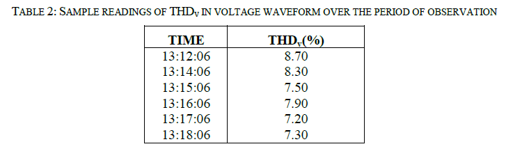
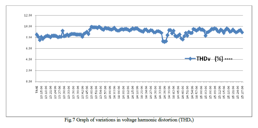
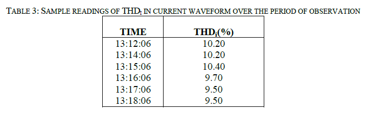
| However in order to find out the root cause of excessive electrical power consumption, it becomes necessary to perform the harmonic measurements and analysis of this system separately. The sample readings of induced voltage and current harmonics (THDv & THDi) obtained from the harmonic measurements have been tabulated in the Table. 2 and 3 below and the actual set of readings are graphically represented in Fig. 7 and 8 below. |
 |
 |
 |
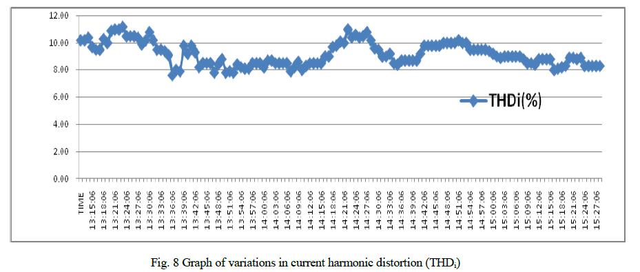 |
| It is observed from the Fig.7 that the voltage waveform is distorted to a very large extent. The average value of the THDv varies from 7.2% to 9.9%. This is very much higher than the 5% limit laid by IEEE standard 519-1992 for systems with voltage levels below 69kV. Also Fig.8 indicates that total current harmonic distortion (THDi) varies from 7.60% to 11.20%. This need to be verified for its acceptable level based on the calculation of the Short circuit ratio & TDD as well as based on magnitudes of individual current harmonics. The short circuit ratio for this particular system has been calculated and found to be 64.52. This short circuit ratio lies in the range of 50 to 100. Hence referring to the IEEE std. 519-1992, the acceptable TDD limit is 12% for a 6 pulse converter and 16.97% for a 12 pulse converter. The TDD for this existing system has been calculated and found to be 16.42% which is just within the limits [7], [8]. |
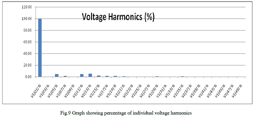
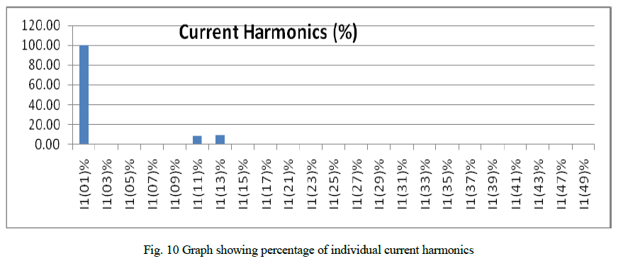
| Further it is also necessary to verify the order and magnitude of individual voltage and current harmonics present. Hence readings of the same have also been recorded for analysis purpose under different loading conditions and over the whole range of heating cycles. One of these readings has been plotted graphically as shown below in Fig.9 and 10. |
 |
 |
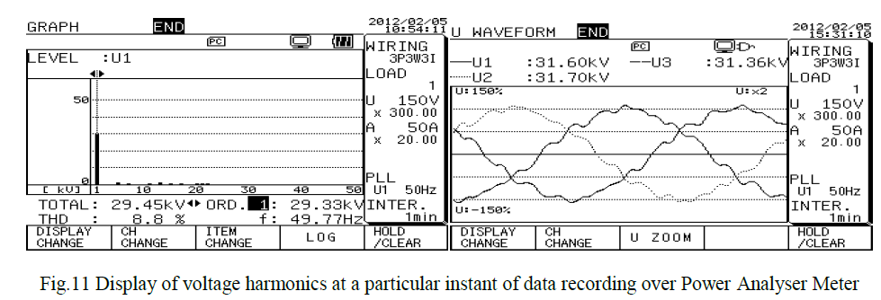
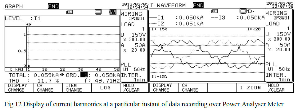
| The displays of voltage and current harmonics recorded at a particular instant of data recording over the Power Analyser Meter as shown below in Fig.11 and 12 are also in conformity to the above obtained results [9]. |
 |
 |
III. OBSERVATIONS
|
| 1) It is observed from the Fig.5 and 6 that the supply voltage varies between 29 to 32.07kV. Supply current varies between 52-57A. The input power varies between 2.6-3MW, power factor varies from 0.99 lag to lead and maintained at unity for majority of the operation period. |
| 2) As seen from the Fig.7, the average value of the THDv varies from 7.2 to 9.9%. This is very much higher than the 5% limit laid by IEEE standard 519-1992 for voltage levels below 69kV. |
| 3) The observation of the individual voltage harmonics as seen from Fig.9, indicates that 5th, 11th and 13th harmonics are dominantly present and have magnitudes in the range of 4 to 7% which are beyond the permissible limits of 3% laid by IEEE standard 519-1992. The 7th, 15th, 17th, 19th, 23rd, 25th and 29th are also present considerably but have magnitudes within the limits. While 31st, 33rd, 35th are occasionally appearing. All higher order harmonics are absent. |
| This indicates that the system voltage has been considerably affected and these individual voltage harmonics and THDv urgently need to be brought down within the acceptable limits. |
| 4) As seen from the Fig. 8, the average value of THDi varies between 7.60 to 11.20%. However the TDD which will give the true representation of current harmonics has been calculated and found to be 16.45% which is just below the limit of 16.97% for a 12 pulse converter [7], [8]. |
| 5) As per IEEE std. 519-1992, harmonic value for 11≤h≤17 should be less than 6.36% [7], [8]. But measured values as represented in Fig. 10, show the dominant presence of large 11th and 13th current harmonics. Their values vary between 7.20 to 10.90% which is higher than the allowable limit. All other harmonics are absent. |
| 6) The triplen voltage and current harmonics are not present, which may be mainly due to the use of Three winding Furnace transformer with Dyn11Dd0 configuration [9]. |
| The outcome of the onsite measurements and analysis have shown that the above results are as expected for a 12 pulse converter system and that the major cause of the problems faced by this steel melting plant lies in the design and composition of the power conversion unit of the induction furnace itself. Hence our attempts should be concentrated towards mitigation/reduction of 11th & 13th current harmonics below permissible limits 3% and reduction of individual voltage harmonics as well as THDv below 3% and 5% respectively. |
IV. SUGGESTIONS& CONCLUSIONS
|
| A. Suggesting possible solutions for the harmonic mitigation |
| The possible solutions that could be applied for the mitigation of voltage and current harmonics in the present case are as follows:- |
| 1) Design and installation of a 24 pulse converter to eliminate harmonics below the order of 23. |
| 2) Design and installation of suitable tuned harmonic filter circuit [11]. |
| 3) Use of proper phase shifted transformer. This is already being used. |
| 4) Suitably controlling the system impedance to cause resonance at required frequency other than harmonic frequency. |
| 5) Proper capacitor bank design to prevent resonance at any harmonic frequency. This is already partially satisfied. |
| 6) Adopting selected harmonic injection method and improved PWM techniques. |
| B. Finalizing/concluding mitigation technique for the present case |
| The present project study is aimed at reducing the harmonic levels present in the power system under consideration by way of eliminating the harmonic generation itself rather than allowing harmonic generation and then trying to filter them out. Thus it may be concluded that the proposed solution of design and installation of a 24 pulse converter appears to be the suitable and more feasible option in the present scenario mainly due to the following reasons:- |
| 1) Lower order harmonics are difficult to mitigate. But by employing a 24 pulse converter, harmonics below 23 (h<23) would get eliminated/reduced automatically. |
| 2) Since it is possible to form 24 pulse converter by connecting another 12 pulse converter in series with the existing one, thus there would be no need for scrapping the existing system but only few modifications may be required to be done. This would reduce the installation cost and time at large. |
| 3) As per IEEE standard 519-1992, if the harmonic producing loads consist of converters with pulse number q higher than 6, then the permissible harmonic limits are raised by a factor equal to . Thus for the 24 pulse converter, the permissible harmonic limits would be raised by a factor equal to 2 [7], [8]. This is a very significant advantage of employing 24 pulse converter. |
| C. Expected improvements due to replacement of 12 pulse converter with 24 pulse converter |
| For verifying the effects of employing a suitable 24 pulse converter as replacement for existing 12 pulse converter, a 24 pulse converter which is tailor made to suit the existing system is simulated under MATLAB SIMULINK environment and the simulation results are analysed and verified [12], [13]. Following inferences are drawn:- |
| 1) Considerable reduction in the magnitude of the input current drawn from the supply source (almost 7A on the 33kV side in the present case). This further leads to following benefits [14] :- |
| i. Reduction in the kVA demand. |
| ii. Reduction in the energy (kWh) consumption. |
| iii. Reduction in the I2R losses leading to improved system efficiency and reduced system cooling requirements. |
| 2) Significant reduction in the system voltage and current harmonic distortions which further leads to following benefits:- |
| i. Improvement in voltage and current waveform shapes nearing sinusoidal shape. |
| ii. Reduction in the THDv and THDi limits to below 5% and 3% respectively. |
| iii. Elimination or reduction of harmonic orders below 23 to within permissible limits. Hence harmonic filter for filtering lower order harmonics would be either not required or if required, then the size and cost of filter circuit would be reduced considerably. |
| 3) Improvement in the operating power factor from 0.95 lag for 12 pulse converter to 0.975 lag for 24 pulse converter. Hence numbers of power factor improvement capacitors and their cooling is reduced, thus reducing the installation cost. |
| 4) Improvement in the insulation life and performance of transformer, motors and capacitors. |
| The solution proposed above in this paper is very much feasible, attractive and it is technically as well as commercially viable for its adoption keeping in view the wider perspective of energy conservation and power quality. |
References
|
- Electrotherm (India) Ltd., “Service Engineers Manual”.
- Mishra. G &.Mehrotra K.K, (2006) “Energy Efficient Technology Holds Brighter Future for Indian Induction Furnace Industry”, All IndiaInduction Furnace Association (AIIFA) Journal.
- Zamora, I. et al, “Harmonic Distortion in a Steel Plant with Induction Furnaces”.
- Dugan, R. C., Conrad, L. E., (1999), “Impact of Induction Furnace Inter Harmonics on Distribution Systems” Transmission and DistributionConference, IEEE, Vol. 2, pp 791-796.
- Suresh, A., Reddy, R. S., (2011), “Parallel Resonance Based Current Source Inverter for Induction Heating”, European Journal of ScientificResearch, Vol.58, No.2, pp 148-155.
- Ellis, R. G., (1996), “Harmonic: Analysis of Industrial Power Systems”, IEEE Transactions on Industry Applications, Vol.32, No. 2, pp 417-421.
- IEEE, “Recommended Practices and Requirements for Harmonic Control in Electrical Power Systems, IEEE Standard 519-1992 (Revision ofIEEE Std. 519-1981)”.
- McGranaghan, Mark (1998), “Overview of the Guide for Applying Harmonic Limits on Power Systems - IEEE P519A”, 8th InternationalConference on Harmonics and Quality of Power (ICHQP 1998), Vol. 1, pp 462-469.
- Diagnostic, Cables & Capacitors Division, Central Power Research Institute (CPRI), Bangalore, (2006), “Report on Harmonic Measurementsof 33 kV HT Consumers- Ferro Alloy Industries for Electricity Department Goa”, pp 118-134.
- Jabbar, R. A., et al, (2008), “Voltage Waveform Distortion Measurement Caused by the Current drawn by Modern Induction Furnaces”, 13thInternational Conference on Harmonics and Quality of Power, (ICHQP 2008), pp 1-7.
- Wakileh, G. J., (2007), “Power Systems Harmonics Fundamentals, Analysis and Filter Design”, Springer, First Indian Reprint 2007.
- Zamora, I., et al, (2003), “Simulation by MATLAB/Simulink of Active Filters for Reducing THD Created by Industrial Systems”, Power TechConference Proceedings IEEE Bologna, Volume: 3.
- Hernadi, A., et al, (2008), “Modeling and Simulation of 6-Pulse and 12-Pulse Rectifiers under Balanced and Unbalanced Conditions withImpacts to Input Current Harmonics”, Second Asia International Conference on Modeling & Simulation (AICMS 08), pp 1034-1038.
- Jabbar, R. A., et al, (2008), “Operational and Economic Impacts of Distorted Current drawn by Modern Induction Furnaces”, AustralasianUniversities Power Engineering Conference (AUPEC'08), pp 1-6.
|