The Corner reflector antenna is designed using antenna magus tool. The system efficiency depends on the spacing between the vertex of the corner reflector and the feed element that is S. The spacing affects gain and bandwidth. Spacing S is thus selected as a compromise between gain and bandwidth. The antenna is designed varying i) spacing between source and reflector to obtain maximum gain of 16.5dB ii) reflector angle to obtain maximum gain of 16.99dB iii) reflector length for maximum gain of 15.36dB.
Keywords |
| Antenna Magus, Bandwidth, Corner reflector antenna, Dipole, Frequency, Gain, Reflector angle,
Reflector length, Spacing. |
INTRODUCTION |
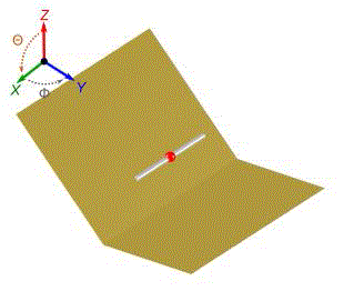
| The corner-reflector antenna is made up of two plane reflector panels and a dipole element. This arrangement
prohibits radiation in the back and side directions and hence makes the antenna more directional. The feed element for
the corner reflector is almost always a dipole or an array of collinear dipoles placed parallel to the vertex a distance s
away, as shown in Fig1. To obtain a greater bandwidth the feed elements are thick cylindrical or biconical dipoles
instead of thin wires. The aperture of the corner reflector (D) is usually made between one and two wavelengths( λ<D<2λ)
. The feed-to-vertex distance (s) is usually taken to be between a third and two-thirds of the wavelength(λ/3<s <2λ/3)
The corner reflector antenna is designed using antenna magus tool. |
| “Antenna Magus is the first antenna design tool of its kind. Its huge searchable collection of antennas can be explored
to find, design and export models of designed antennas to CST MICROWAVE STUDIO and FEKO.” |
| Fig.1 describes the geometry of typical dipole fed corner reflector antenna. The dipole feed element is fed at the centre
point between the two arms. |
RELATED WORK |
| In [1] authors made Impedance measurements for a monopole in a corner reflector over an image plane as a function
of monopole length, diameter and position within the corner reflector structure. In [2] authors designed a new type of corner reflector antenna and experimentally investigated its radiation characteristics. The design involves the addition
of planar parallel periodic strips to the two sides of corner reflector antenna. |
PROPOSED ALGORITHM |
| Corner reflector is designed and different parameters are varied such as spacing between dipole and reflector,
length of reflector and reflector angle. The gain is been observed. Different cases have been discussed in section V. |
Design |
| • For each combination of reflector width and length, there is an optimum reflector angle and reflector-dipole
spacing to maximize the gain. This design performed by Magus provides a compact antenna for a specified gain. |
| • To increase the resonant frequency, decrease the dipole length. |
| • To increase the bandwidth, increase the dipole diameter. |
| • To increase the gain, increase the reflector length and width, and the reflector-dipole spacing, and reduce the
reflector angle. |
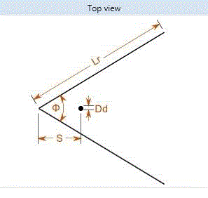
| ᴓ-Reflector angle Wr-Width of reflector
Lr-length of reflector Ld-length of dipole
S-spacing between reflector and dipole Dd-Width of dipole |
PSEUDO CODE |
| Step 1: Double click on the Icon, tool named Antenna Magus. |
| Step 2: When the folder opens, go to Home menu. Click on design tool bar by selecting the desired antenna. |
| Step 3: Set the operating frequency to 1GHz. |
| Step 4: click on design in ‘Design and Tweaks’ tool bar to design an antenna. |
| Step 5: All the parameters are set to desired value. |
| Step 6: Case1 is studied by varying spacing between dipole and corner reflector using the scroll and set to desired
value in order to increase the gain. |
| Step 7: Case2 is studied by varying the reflector angle using the scroll. |
| Step 8: Case3 is studied by varying the reflector length using the scroll |
| Step 9: In all the three cases, gain is observed. |
SIMULATION RESULTS |
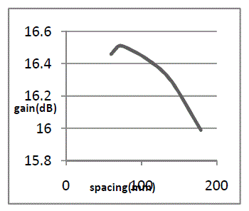
| Case1: Effect of spacing between dipole (source) and corner reflector on gain. |
| F- Frequency in GHz, B.W-Beam width, A-Angle in degree, G- Gain in dB. |
| In case1 all the parameters are kept constant and spacing between dipole and corner reflector is varied and gain is
observed and shown in below table1. |
| Table 1 describes that gain observed is maximum when the spacing between dipole and antenna ranges between
50mm to 70mm. |
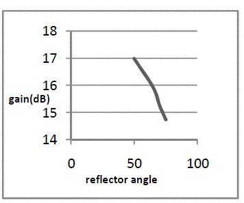
| Case2: Effect of reflector angle on gain. |
| In case2 all the parameters are kept constant and reflector angle is varied and gain is observed and shown in above
table2. |
| Table 2 describes gain observed is maximum when the reflector angle ranges between 50° to 65°. |
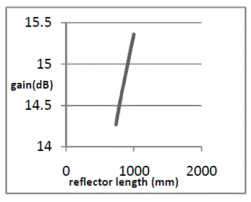
| Case3: Effect of reflector length on gain. |
| In case3 all the parameters are kept constant and reflector length is varied and gain is observed and shown in above
table3. |
| Table 3 describes that observed gain is maximum when length ranges between 0.8 to 1m. |
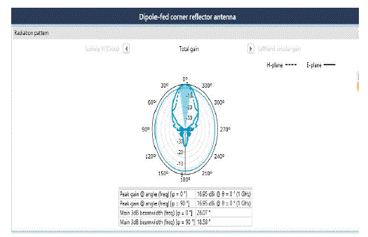
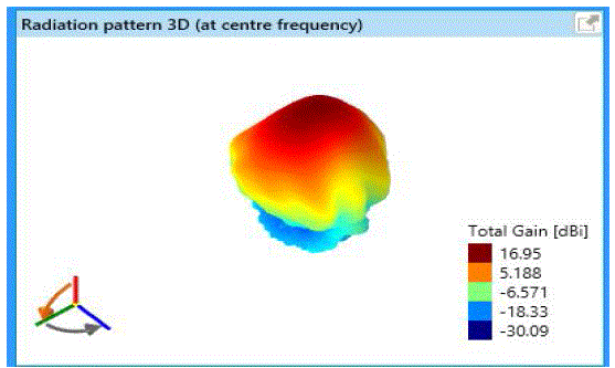
| Radiation patterns are obtained by varying spacing between dipole (source) and corner reflector and are shown in
Fig 3a &3b for 2D and 3D views respectively. |
| Fig 3a and fig 3b describes that the observed gain is 16.5dB for the variation of following parameters as follows: |
| Frequency: 1GHz, |
| Angle: 60°, |
| Reflector length: 1.47m, |
| Reflector width: 671.7mm, |
| Spacing between dipole and corner reflector: 70mm, |
| Dipole length: 139.7 mm, |
| Dipole width: 2.9mm, |
| Beam width at 0°: 27.16, |
| Beam width at 90°: 19.55. |
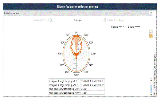
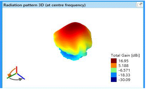
| Radiation patterns obtained by varying reflector angle are shown in below Fig 4a and Fig 4b for 2D and 3D views
respectively. |
| Fig 4a and 4b describes that the observed gain is 16.99dB for the variation of following parameters as follows: |
| Frequency: 1GHz, |
| Angle: 50°, |
| Reflector length: 1.47m, |
| Reflector width: 671.7mm, |
| Spacing between dipole and corner reflector: 80mm, |
| Dipole length: 139.7 mm, |
| Dipole width: 2.9mm, |
| Beam width at 0°: 26, |
| Beam width at 90°: 18.5. |
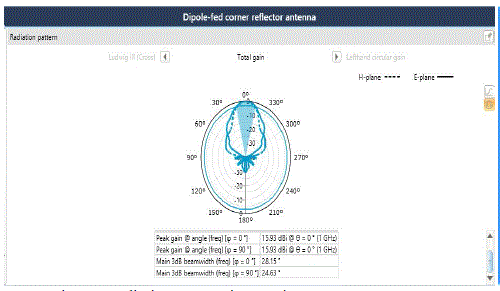
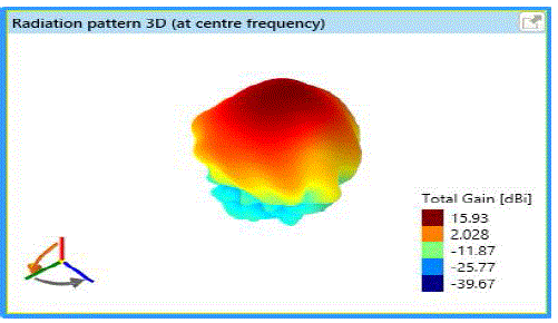
| Radiations patterns are obtained by varying reflector length are shown in fig 5a and fig 5b for 2D and 3D views
respectively. |
| Fig 5a and 5b describes that the observed gain is 15.36dB for the variation of following parameters as follows: |
| Frequency: 1GHz, |
| Angle: 50°, |
| Reflector length: 1m, |
| Reflector width: 671.7mm, |
| Spacing between dipole and corner reflector: 80mm, |
| Dipole length: 139.7 mm, |
| Dipole width: 2.9mm, |
| Beam width at 0°: 28.7, |
| Beam width at 90°: 22.09. |
Effects of antenna parameters on Gain |
| Fig 6a describes the variation of Gain with change in spacing between dipole (source) and corner reflector. From graph at spacing of 70mm,
Gain is maximum having 16.5dB.Fig 6b describes the variation of Gain with change in reflector angle. From graph, at 30° Gain is
maximum having16.99dB.Fig 6c describes the variation of Gain with change in reflector length. From graph, at 1000mm Gain is maximum
having 15.36dB. |
APPLICATIONS |
| 1. Corner reflectors can be used in TV system. |
| 2. For point to point communication, corner reflectors are more convenient. |
| 3. Corner reflectors are used in radio astronomy. |
| 4. Corner reflectors are used in Wi-Fi applications. |
CONCLUSION |
| The Corner reflector antenna is designed using Antenna Magus. Antenna is designed by varying parameters such as reflector angle,
Spacing between source and reflector and reflector length, Gain is observed for all the cases and can be concluded that antenna with spacing
70mm, reflector angle of 50° and reflector length of 1m gives gain of 16.5dB, 16.99dB and 15.36dB. |
ACKNOWLEDGEMENT |
| The authors wish to thank at the authorities of college BLDEA CET Bijapur, HOD E&C Department for facility extending to do present work. The authors are also grateful to the faculty Mrs. Daneshwari Hatti, Asst. Professor, Dept. of ECE for guiding to complete the work. The authors also would like to thank the unknown reviewers for their valuable comments which help in improving the paper. |
Tables at a glance |
|
|
Figures at a glance |
 |
 |
 |
 |
| Figure 1 |
Figure 2 |
Figure 3a |
Figure 3b |
 |
 |
 |
 |
| Figure 4a |
Figure 4b |
Figure 5a |
Figure 5b |
 |
 |
 |
| Figure 6a |
Figure 6b |
Figure 6c |
|
References |
- A.C. Wilson, ?Impedance of a corner reflector antenna as a function of diameter and length of the driven element?, JOURNAL OF RESEARCH of the National Bureau of Standards-D. Radio Propagation, Vol.64.D, No 2, March-April, 1960.
- Sebastian Mathew, Joe Jacob, V.P. Joseph, S. Bijukumar, U. Raveendranath and K.P. Mathew ?A New Corner Reflector Antenna with periodic strips sub reflectors?, Microwave and Optical technology letters, Vol.20, No 5, March 5, 1999.
- John D Krauss, Antennas and Wave Propagation, 4th ed.McGraw-Hill International edition, 2010.
- C. A. Balanis, Antenna Theory: Analysis and Design, 3rd ed., John Wiley India Pvt. Ltd, 2008.
- Prof K.Giridhar, Antennas and Propagation, 1st ed., Pooja Publications, Bangalore
|