ISSN ONLINE(2278-8875) PRINT (2320-3765)
ISSN ONLINE(2278-8875) PRINT (2320-3765)
R.Chidanandappa1, Dr.T.Ananthapamnabha2
|
| Related article at Pubmed, Scholar Google |
Visit for more related articles at International Journal of Advanced Research in Electrical, Electronics and Instrumentation Engineering
Current Source Inverter (CSI) fed induction motor drives finds application in high power medium voltage drives such as fan drives, where fast dynamic response is not needed because of the inherent four quadrant operation and reliability. Speed control of induction motors by Direct Torque Control -DTC method has more advantages compared to other methods. The most important Constant – Switching of DTC with PI control method based on constant switching frequency with modification of the inverter optimal switching table is presented. By using Direct torque control method the torque and speed response can be improved and thus improving the performance of the machine. The Matlab/Simulink software is used to model the CSI fed induction motor drive with DTC control and performance parameter are analysed and compared.
Keywords |
| current source converter , Direct torque control , space-vector modulation (SVM) |
I. INTRODUCTION |
| The direct torque control (DTC) is one of the actively researched control schemes of induction machines, that provides a very quick and precise torque response without the complex field-orientation block and the inner current regulation loop. In Direct Torque Control it is possible to control directly the stator flux and the torque by selecting the appropriate inverter state.. DTC is the latest AC motor control method, developed with the goal of combining the implementation of the V/f-based induction motor drives with the performance of those based on vector control [1-3]. It is not intended to vary amplitude and frequency of voltage supply or to emulate a DC motor, but to exploit the flux and torque producing capabilities of an induction motor when fed by an inverter .CSI permits easy power regeneration to the supply network under the breaking conditions, what is favorable in large power induction motor drives. In a direct torque controlled induction motor drive supplied by current source inverter it is possible to control directly the modulus of the rotor flux-linkage space vector through the rectifier voltage, and the electromagnetic torque by the supply frequency of the CSI[4]. In this paper the solution based on a stator flux vector control (SFVC) scheme has been proposed . This scheme may be considered as a development of the basic DTC scheme with the aim of improving the drive performance. |
II. CONSTANT SWITCHING DIRECT TORQUE CONTROL |
| In DTC schemes, the presence of hysteresis controllers for flux and torque determines variable-switching-frequency operation for the inverter. Furthermore, using DTC schemes an fast torque response over a wide speed range can be achieved only using different switching tables at low and high speed. The problem of variable switching frequency can be overcome by different methods [5]. Controllers based on direct torque control do not require a complex coordinate transform. The decoupling of the nonlinear ac motor structure is obtained by the use of on-off control, which can be related to the on-off operation of the inverter power switches. Similarly to direct vector control, the flux and the torque are either measured or estimated and used as feedback signals for the controller. However, as opposed to vector control, the states of the power switches are determined directly by the measured and the reference torque and flux signals. This is achieved by means of a switching table, the inputs of which are the torque error, the stator flux error and the stator flux angle quantized into six sections. The outputs of the switching table are the settings for the switching devices of the inverter. In proposed stator flux vector control (SFVC), the input commands are the torque and the rotor flux, whereas the control variables are the stator flux components. The principle of operation is based on driving the stator flux vector toward the corresponding reference vector defined by the input commands. This action is carried out by the space-vector modulation (SVM) technique, which applies a suitable voltage vector to the machine in order to compensate the stator flux vector error. In this way it is possible to operate the induction motor drive with a constant switching frequency. |
| The proposed DTC-CSI drive shown in Fig.1. the inputs are rotor flux and torque but the stator flux angle α s is a control |
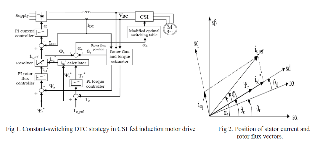 |
| Identical result would be obtained when phase angle Φs between d-q current references and rotor flux vector angle θe = arctan (Ψrβ/Ψrα) are summed and resulting angle αs is then used to determine sector of 60 degrees where resides rotor flux vector. In that way, phase angle Φs acts as a torque control command, since when reference torque is changed, isq* is momentary changed . Fig. 2. represent phasor diagram with reference current vector, rotor flux vector and corresponding angles. |
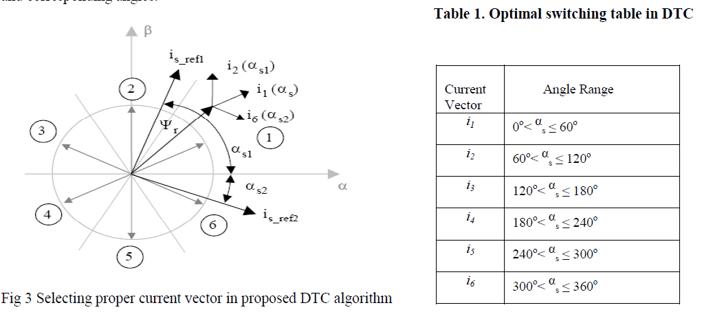 |
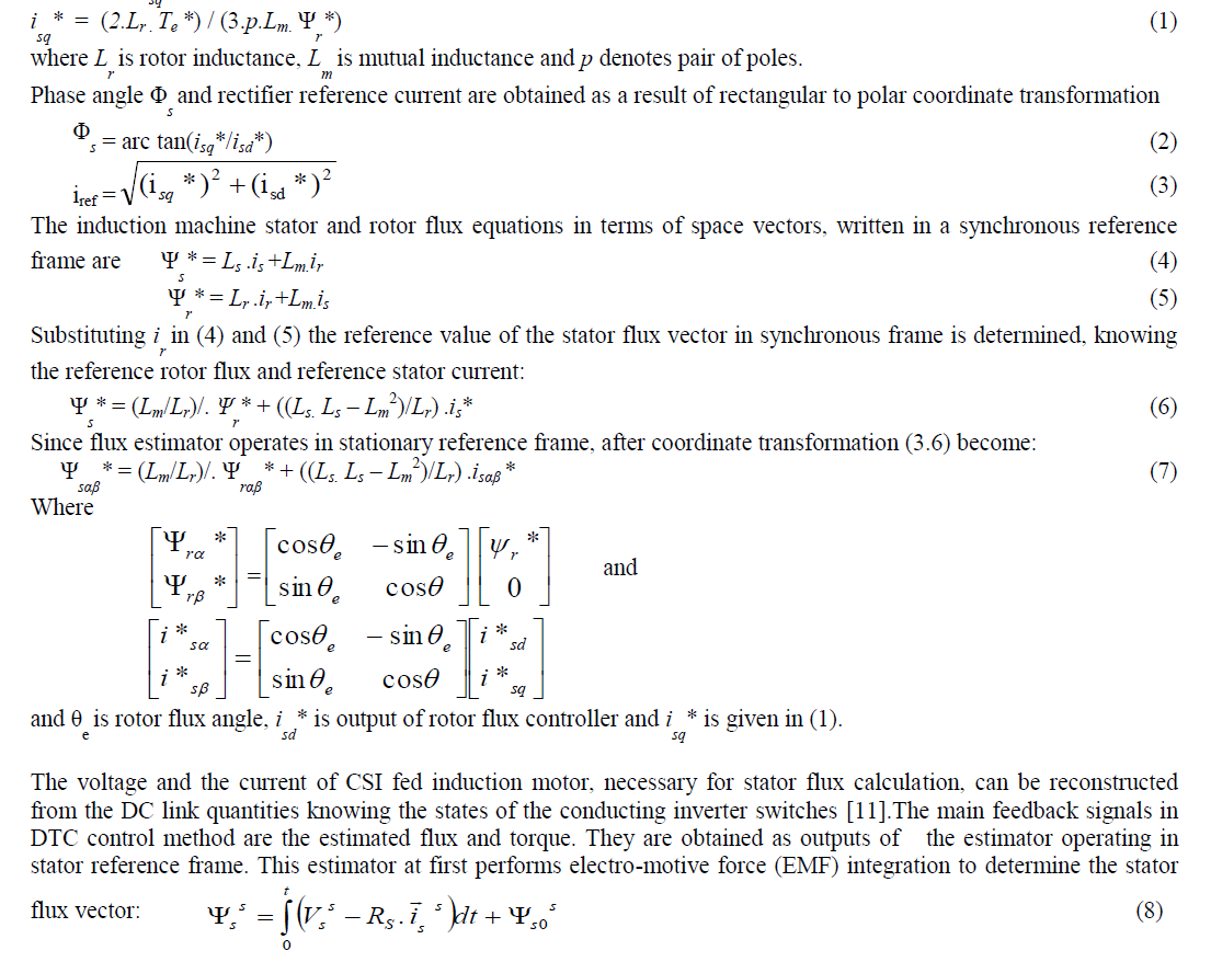
| Phase angle Φ s “moves” stator current vector i s in direction determined by the sign of torque reference and its value accelerate or decelerate flux vector movement according to the value of the reference torque (Fig.3). This modification implies somewhere different switching table for activating inverter switches, as shown in Table 1, where α s is angle between reference α-axis and reference current vector i s . That angle determines which current vector should be chosen: i 2 for torque increase, i 6 for torque decrease or i 1 for keeping torque at the current value. |
III. MEASURING AND ESTIMATION |
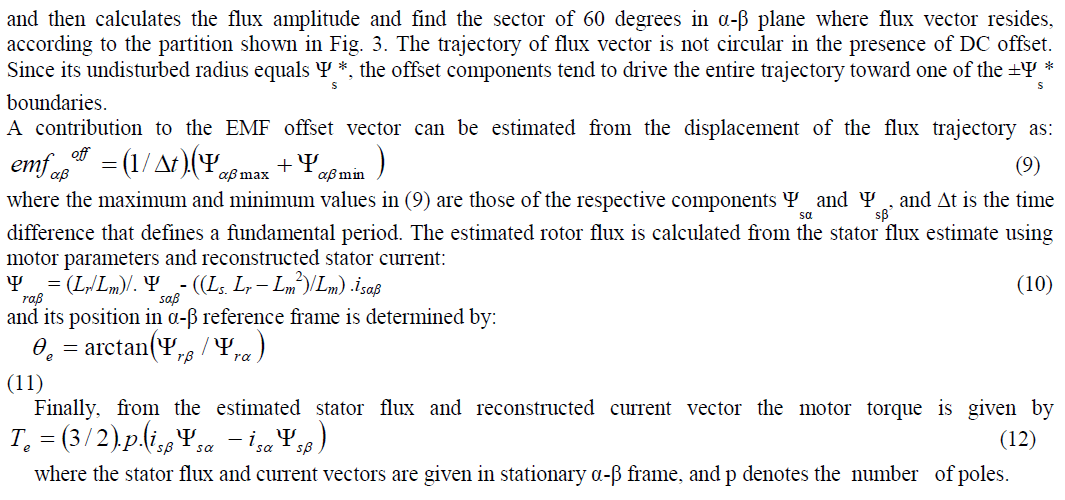
| The stator flux value, needed for DTC control loop, is not convenient to measure directly. Instead of that, the motor flux estimation is done. In the voltage-based estimation method, the motor flux can be obtained by integrating its back electromotive force (EMF). The EMF is calculated from the motor voltage and current and the only motor parameter required is the stator winding resistance. The input variables of the proposed prototype are motor torque T e * and rotor flux amplitude Ψ r *. Control variables are current components in synchronous reference frame i sd * and i sq * and phase angle between them (Φ s ). D-axis component i sd * is determined as the output of the PI rotor flux controller, while q-axis component i sq * is calculated from the input variables and motor. |
 |
 |
IV. MODELING OF CURRENT SOURCE INVERTER |
| In current source inverter (CSI) , the input behaves as a current source, the output current is maintained constant irrespective of the load on the inverter and the output voltage is forced to change. The circuit diagram of three phase current source inverter is shown in Fig 4.A three phase output can be obtained from a configuration of six switches Two types of control signals can be applied to the switch: 1800 and 1200 conduction. The 1800 conduction has better utilization of switches and is the preferred method. |
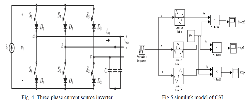 |
| Each switch conducts for 180° . When switch S1 is ON then terminal a is connected to the positive terminal of the DC input voltage. When switch S4 is ON terminal a is brought to the negative terminal of the DC source. The table 2. shows six valid switching states . |
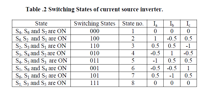 |
| The current source inverter converts direct current into alternating current. Fig .5 shows the simulink model of CSI. The look up table is designed to suit the switching state of current source inverter given in Table 2. |
V. RESULTS AND DISCUSSIONS |
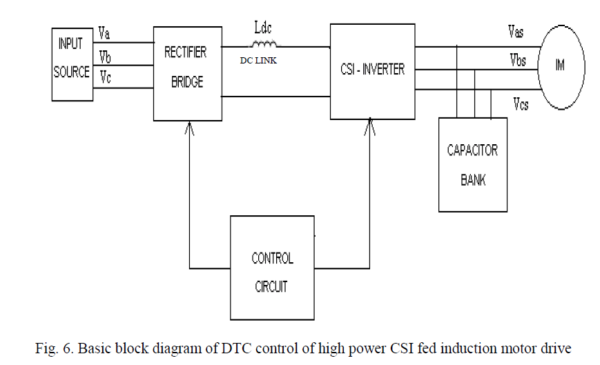
| The block diagram of proposed work is given in fig 6 . It consists of rectifier bridge, current source inverter(CSI), Induction motor , control circuit and capacitor bank. Rectifier bridge converts the AC input from source to DC. Current source inverter converts the DC input to AC output which consists of harmonics. The output of CSI is filtered using capacitor and fed to the induction motor. The control circuit block simulates the Direct torque control algorithm . |
 |
| The parameter values used in modeling are Induction motor of 400V, 3.78KW, 50HZ ,Rs = Rr= 1.5313 Ω, Ls = Lr =0.2194 H,L0 = 0.21 H, Poles = 4 , Flux rated = 1.555 wb, J = 0.25 Kg_m2 , B = 0.0248 Kg_ m2/sec, Ldc= 42mH,Cdc= 11μF. |
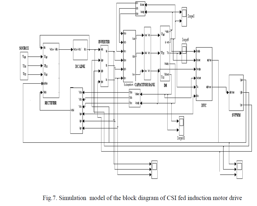
| Each block is modeled in Matlab/ simulink software, the simulation model of the block diagram shown in fig7. The Simulation carried out for fallowing cases ; |
| 1. CSI fed induction motor drive without DTC control |
| 2. CSI fed induction motor drive with DTC control |
 |
 |
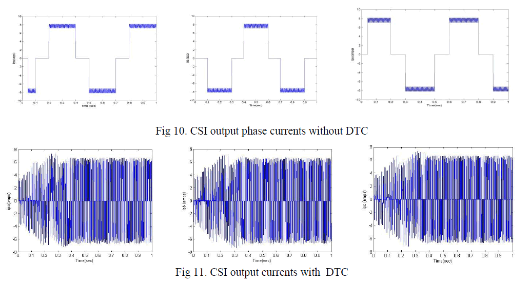 |
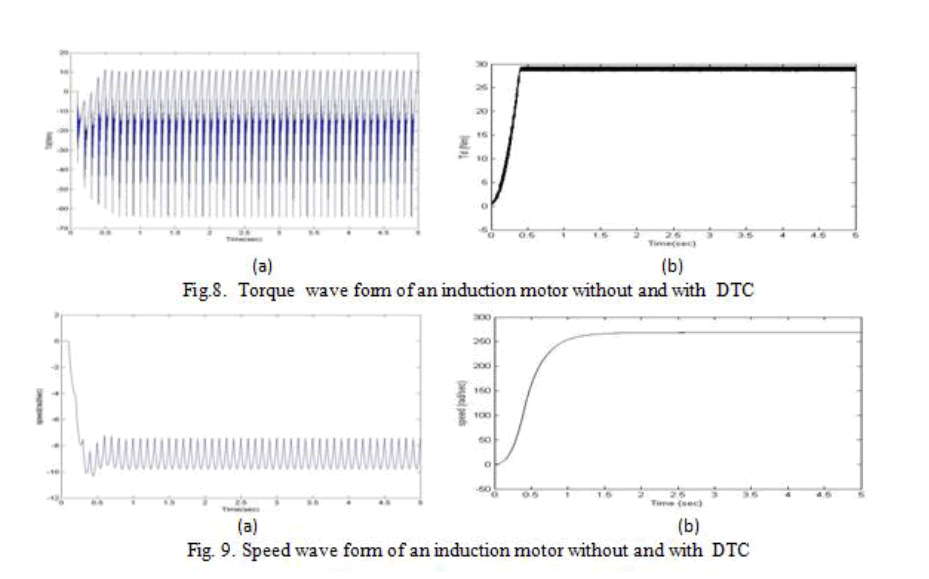
| From the simulation results shown in fig 8 (a) an 9(a) without DTC control, the torque and speed response is slow and consists of ripple due to harmonics produced by CSI. The induction motor torque and speed response is fast with Direct Torque control method and stability is attained quickly at 0.4 sec as seen from fig 8(b) and fig. 9(b). Without DTC , CSI output current in all phases contains more ripple shown in fig .10 and ripples are reduced with DTC shown in fig 11. |
 |
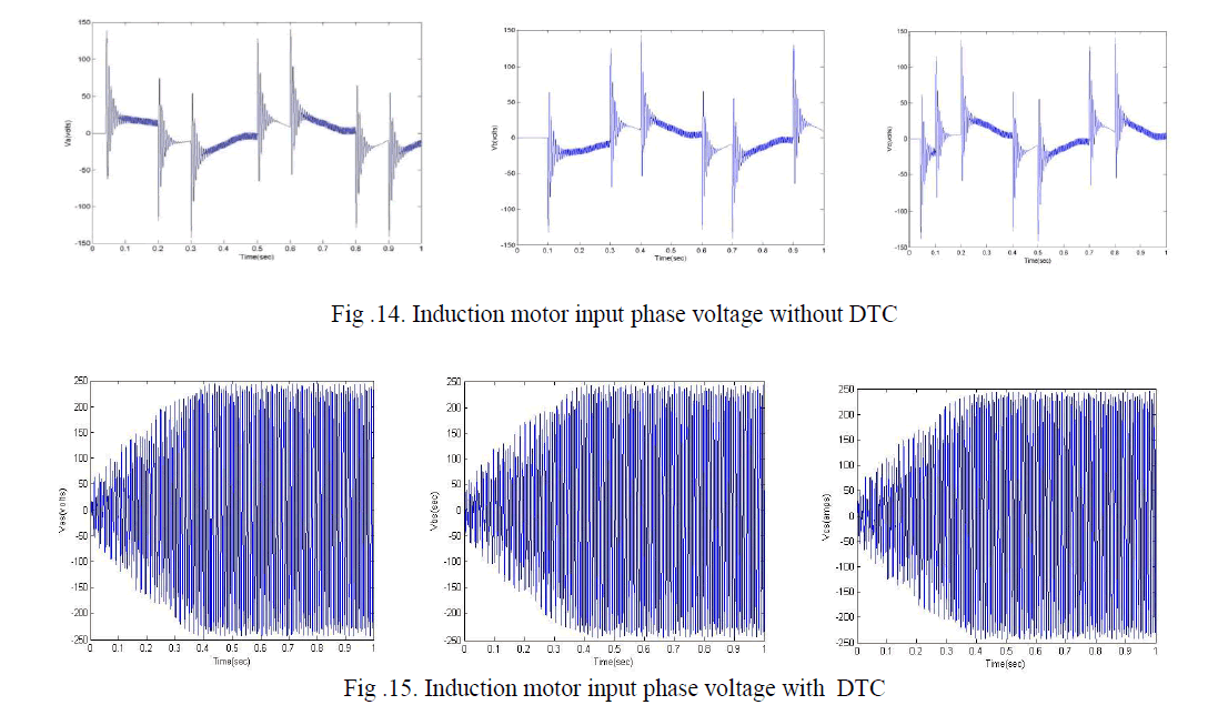 |
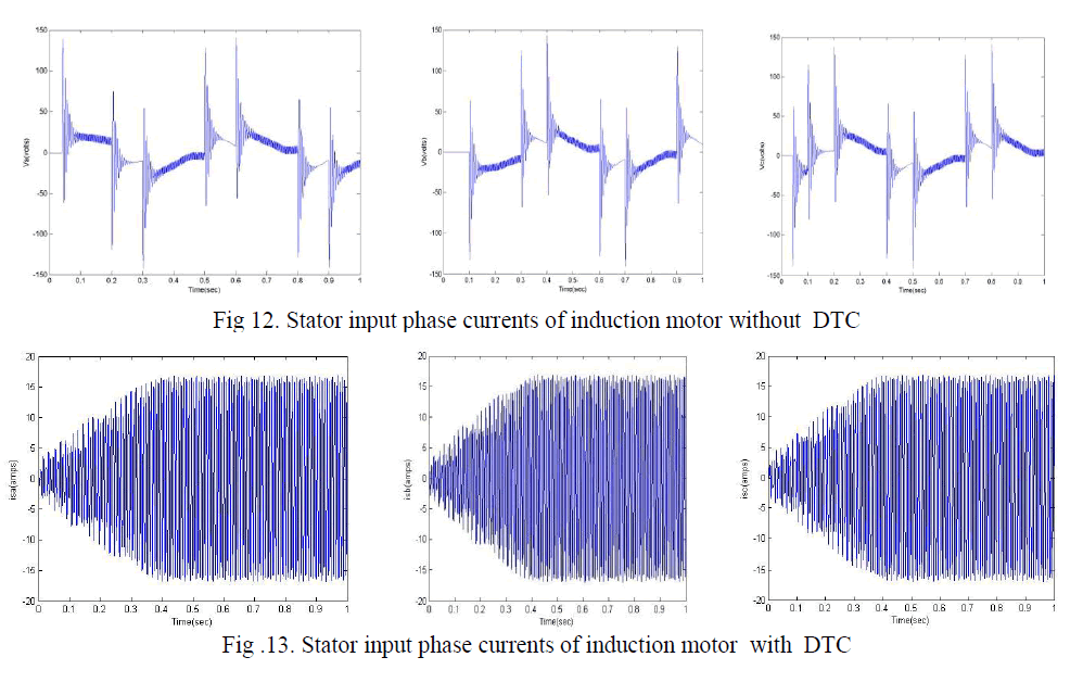
| The stator input currents and input voltages obtained without DTC control , are not reached to nominal values and contains harmonics shown in fig 12 and fig 14 respectively. From the in fig.13 and fig.15 it is seen that ,with DTC control induction motor phase currents and voltages reached to desired operating value and approximately sinusoidal in nature . |
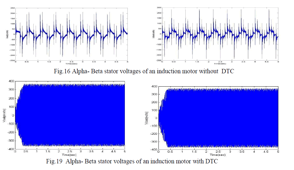 |
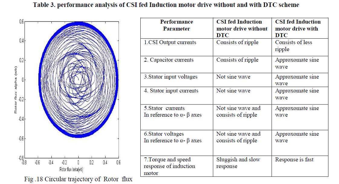
| The Stator currents and voltages in alpha-beta reference frame are almost sinusoidal and stator current attains stability fast as seen from the fig16 and fig 17 respectively. DTC indirectly controls stator current and voltage , reducing Vsalpa, Vsbeta to 375V as seen from fig 17. Depending on which sector does the rotor flux falls, particular inverter gate pulses are selected .The rotor flux estimated is sinusoidal and it has circular trajectory as seen from fig 18. From the simulation of the two cases , performance parameters of drive with and without DTC scheme are compared and tabulated in table 3. |
 |
VI. CONCLUSIONS |
| Induction motor torque response can be controlled effectively by Direct Torque control method. The inverter current is controlled by SVPWM stratergy. This method eliminates the co-ordinate transformation done in vector control method which consumes more computing time. The torque and speed response time is reduced. With DTC Power loss in current source inverter is reduced. Stator and rotor flux estimated are sinusoidal in nature and it has a circular trajectory. The stator currents and voltages is indirectly controlled by DTC and are approximately sinusoidal. |
References |
|