Keywords
|
| Error control coding, Bit error probability, Parity code, Hamming code, Coding/Decoding circuits, improvement ratio. |
INTRODUCTION
|
| Communication is fundamental to human existence and nothing is more indicative of this need than the phenomenal growth of The Internet and the Worldwide Web. For any form of communication we need a medium or channel for the propagation of information. Most common modern medium is the telephone channel which traditionally carried audio signals in analogue form. With the advent of computers and digital techniques, most information traffic is now digital and this has opened the need for research into a new area of difficult and interesting engineering problems. The number of applications of digital traffic is limited only by the imagination, but we can readily divide it into two classes. The first class can tolerate a relatively high error (from 10-3 to 10-4) and examples of this class are digitised voice and video. The occasional incorrectness of the data does in not affect the quality of communications significantly. On the other hand, the 2nd class of traffic ideally requires perfect integrity of data (in practice an error rate of about 10-9), and an example is computer information. With the technique of coding it is possible, at the expense of complexity, to vastly improve on the error rate without sacrificing the data rate, increasing the bandwidth or increasing the power. Error correcting codes are well known techniques for improving BER performance in digital communication systems and are particularly important in wireless information networks. Such codes are useful in minimizing transmitter power levels as well as antenna size (and hence reduce hardware costs) to maintain a satisfactory BER. Error detection and correction is usually implemented by including a forward error correction (FEC) encoder in the transmitter and decoder in the receiver. Error control is usually obtained by adding redundancy to the message signal to be transmitted and this implies increased transmission bandwidth. Since FEC adds complexity to the system design tradeoffs have to be made between RF transmission bandwidth and system complexity to maintain the desired BER performance. |
| Forward error correction codes which can correct burst errors and that are in use today are Parity code, Hamming code and Reed Solomon code[5]. In evaluating the coding schemes the reliability of coder & decoder circuits is usually assumed to be non faulty and probability of undetected error is calculated with and without coding.But the coding and decoding circuits failure also leads to undetected errors and then IC circuit reliability is an important component of undetected error rate. This paper gives the study of the effect of circuit failures for the three coding schemes taking into consideration different message lengths and Baud rates. |
TYPES OF CODING TECHNIQUES
|
| A. Parity Code |
| A parity bit is an extra 0 or 1 bit attached to a code group at transmission. In the even parity method the value of the bit is chosen so that the total number of 1s in the code group, including the parity bit, is an even number. With odd parity the parity bit is chosen so that the total number of 1s, including the parity bit, is odd. Thus if at the receiver the number of 1s in a code group does not give the required parity, the receiver will know that there is an error and can request that the code group be retransmitted. An extension of the parity check is the checksum in which a block of code may be checked by sending a series of bits representing their binary sum. Parity and checksums can only detect single errors in blocks of code, double errors go undetected. Also, the error is not located so that correction by the receiver can be made.In this section how parity bit coding decreases probability of error is analysed. |
| B. Hamming Code |
| Hamming codes are the first class of linear codes devised for error correction [6].These codes and their variations have been widely used for error correcting in digital communication. |
| For any positive integer m≥3, there exists a hamming code with the following parameters: |
| Code length : n= 2m-1 |
| Number of information symbols: k= 2m-m-1 |
| Number of parity check symbols : n-k = m |
| Error correcting capability: t=1(dmin=3) |
| Hamming codes are most widely used linear block codes. A Hamming code is generally specified as (2m-1, 2m-m-1).The size of the block is equal to 2m-1. If |
| d = code (hamming) distance |
| D = no. of errors which a code can detect |
| C = no. of errors which a code can correct |
| n = total no.of bits in coded word |
| m = total no of message or information bits |
| c = no. of check or parity bits |
| where d, D, C,n, m and c are all integers ≥ 0, and d ≥ D+C+1 (1) |
| One can develop the entire class of Hamming codes by solving Eq (1) remembering that D ≥ C & d, D & C are integers ≥ 0. |
| C. Reed Solomon Codes |
| An RS code is a cyclic symbol error-correcting code. An RS codeword will consist of information or message symbols, together with P parity or check symbols. The word length is N=I+P.The symbols in an RS codeword are usually not binary, i.e., each symbol is represented by more than one bit. In fact, a favorite choice is to use 8-bit symbols. This is related to the fact that most computers have word length of 8 bits or multiples of 8 bits. In order to be able to correct „tâÃâ¬ÃŸ symbol errors, the minimum distance of the code words „DâÃâ¬ÃŸ is given by D=2t+1.Code length n =q −1 |
| Number of parity check elements, |
| (n-k) = 2t (for n-k even) |
| (n-k) = 2t+1 (for n-k odd) |
| Minimum distance dmin = 2t +1 |
| Error-correction capability t element errors per code vector |
MEASURE OF PERFORMANCE OF A CODE
|
| The probability of detecting errors ie., success of a code is denoted by PâÃâ¬ÃŸue and the probability of not detecting error , Pue is a measure of failure. These probabilities can be simply calculated using the binomial distribution. The probability of r failures in n occurrences with failure probability q is given by the binomial probability B(r : n, q) given by, |
| B (r : 9, q) = ïÿýïÿýïÿýïÿý r qr (1-q)r (2) |
| A. Parity Code |
| Let us consider the addition of a ninth parity bit to an 8 bit message byte. If there are one, three, five, seven or nine errors in the received word the parity is violated and the checking circuit will detect an error[1]. The probability of an undetected error. P'ue is the probability of two, four, six or eight errors, since these combinations do not violate the parity check. The probability of an undetected error with parity bit coding with 2 errors becomes |
| PâÃâ¬ÃŸ ue = B (2 : 9, q)=36q2 (1-q)7 (3) |
 |
EFFECT OF CIRCUIT FAILURE ON PERFORMANCE OF A CODE
|
| The analysis of Sec III was performed assuming the coding and decoding circuits as fault free. In this section, we analyse how the faulty circuits effects the performance of the above mentioned codes under the same conditions of different message lengths and baud rates. As per simple model for IC reliability with a series of periodically updated failure rate manuals known as MIL-HDBK-2 17, A, B, C,... model assumes the failure rate of an integrated circuit is proportional to the square root of the number of gates, g in the equivalent logic model [2]. Thus the failure rate / million hrs. is given as λ = C(g)1/2 , where C was computed from 1985 IC failure rate data as 0.004. This model is used to estimate the failure rate and subsequently the reliability of an IC generator & checker. In formulating the reliability model for a coder-decoder scheme of the coded word two modes of failure is considered. A) where the coder and decoder do not fail but the number of bit errors is an undetectable even number equal to two or more and B) where the coder or decoder chip fails so it does not detect errors. chip failure modes which sometimes give correct results is ignored[3]. The probability of undetected error with the coding scheme is given by: |
| PâÃâ¬ÃŸ ue = P (A + B) = P (A) + P(B) (11) |
| Normally P (A) and P (B) are quoted in different units as failures/hr and failures/byte respectively. To ensure that failures/hr and failures/byte are properly treated we write Eq (11) as |
| PâÃâ¬ÃŸue = P [no coder or decoder failure during one byte transmission] * [two or more errors] + P [coder or decoder failure during one byte transmission] |
| If we assume a constant failure rate, λb for the coder and decoder the reliability of a coder-decoder pair is e-2 λ b t and the probability of coder or decoder failure is (1 - e-2 λ b t). |
| A. Parity bit generator/checker |
| The standard circuit for a parity bit generator checker is a "tree structure" of n exclusive or gates. However, it is more realistic to assume that we are using a commercial circuit device. The SN74180, a 9-bit odd/even parity generator/checker [9]. This SN74180 chip is designed for generating a parity bit from eight message bits. Considering the logic diagram for an 8+1 parity code, we find five EX-NOR and twoEX-OR gates and the16-bit even/odd parity generator/checker 74HC/HCT7080 logic diagram of 16+1 parity code has 15 EXNOR, 01 EXOR and 17 NOT gates[4]. In the equivalent gate model for the SN74180 there are: five EXNOR, two EXOR, one NOT, four AND, and two NOR gates. Assuming the two EXOR and five EXNOR gates use about 1.5 times as many transistors to realize their function as the other gates, we will consider the Seven of them equivalent to 10.5 gates. Adding the other gates, we have 17.5 equivalent gates and λb =0.004(17.5)1/2 failures per million hours = 1.67 x 10⁻⁸ failures per hour. The probability of two or more errors per hour is given by Eq. (3). Thus Eq.(12) becomes |
 |
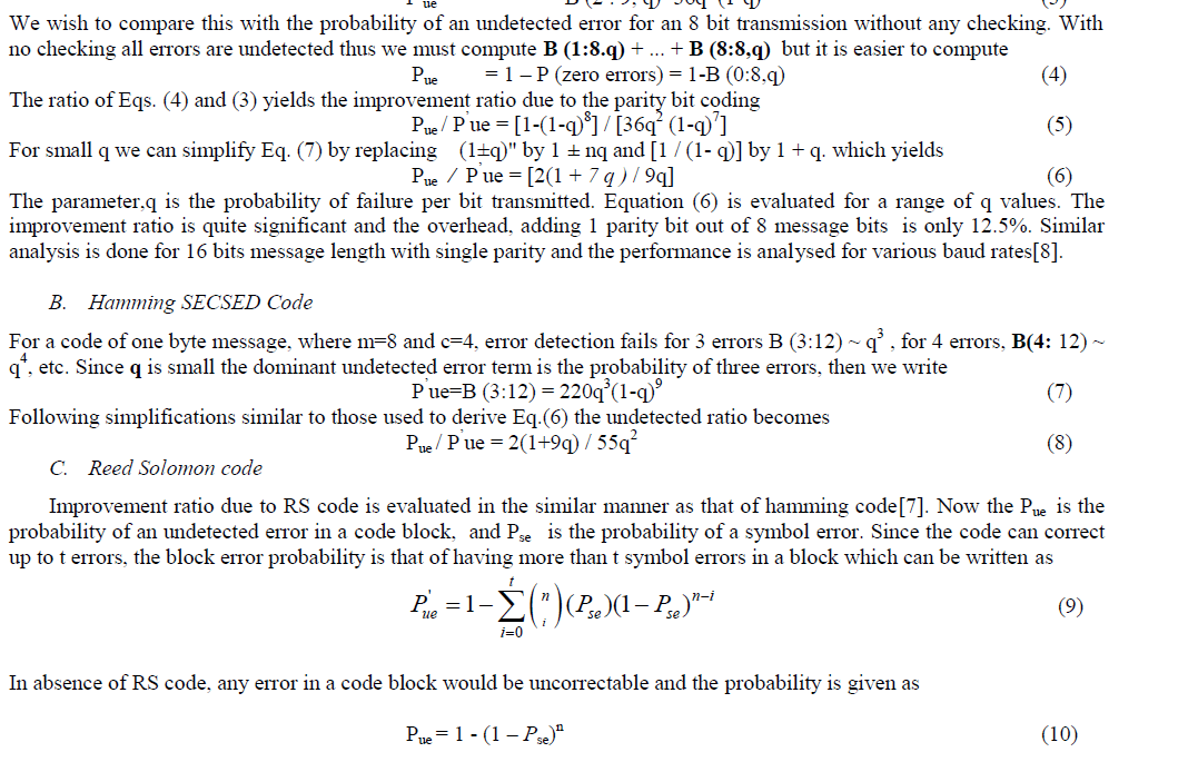
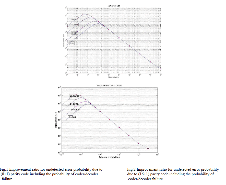
| The ratio of Eq. (4) to Eq. (13) is plotted in Fig.1 for typical modem bit rates B = 300, 1200, 9600, 56000 [8]. Note that the chip failure rate is insignificant for q = 10-4, 10-5 and 10-6 & however it does make a difference for q = 10-7 and 10-8. If the bit rate B is infinite, the effect of chip failures disappears. Similarly if evaluated for 16 bit parity generator / checker the improvement ratio will be as shown in Fig2. From Fig.2 it can be observed that circuit failure effect dominates for q<10-8 and is insignificant for q > 10-4, 10-5,10-6 and 10-7 . Thus as the message length increases the probability of error increases i.e., circuit failure rate is insignificant for higher values of q. |
 |
| B. Hamming coder/decoder |
| The reliability of the generator checker circuitry using the IC failure rate model , λb= 0.004(g)1/2 for hamming coder /decoder is calculated. Thus, the failure rate for the coder and decoder is λb = 13.58*10-8. Using Eq.(7) an expression similar to Eq.(13) is as shown below. |
 |
| Where λ= 16.56*10-8 failures/hr |
| t= 12/3600B |
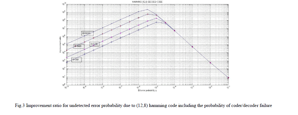
| the improvement ratio is calculated by dividing B (0: 12, q) by Eq. (15), and the ratio is plotted in Fig. 3. The ratios of the SECSED code (Fig. 3) are much larger than those of the parity bit code in shown in Fig.1 & Fig.2. Figure 3 reveals that for data bit rates, B below 56 kbps and bit error rates, q<10-5 Forward Error Correction coder/decoder chip failures can be significant. |
 |
 |
| C. RS coder/decoder |
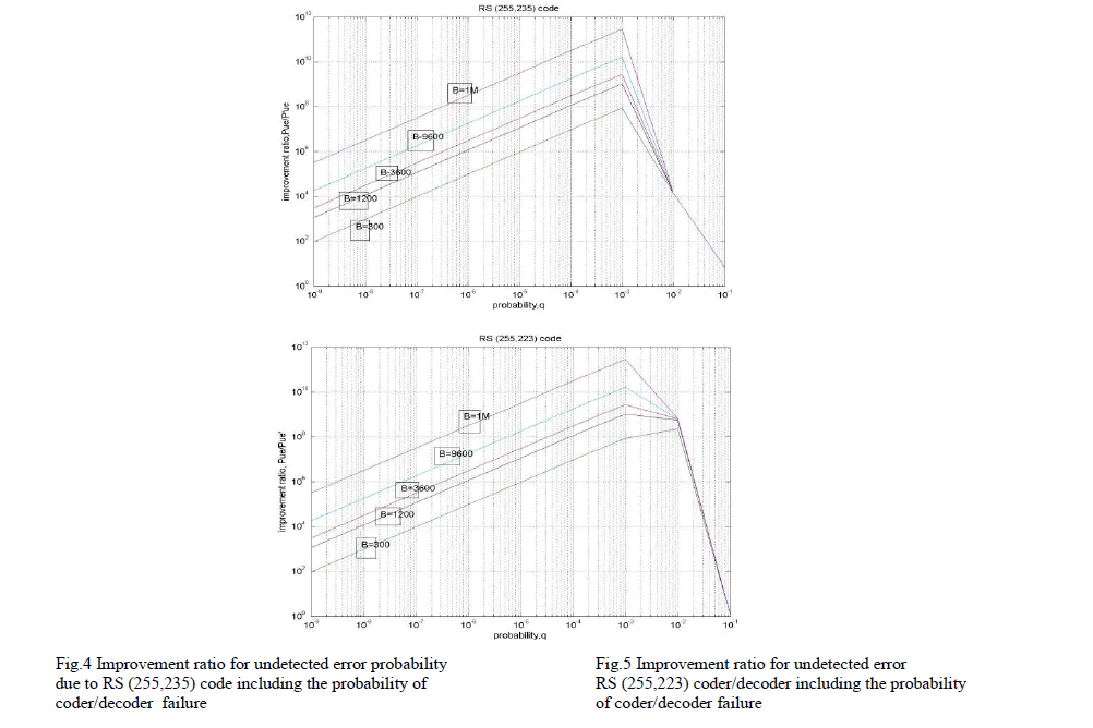
| Eq. 12 is used to evaluate the effect of RS coder/ decoder failures. However instead of computing per byte of transmission, per block of transmission is calculated. Thus, by Eq.13, |
 |
COMPARISON OF 3 CODES
|
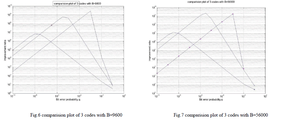
| Based on reliability probabilistic models of the (8+1) parity code, (12, 8) SECSED Hamming code, and (255,235) Reed Solomon code, we may get the following comparison curves as shown in Fig.6. using Baud rate of 9600 . Comparison plot of (16+1) parity code, (12, 8) SECSED Hamming code and RS (255,239) code is shown in fig 7 with a baud rate of 56000. From Fig.6 & Fig.7, it is observed that, |
| for q <10-8 parity code is better than Hamming. q <10-7 parity code is better than RS code. q<10-5 Hamming code is better than RS code |
CONCLUSIONS
|
| This paper explained that under certain circumstances [e.g., low bit error rate and low data transmission rates (bits/sec), variable message bits the chip failure probabilities can actually dominate and eliminate the gains achieved with coding. Because the Hamming SECSED code result in lower values for undetected errors than the parity bit code, the effect of chip failures is even more pronounced. Of course the coding is still a big improvement, however, not as much as one would predict. In fact, by comparing Figs. 1 and 3 we see that for B = 300, the parity bit scheme is superior to the SECSED scheme for values of q less than about 2 x 10⁻⁷ and for B = 1200, the parity bit scheme is superior to the SECSED scheme for values of q less than about 10-7.Not only that as the message length increased the probability of detecting error is decreased. This can be observed by |
 |
| comparing fig 1 & fig 2. Thus, the general conclusion is that for more complex error detection schemes one should evaluate the effects of generator and checker failures with variable message length, since these may be considerably important for small values of q. |
References
|
- Military Handbook, ”Reliability prediction of Electronic Equipment”: MIL-HDBK-217F.
- Texas Instruments TTL Logic Data Book. 1988. pp. 2-10 .
- Wakerley, J.F.: Digital Design of Principles and Practice, Prentice-Hall, 1990. .
- Shooman, M. L.: Probabilistic Reliability: An Engineering Approach, First Ed., McGraw-Hill Book, Co.,New York, 1983, Second Ed, KreigerPublications,Melbome FL, 1990.
- Andrea Goldsmith,”Wireless Communications”, Cambridge University Press, 2005.
- Jorge castineiramoreire& Patrick Guy Farrell, “essentials of error control coding”, John Wiley & Sons Ltd, 2006
- Tood K Moon,”Error Correction Coding-Mathematical Methods & Algorithms”, John Wiley & Sons Inc Publication, 2005. 74HC/HCT7080 16- bit even/odd parity generator checker, Philips Semiconductor.
|