Keywords
|
| Diversity, Fading channels, Combining Techniques, Wireless Communications, MIMO, STC, spatial multiplexing, Capacity, Amplify and Forward, Decode and Forward, Cooperation |
CHALLENGES IN WIRELESS SIGNAL TRANSMISSION
|
| Wireless Communication has made a tremendous impact on the lifestyle of a human being. Wireless Network provides high speed mobility for voice as well as data traffic from variety of sources. The fundamental phenomenon which makes transmission unreliable is time varying fading [1]. The phenomenon is described as the constructive and / or destructive interference between signals arriving at the same antenna via different paths, and hence with different delays and phases, resulting in random fluctuations of the signal strength at the receiver. When destructive interference occurs, the signal power can be significantly reduced and the phenomenon is called as fading. Deep fades that may occur at particular time or frequency or in space result in severe degradation of the quality of the signal at the receiver making it sometimes impossible to decode or detect. Multipath fading arises due to the non-coherent combination of signals arriving at the receiver antenna. |
| There are many kind of interference in real wireless communications. One important cause is the multi-path propagation. In analog type of TV broadcasting, ghost phenomena are observed due to multipath effects. The delayed signal is generated by the multi-path. This causes the overlapping between the current symbol and the previous symbol. This overlap causes the inter symbol interference (ISI) which destroys the sub-carrier orthogonality in Orthogonal Frequency Division Multiplexing (OFDM) system. The multipath fading can often be relatively deep, i.e. the signals fade away completely, whereas at other times the fading may not cause the signal to fall below a certain useable strength [2]. |
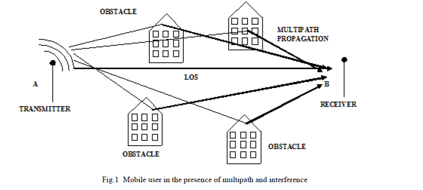
| Interference is caused by deep-fades that occur at a particular point in space, or at a particular time or frequency, and results in severe degradation of the quality of signals at the receiver making it impossible to detect or decode. Several mathematical models have been developed to describe such channels. The model takes into account the phenomenon of multipath fading and correlation between sub-channels. Common models employ Rayleigh, Ricean and Nakagami-m distributions to approximate actual channel conditions [3]. The performance of the systems (in terms of error rate) can be severely degraded by fading. Communication through these channels is difficult and special techniques may be required to achieve satisfactory performance [4]. Figure 1 shows the concept of interference caused by reflection of signals. |
 |
| A. Causes of Fading |
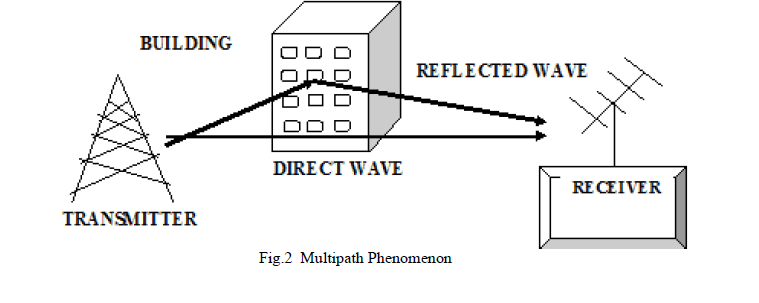
| The multipath effect is the main cause of fading and may be due to reflection of satellite signals (radio waves) from objects. It was the same effect that caused ghost images on television when antennas on the roof were still more common instead of today satellite dishes. In any terrestrial radio communications system, the signal will reach the receiver not only via the direct path, but also as a result of reflections from objects such as buildings, hills, ground, water, etc that are adjacent to the main path. The overall signal at the radio receiver is a summation of the variety of signals being received [5]. As they all have different path lengths and hence different phases, signals will add or subtract depending upon their relative phases. Figure 2 depicts the multipath echo formation from an actual target. The causes of fading are mainly reflection, diffraction, scattering and Doppler shift. |
| 1) Reflection |
| This occurs when waves impinges upon an obstruction that is much larger in size compared to the wavelength ïÿýïÿý of the signal. Examples are reflections from earth and buildings. These reflections may interfere with the original signal constructively or destructively. |
| 2) Diffraction |
| This occurs when the radio path between sender and receiver is obstructed by an impenetrable body and by a surface with sharp irregularities (edges). This details how radio signals can travel urban and rural environments without a lineof- sight (LOS) path. |
| 3) Scattering |
| This occurs when the radio channel contains objects whose sizes are on the order of the wavelength or less of the propagating wave and also when the numbers of obstacles are quite large. They are produced even by small objects, surface roughness and other irregularities on the channel. It follows same principles of diffraction. It causes the transmitter energy to be radiated in many directions. Examples are lamp posts and street signs that may cause scattering. |
 |
STATISTIACL MODEL FOR FADING CHANNELS
|
| To understand wireless communications, it is necessary to explore what happens to the signal as it travels from the transmitter to the receiver. As cited earlier, one of the important aspects of this path between the transmitter and receiver is the occurrence of fading. Many models for the probability distribution function (PDF) of the signal amplitude exposed to mobile fading are there to explain such fading phenomena. Out of these models Rayleigh, Ricean and Nakagami fading models are most widely used because of both academic and practical application points of view. |
| A. Rayleigh Fading Channel: |
| Rayleigh fading describes the received signal envelope distribution where all the components are non-line of sight [6],[7]. The basic model of Rayleigh fading assumes a received multipath signal to consist of a (theoretically infinitely) large number of reflected waves with independent and identically distributed (i.i.d) in phase and quadrature amplitudes [8]. The mobile or indoor radio channel is characterized by multipath reception. The signal offered to the receiver contains not only a direct line-of-sight (LOS) radio wave, but also a large number of reflected radio waves. In urban centers, the LOS is often blocked by obstacles, and a collection of differently delayed waves is received by a mobile antenna. These reflected waves interfere with the direct wave, which causes significant degradation of the performance of the link. Additionally, if the antenna moves, the channel varies with location and time, because the relative phases of the reflected waves change. This leads to fading: time variations of the received amplitude and phase. In a non-fading (thus fixed) radio channel the Bit Error Rate (BER) decreases rapidly when the signal-to-noise (more specifically, signal-to-interference) ratio is increased. This phenomenon remains present, even if the (average) signal-to-noise ratio is large. So the BER only improves very slowly, and with a fixed slope, if plotted on a log-log scale. A wireless system has to be designed in such way that the adverse effect of multipath fading is minimized [8]. |
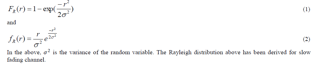
| The random variable R following Rayleigh fading has the cumulative distribution function (CDF) ïÿýïÿýïÿýïÿý(ïÿýïÿý) and probability density function (PDF) fïÿýïÿý(ïÿýïÿý) given by, |
 |
| B. Ricean Fading Channel |
| The model behind Ricean fading is similar to that for Rayleigh fading, except that in Ricean fading a strong dominant LOS component is present. A refined Ricean model also considers the following: |
| ïÃâ÷ The dominant wave can be a phasor sum of two or more dominant signals, e.g. the line-of-sight, plus a ground reflection. This combined signal is then mostly treated as a deterministic (fully predictable) process, and |
| ïÃâ÷ The dominant wave can also be subject to shadow attenuation. This is a popular assumption in the modeling of satellite channels. |
| Besides the dominant component, the mobile antenna receives a large number of reflected and scattered waves as well. |
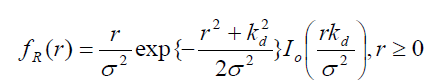
| As stated, the Ricean distribution results when, in addition to the multipath components, there exists a direct path between the transmitter and the receiver. The envelope in this case has a Ricean density function f (r) R given by [9] |
 (3) (3) |
| where (.) o I is the th 0 order modified Bessel function of the first kind, constant d k determines the strength of the direct component. The cumulative distribution of the Ricean random variable F (r) R is given as |
 |
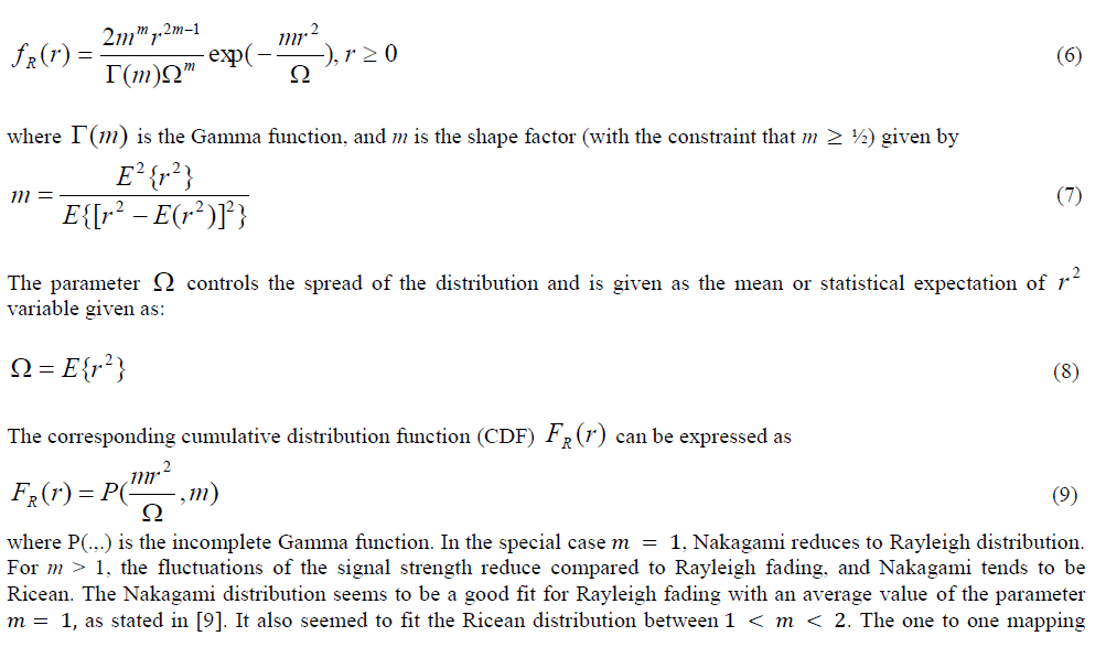
| C. Nakagami Fading Channel |
| Nakagami fading occurs for multipath scattering with relatively large delay-time spreads, with different clusters of reflected waves. Within any one cluster, the phases of individual reflected waves are random, but the delay times are approximately equal for all waves. As a result the envelope of each cumulated cluster signal is Rayleigh distributed. The average time delay is assumed to differ significantly between clusters. When the delay times also significantly exceed the bit duration of a digital link, the different clusters produce serious inter-symbol interference (ISI), and thus the multipath self-interference then approximates the case of co-channel interference by multiple in coherent Rayleighfading signals. In the following we state some important facts related to Nakagami fading. |
| ïÃâ÷ If the envelope is Nakagami distributed, the corresponding instantaneous power is Gamma distributed. |
| ïÃâ÷ Nakagami fading is described by „ïÿýïÿýâÃâ¬ÃŸ parameter as defined in equation 6. The parameter ïÿýïÿý is called the 'shape factor' of the Nakagami or the Gamma distribution. |
| ïÃâ÷ In the special caseïÿýïÿý = 1, Rayleigh fading is recovered (from Nakagami distribution), but with an exponentially distributed instantaneous power. |
| ïÃâ÷ For ïÿýïÿý > 1, the fluctuations of the signal strength reduce compared to Rayleigh fading. |
| It is possible to describe both Rayleigh and Ricean fading with the help of a single model using the Nakagami distribution [7]. Attempts have been made to find one-to-one mapping between Nakagami and Rayleigh distributions. The fading model for the received signal envelope, proposed by Nakagami, has the PDF f (r) R given by |
 |
 |
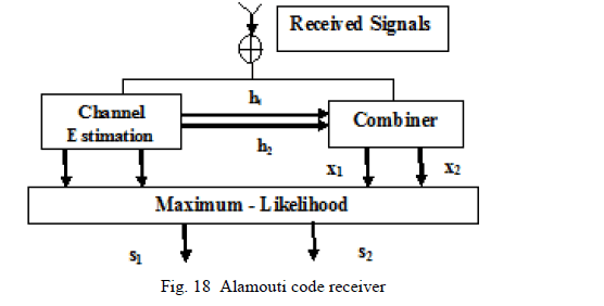
TECHNIQUES TO MITIGATE FADING EFFECTS
|
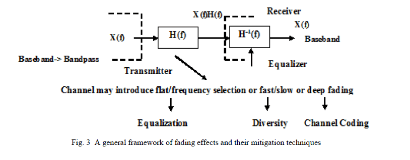
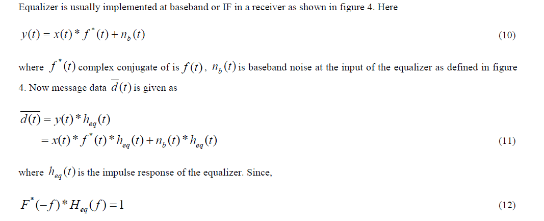
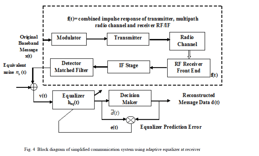
| Mobile communications require signal processing techniques that improve the link performance. Equalization, diversity and channel coding are some improvement techniques for channel impairments. |
| Equalization compensates for ISI created by multipath within time dispersive channels. An equalizer within a receiver compensates for the average range of expected channel amplitude and delay characteristics. In other words, an equalizer is a filter at the mobile receiver whose impulse response is the reciprocal (inverse) of the channel impulse response. As such equalizers find their use in frequency selective fading channels. If the channel impulse response beHc(f), the equalizer should have the transfer function given by Heq(f) = 1/Hc(f). |
| Channel coding improves the performance of mobile communication link by adding redundant data bits in transmitted message. Channel Coding is used to correct deep fading or spectral null [11]. A general framework of fading effects and their mitigation techniques is shown in figure 3. |
| Diversity is another technique used to compensate fast fading and is usually implemented using two or more receiving antennas. It is based on the fact that individual channels experience different levels of fading and interference. Multiple versions (or replicas) of the same signal may be transmitted and/or received and combined in the receiver. It is usually employed to reduce the depths and duration of the fades experienced by a receiver in a fading channel [3]. |
 |
| A. Equalization |
| ISI has been identified as one of the major obstacles to high speed data transmission over mobile radio channels. If the modulation bandwidth exceeds the coherence bandwidth of the radio channel (i.e., frequency selective fading), modulation pulses are spread in time, causing ISI. Depending on the transmission media, the main causes for ISI are band limiting in the cable lines and multipath propagation in cellular communication.c |
| For a reliable digital transmission system it is necessary to reduce the effects of ISI. The needs for equalizers [12] arise from the fact that the channel is dispersive in both amplitude and phase which results in the interference of the transmitted signals with one another. The design of the transmitters and receivers depends on the assumption that the channel transfer function is known. But, in most of the digital communications applications, the channel transfer function is not known at enough level to incorporate appropriate filters to remove the channel effect at the transmitters and receivers [13]. For example, in circuit switching communications, the channel transfer function is usually constant, but it changes for every different path from the transmitter to the receiver. It is worthwhile to mention here that there are some non-stationary channels like wireless communications. These channels transfer functions vary with time, so that it is not possible to use an optimum filter for these types of channels. This problem can be solved by equalizers. Equalizer is meant to work in such a way that BER should be low at high SNR level. Equalizer gives the inverse of channel to the received signal and combination of channel and equalizer gives a flat frequency response and linear phase [14-16]. An equalizer at the front end of a receiver compensates for the average range of expected channel amplitude and delay characteristics. |
 |
| Thus, if the channel is frequency selective, equalizer enhances the frequency components with small amplitudes and attenuates the strong frequencies in the received frequency response [17]. |
| As the mobile fading channels are random and time varying, equalizers must track the time-varying characteristics of the mobile channel and therefore should be time varying or adaptive. |
 |
| 1) Disadvantages of Equalization |
| ïÃâ÷ Even though the channel impulse response has finite length, the impulse response of the equalizer needs to be infinitely long. |
| ïÃâ÷ At some frequencies the received signal may be weak at some time instants. To compensate, the magnitude of the zero forcing equalizer grows very large. As a consequence any noise added after the channel gets boosted by a large factor and destroys the overall SNR |
| ïÃâ÷ The basic limitation of a linear equalizer, such as transversal filter, is the poor performance on the channel having spectral nulls [18]. |
| ïÃâ÷ Slow convergence (due to Eigen value spread). |
| B. Channel Coding |
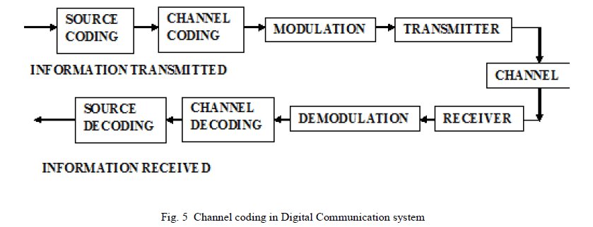
| In channel coding, redundant data bits are added in the transmitted message so that if an instantaneous fade occurs in the channel, the data may still be recovered at the receiver without the request of retransmission. This is what is called forward error correction. A channel coder maps the transmitted message into another specific code sequence containing more bits. Coded message is then modulated for transmission in the wireless channel [19]. A linear (n, k) block code is an example which maps k-bit messages into n-bit coded words. Channel Coding is used by both transmitter and receiver to detect or correct errors introduced in the digital communication channel [20]. Figure 5 below shows the channel coding concept in digital communication system. |
 |
| 1) Advantages of Channel Coding |
| ïÃâ÷ Channel coding deals with error control techniques. If the data at the output of a communications system has incurred errors that are too frequent for the desired use, the errors can often be reduced by using a number of techniques. |
| ïÃâ÷ Coding permits an increased rate of information transfer at a fixed (specified) bit or symbol error rate, or a reduced error rate for a fixed transfer rate. |
| 2) Noise Channel Coding Theorem |
| In information theory, the noisy-channel coding theorem (sometimes Shannon's theorem), establishes that for any given degree of noise contamination of a communication channel, it is possible to communicate discrete data (digital information) nearly error-free up to a computable maximum rate through the channel. This result was presented by Claude Shannon in 1948 [2]. Stated by Shannon, the theorem describes the maximum possible efficiency or trade-off of error-correcting methods versus levels of noise interference and data corruption. Shannon's theorem has wide-ranging applications in both communications and data storage. This theorem is of foundational importance to the modern field of information theory and coding. Shannon only gave an outline of the proof. The first rigorous proof is due to Amiel Feinstein in 1954. |
| The Shannon theorem states that |
| Given a noisy channel with channel capacity C and information transmitted at a rate R, then if ïÿýïÿý < ïÿýïÿý there exist codes that allow the probability of error at the receiver to be made arbitrarily small. This means that, theoretically, it is possible to transmit information nearly without error at any rate below a limiting rate, C [19],[21]. |
| The converse is also important. If ïÿýïÿý > ïÿýïÿý, the probability of error at the receiver cannot be made arbitrarily small simply by using coding. All codes will have a probability of error greater than a certain positive minimal level, and this level increases as the rate increases. So, information cannot be guaranteed to be transmitted reliably across a channel at rates beyond the channel capacity [22]. The theorem does not address the rare situation in which rate and capacity are equal. The channel capacity C can be calculated from the physical properties of a channel; we now give here the mathematical statement for a band-limited channel with Gaussian noise, using the Shannon–Hartley theorem. |
Mathematical Statement
|
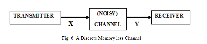
| For every discrete memory less channel (see figure 6), the channel capacity C is defined as |
 |
 |
| Corollary 1: While dealing within maximum channel capacity, introduction of redundant bits increase the transmitter rate and hence bandwidth requirement also increases, while decreasing the bandwidth efficiency, but it also decreases the BER. |
| Corollary 2: If data redundancy is not introduced in a wideband noisy environment, errors free performance in not possible (for example, Code Division Multiple Access (CDMA) communication in 3G mobile phones). |
DIVERSITY AND COMBINING TECHNIQUES
|
| In wireless transmission, signal quality suffers severe degradations due to effects like fading caused by multipath propagation. To reduce such effects, diversity, as proposed by [6], can be used to transfer different samples of same signal (that is replica of same signal) over essentially independent channels. There are several approaches to implement diversity in wireless transmission. Diversity exploits the random nature of radio propagation by finding independent signal paths for communication. As there is more than one path to select, both the instantaneous and average SNRs at receiver may be optimized significantly. Diversity decisions are usually made by receiver. Unlike equalization, diversity requires no training overhead as a training sequence. Note that if the distance between two receivers is a multiple of λ 2, there might occur a destructive interference between the two signals, where λ is the wavelength of the carrier. Hence receivers in diversity technique are used in such a way that the signal received by one is independent of the other. |
| A. Types of Diversity |
| There are several different kinds of diversity employed in wireless communication systems, namely, frequency, time, and space diversities. |
| 1) Frequency Diversity: |
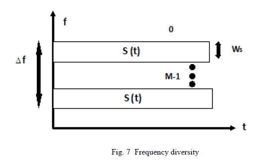
| Frequency diversity utilizes transmission of the same signal at two different well-spaced frequency carriers achieving two independently fading versions of a signal. Frequency diversity is the simultaneous use of multiple frequencies to transmit information. This technique is used to mitigate the effects of multipath fading since the component wavelengths for different frequencies possibly result in different and uncorrelated fading characteristics [6]. It is most likely that the signals will not suffer the same level of attenuation at different frequencies, the receiver picks up the strongest signal to control of the transmission. The waves transmitted on different frequencies effectively induce different multipath structure in the propagation media. The replicas of the transmitted signal are transmitted to the receiver in the form of redundancy in the frequency domain. As shown in figure 7, signal s(t) is modulated through M different carriers in the frequency interval Ws. The separation between the carriers should be at least the coherent bandwidth Δf and it represents the frequency separation of uncorrelated signals. Here different copies undergo independent fading [23]. Thus the total transmitted power is split among the carriers. It is obviously a cost-effective mechanism to use because of difficulties to generate several transmitted signals and the combining signals received at several different frequencies simultaneously. Frequency diversity consumes extra bandwidth. |
 |
| 2) Time Diversity: |
| Time diversity is achieved by transmitting same bit of information repetitively at short time intervals. A redundant forward error correction code is added and message is spread in time by means of bit-interleaving before it is transmitted. Thus, error bursts are avoided, which simplifies the error correction. Another constraint in time diversity is that the time difference between two transmissions should be large compared to the time is takes the mobile antenna to move half a wavelength. In systems with stationary antennas, such as indoor wireless communication, time diversity will be less effective as the channel characteristics do not change very much with time. However, time diversity may be helpful if uncorrelated interference signals are experienced during successive attempts [6]. |
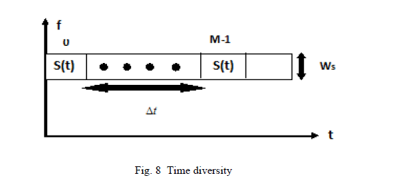
| As shown in figure 8, desired signal s(t) is transmitted in M different periods of time i.e., each symbol is transmitted M times in the frequency interval Ws. The interval between transmissions of same symbol should be at least the coherence time Δt. Here also it is assumed that different copies undergo independent fading to different degrees. This leads to reduction in efficiency (effective data rate < real data rate). |
 |
| 3) Space Diversity |
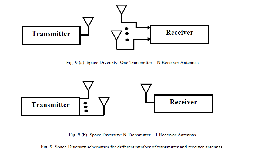
| Space diversity is considered as a method of transmission or reception, or both, in which the effects of fading are minimized by the simultaneous use of two or more physically separated antennas, ideally separated by one half or more wavelengths. Signals received from spatially separated antennas have uncorrelated envelopes. Space diversity, which has been widely exploited in wireless communications to combat channel fading, promises higher data rates and larger network coverage [3] . Space diversity is achieved by using multiple antennas at the base station or at the mobile station or at both ends. Spatial diversity techniques can effectively mitigate the performance deterioration caused by fading, without imposing delay or bandwidth expansion and this property is clearly desirable from efficiency and system usability points of view [23]. Figures 9(a) and 9(b) consecutively shows a generalized concept of space diversity. |
 |
| 4) Rotated Diversity |
| Modulation diversity (MD) is also known as signal space diversity (SSD); this scheme can improve system performance without requiring additional bandwidth and power [24], [25]. The principle underlying the modulation diversity is based on the rotation of multi-dimensional signal constellation in which the components of the signal constellation points are sent over independent fading channels. In 2D signal constellation, the components are sent as in phase and quadrature phase for baseband transmission. |
| Signal space diversity (SSD) scheme achieves diversity gain in fading channels. The scheme is based on rotation of signal constellation and component-wise interleaving. Due to these operations, the decision boundaries for the SSD are no longer perpendicular. That is why different coordination approaches are required for the analysis of error rates as compared to conventional rectangular coordinates [26]. In this line, reference [27] explores the signal space diversity (SSD) scheme combined with receiver MRC in order to achieve more diversity gain in fading environments. Rotation diversity makes use of an interleaver and de-interleaver pair with in-phase and quadrature components of the received signals being affected by independent channel fading coefficients. These fading coefficients called channel state information (CSI) are assumed known at the receiver. Error performance has been studied by many researchers for rotated signal constellation [24]-[29]. |
| B. Combining Methods |
| Several copies of the transmitted signal undergo independent fading and are combined at the receiver in a way to increase overall received power. Different types of diversity call for different combining methods. Here, we review several common diversity combining methods. |
| 1) Combining Techniques for Microscopic Diversity |
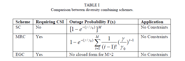
| Microscopic Diversity deals with short term fading effects. In this case what follows is to obtain a number of signals with equal mean power through the use of diversity schemes. Many researchers have been working on combining techniques in different environments [30]-[41]. Three types of linear diversity combining schemes are popular: |
| ïÃâ÷ Selection Combining (SC) |
| ïÃâ÷ Maximum Ratio Combining (MRC) |
| ïÃâ÷ Equal Gain Combining (EGC) |
Selection Combining
|
 |
 |
Maximum Ratio Combining
|
| In MRC, all the branches are taken into consideration simultaneously. Each of the branch signals is weighted with a gain factor proportional to its own SNR. The MRC scheme requires that the signals be added up after bringing them to the same phase [34], [35]. The gain associated with the ith branch is decided by the SNR of the corresponding branch. If i a is the signal envelope in the ïÿýïÿýïÿýïÿýâÃâÃŽ branch then the combined signal envelope is given as |
 |
 |
| The main challenge in MRC combining is co-phasing of the incoming branches after weighting them [37]. Figure 11 sho ws a simplified diagram of Maximal Ratio Combiner technique. Co-phasing and summing is done for adding up the weighted branch signals in phase. Modern DSP techniques and digital receivers are now making this optimal form, as it gives the best statistical reduction of fading of any known linear diversity combiner [38]. |
 |
Equal Gain Combining
|
| It is a co-phase combining that brings all phases to a common point and combines them. The combined signal is the sum of the instantaneous fading envelopes of the individual branches. |
| Thus co-phasing and summing is done on the branches which are received directly i.e. g s i ' of the MRC scheme are made equal to 1, for all ïÿýïÿý = 1, 2, 3, … . . ïÿýïÿý. The performance of the Equal Gain Combining is worse than the MRC [39]. The combined signal envelop is given by |
 |
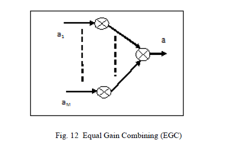 |
| and the resulting SNR is |
 |
 |
INTRODUCTION TO MIMO WIRELESS COMMUNICATION
|
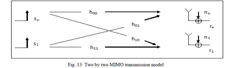
| Multiple-input multiple-output (MIMO) systems are a natural extension of further developments in antenna array communication. Although the advantages of multiple receive antennas, such as gain and spatial diversity, have been investigated for some time [1],[35],[42], the use of transmit diversity has only been studied in the past [43],[44]. The advantages of MIMO over SISO communications are currently receiving significant attention [45], [46]. Under certain environmental conditions, the power requirements associated with high spectral-efficient communication can be significantly reduced by avoiding the compressive region of the information-theoretic capacity bound. To increase the reliability of the communication systems, multiple antennas can be installed at the transmitter or/and at the receiver. Alamouti code [47] is considered as the simplest transmit diversity scheme while the receive diversity includes combining methods such as, maximum ratio, equal gain and selection combining. The idea behind multiple antenna diversity is to supply the receiver by multiple replicas of the same signal transmitted via independent fading channels. Let us describe the MIMO channel in the matrix representation. In the simplest scenario, two data streams are transmitted via two transmit antennas (see figure 13). In contrast to SISO, this generates 4 individual transmission paths, each associated with one complex transmission coefficient. The resulting two by two MIMO transmission channel can be represented mathematically as two by two matrices with 4 complex valued matrix elements. Each of the 2 receivers estimates two of the channel matrix elements based on known reference elements. |
 |
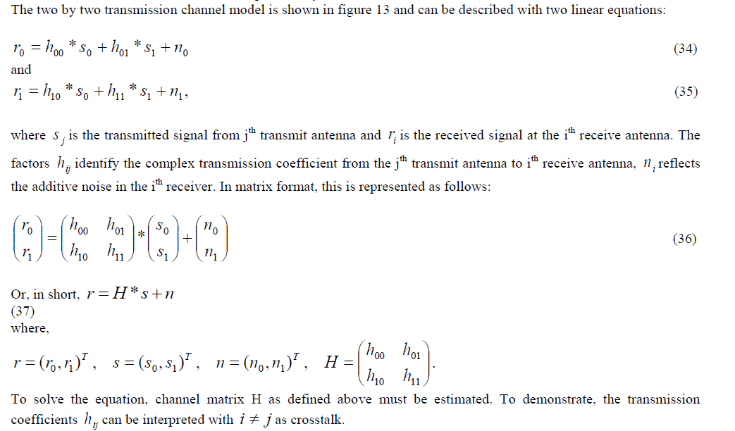 |
| One benefit of multiple antenna systems is that it can tremendously increase the channel capacity by sending independent signals from different transmitting antennas. An example of such category of multiple antenna technologies is the Bell Laboratories Layered Space-Time (BLAST) spatial multiplexing schemes that boost up the channel capacity. In addition, smart antenna technique can also significantly increase the data rate and improve the quality of wireless transmission limited by interference, local scattering and multipath propagation. Multiple User Multiple Input Multiple Output (MU-MIMO) systems can provide higher data rates than Single User Multiple Input Multiple Output (SU-MIMO) by transmitting signals to multiple mobile stations (MSs) simultaneously over the same spectrum. Previous studies mainly focused on maximizing the spectral efficiency of MU-MIMO systems, some examples of which can be found in [11], [48], [49]. A trade-off between the spatial multiplexing gain and the inter-user interference, spectral efficient mode switching between SU-MIMO and MU-MIMO was presented in [49]. Figure 14 summarizes the different multiple antenna technologies. |
 |
| A. MIMO Types |
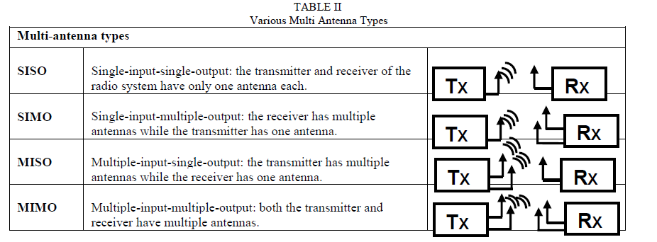
| The space diversity scheme has become more attractive diversity technique in recent years due to its flexibility of use with other diversity techniques [50]. The MIMO system can be broadly classified as Multi-antenna type and Cooperative MIMO type. |
| 1) Multi-Antenna Types |
| In multi-antenna types, multiple antennas are placed at the transmitter and receiver. This multi-antenna communication is categorized in three different forms, based on the number of antenna. These are known as multiple-input-single output (MISO), single-input-multiple-output (SIMO) and multiple-input-multiple-output (MIMO) as shown in Table 2. By using space diversity MIMO techniques have shown tremendous improvements in reliability and throughput in wireless communication systems. The size, cost and hardware constraints in the use of MIMO techniques may not always be feasible especially in small portable devices such as cell phones. To address this problem, the concept of cooperative diversity was introduced. |
 |
| 2) Cooperative MIMO |
| In a transmission between a single transmitting station and a single receiving station, MIMO can be realized by using multiple antennas at the transmitting and receiving stations. Although the same approach can be used to implement MIMO in an infrastructure-based relay system, there is a fundamental difference in that relay transmissions are made from multiple transmitting stations to a single receiving station. The signal transmission from multiple sources to a single destination can be thought of as if the signals are from different antenna elements of a single source. |
| The term cooperative MIMO is used to distinguish this scheme from the conventional one (without any cooperation between the transmitting stations) in which identical signals are transmitted. |
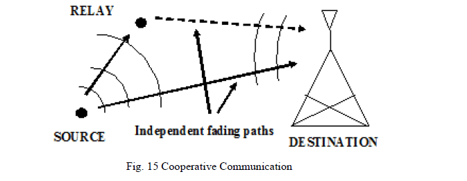
| Cooperative MIMO can be used to enhance the performance of an infrastructure-based relay system by having the Base Station (BS) and multiple Relay Stations (RS) participating in the relay transmission to perform identical space-time encoding processes but transmit different layers of the space-time code. For example, in each hop of the relay transmission, all cooperating stations generate a common orthogonal space-time code (OSTBC) matrix, and individual transmitting stations transmit only those columns designated to them [51-53]. One notable advantage of cooperative MIMO in relay transmissions is that spatial multiplexing gain can be achieved; even if the transmitting stations do not have multiple transmit antennas, as long as the receiving station has multiple antennas. Figure 15 gives an illustration of cooperative communication. |
 |
| B. MIMO Diversity |
| In communication systems, we are faced with the challenge to increase the reliability of the communication operation between transmitter and receiver while maintaining a high spectral efficiency. The ultimate solution relies in the use of diversity, which can be viewed as a form of redundancy [54]. Multiple antenna systems have been known to increase diversity to combat channel fading. Each pair of transmit and receive antennas provides a signal path from the transmitter to the receiver. By sending signals that carry the same information through different paths, multiple independently faded replicas of the data symbol can be obtained at the receiver end; hence more reliable reception is achieved [47] but with more redundancy. In a slow Rayleigh fading environment with one transmit and N receive antennas, the transmitted signal is passed through N different paths. If the fading is independent across antenna pairs, a maximal diversity gain of N can be achieved [3]. The average error probability has been found to decay by 1 ïÃÂç N (where γ is the average SNR) at high SNR in contrast to γ for the single input single output (SISO) system. With multiple transmit antennas M and one receive antenna, the underlying idea is still averaging over multiple path gains to increase the reliability. It has been shown that with M transmit antennas and one receive antenna, a diversity gain within 0.1dB that of N receive antennas with one transmit antenna can be achieved [11], [55]. |
| 1) Introduction to Transmit Diversity Techniques |
| Antenna arrays can be used in wireless communications systems because of their potential capabilities in combating fading, mitigating multipath distortion, and enhancing signal-to-noise ratio. Antenna arrays are predominantly used in the receive mode; however, there has been an increased interest in using antenna arrays in the transmit mode also. Transmit diversity provides essentially the same benefits as receive diversity and can also be extended to perform transmit-beam forming [56-62]. |
| The major problem associated with the receive diversity approach is the cost, size and power of the remote units. The use of multiple antennas and carriers at radio frequency (RF) makes the remote units larger in size and more expensive. As a result, diversity techniques have almost exclusively been applied to base stations to improve their reception quality. Since a base station often serves several thousands of remote units, it finds less expensive to add equipments to the base stations rather than to the remote units. For this reason, transmit diversity schemes are very attractive. The simple transmit diversity scheme suggested by Alamouti and the space time coding suggested by V. Tarokh et al. [63] triggered research in this area. Several transmission schemes such as spatial multiplexing, spatial diversity (space-time coding) and Smart Antennas & beam forming techniques have been proposed that utilize the MIMO channel in different ways. |
| In spatial multiplexing techniques, information is demultiplexed and independently transmitted over multiple antennas. This will increase data rate due to multiplexing but diversity gain is reduced because of higher error rate. Spatial diversity techniques transmit the same information over multiple antennas improving error rate and in turn diversity gain is achieved. |
| Transmit diversity can be combined with error control coding to have better error performance in the link. A more optimal scheme is the joint design of transmit diversity, error control coding and modulation [23]. The technique is called Space-Time Coding (STC). With STC, diversity and coding gain can be achieved without bandwidth expansion. Large capacity gains have been shown possible by using MIMO systems, and STC is a way to approach the capacity limit. Channel capacity formulas for different combinations of transmit and receive antennas can be found in [65]. In practice, multiple diversity schemes are usually used together in practices. |
| 2) Spatial Diversity Techniques |
| Spatial Diversity can be achieved by deploying multiple transmit antennas (transmit diversity) or multiple receive antennas (receive diversity) with sufficient spacing between antennas. The main idea of transmit diversity is to provide a diversity and/or coding gain by sending redundant signals over multiple transmit antennas [23], [63]. At the receiver we use a combining scheme which eliminates spatial interference from other antennas. In all the combining schemes it is assumed that the channel state information (CSI) is known to the receiver. Unlike frequency diversity where additional bandwidth may be required and time diversity where additional time slots are required, spatial diversity does not require additional bandwidth or transmission time. |
Closed-Loop Transmit Diversity (CLTD) Scheme
|
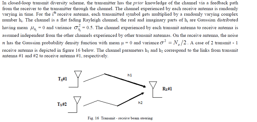 |
| On the receive antenna RX, the received signal is, |
 |
 |
| Complex Orthogonal Space-Time Codes |
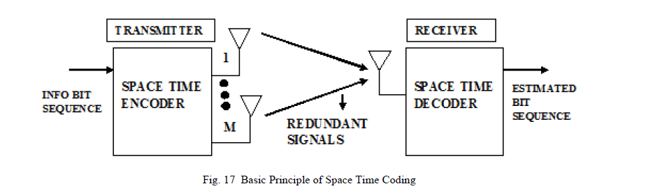
| The main idea of transmit diversity is to provide a diversity (gain) by sending redundant signals over multiple transmit antennas [9]. At the receiver we use a combining scheme which eliminates spatial interference from other antennas. In all these schemes it is assumed that channel state information is known to the receiver. However, the value of transmit diversity was only recognized in 1998, when Alamouti proposed a simple technique for two transmit antennas [54]. In the same year, Tarokh, Seshadri, and Calderbank presented their space-time trellis codes (STTCs) [64], which are twodimensional coding schemes for systems with multiple transmit antennas. The basic structure of a space-time coding scheme is illustrated in figure 17. The pre-processing of the redundant transmission signals is performed by the spacetime encoder, which depends very much on the specific scheme under consideration. At the receiver, corresponding detection/decoding process is carried out by space-time decoder. |
 |
| Motivated by the simple receiver structure of [47], orthogonal space-time block codes (OSTBCs) were introduced in [56], which constitute a generalization of AlamoutiâÃâ¬ÃŸs scheme with more than two transmit antennas. OSTBCs are designed to achieve full diversity with regard to the number of transmit and receive antennas. In contrast to STTCs, OSTBCs do not offer any additional coding gain. OSTBCs are based on the mathematical theory of orthogonal designs, which dates back to the 1890s. Orthogonal designs are a special class of orthogonal matrices. In general, the use of OSTBCs causes a rate loss when compared to an un-encoded single-antenna system. Given a complex-valued modulation scheme, the only full-rate OSTBC is AlamoutiâÃâ¬ÃŸs transmit diversity scheme [3] for two transmit antennas. In [56] it was shown that rate – ½ OSTBCs for complex-valued modulation schemes can be constructed for any number of transmit antennas. However, the following conditions must be satisfied. |
| 1. Square transmission matrix (that is, number of transmit antennas Nt equals the number of used time slots m). |
| 2. A unity code rate (number of used time slots m equal to number of transmitted symbols). |
| 3. Orthogonality of the transmission matrix S in the time and space domains (SSH = SHS) where SH is the conjugate transpose of S. |
| As said earlier, the simplest complex orthogonal space-time code is the Alamouti code which uses two transmit antennas and one receive antenna. Furthermore, this scheme requires that the fading channel envelope to remain constant over two time slots. |
 |
 |
Generalized Complex Orthogonal Space-Time Codes
|
| Tarokh, Jafarkhani, and Calderbank [56] performed analysis of space-time codes with more than two antennas based on complex orthogonal designs. Generalized complex orthogonal designs are distinguished from Alamouti code in the sense that the transmission matrix is non-square (that is, number of used time slots ≠ number of transmit antennas) and has fractional code rate (number of transmitted symbols < number of used time slots). Orthogonality of the transmission matrix is only guaranteed in the time sense. |
| As a consequence of these properties, the spectral efficiency is reduced and the number of time slots is increased over which the channel property does not vary. The transmission matrix of a generalized complex space-time code with 3 antennas, 4 transmitted symbols (si, i = 1, 2, 3 and 4) and 8 used time slots is given by [65]. |
 |
| family which includes Vertical-BLAST (V-BLAST), Diagonal-BLAST (D-BLAST) and Turbo-BLAST (T-BLAST). The acronym BLAST stands for “Bell Laboratories Layered Space-Time”. |
Diagonal-BLAST
|
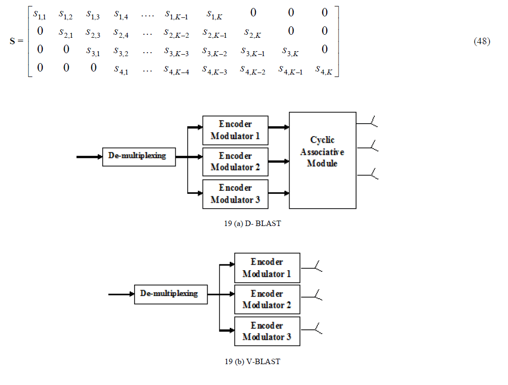
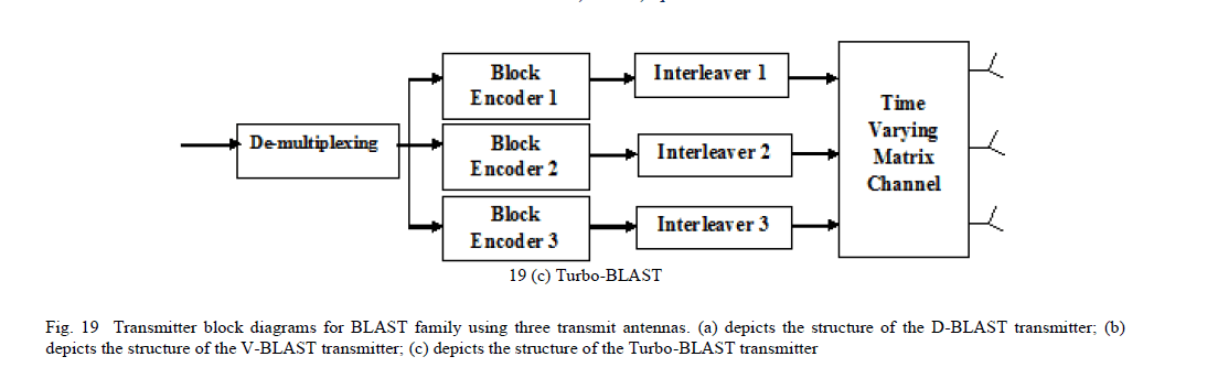
| D-BLAST was originally proposed by G. J. Foschini [67] in 1996. In D-BLAST, the symbols to be transmitted are arranged on the diagonals of the space-time transmission matrix with the elements under the diagonal padded with zeros. Fig. 19 (a) depicts the structure of the D-BLAST transmitter for three transmit antennas. At first, the bit stream is de-multiplexed into three parallel streams which are encoded and modulated independently. Encoded-modulated bit streams are cycled over time. Equation (55) is an example of the transmission matrix S when using four transmit antennas. The first diagonal of S is transmitted via the first antenna; the second diagonal is transmitted via antenna 2, and so on. |
Vertical-BLAST
|
| A simplified version of D-BLAST was proposed by P. Wolniansky known as Vertical-BLAST or V-BLAST [68] in 1998. In V-BLAST, incoming data stream is de-multiplexed into Nt streams each of which is encoded and modulated independently and transmitted to its antenna. V-BLAST high-level diagram is depicted in Fig. 19 (b) where three antennas are used at the transmit side. Compared to D-BLAST, V-BLAST does not include cycling over time, and hence complexity is significantly reduced. In addition, unlike D-BLAST, V-BLAST does not include any space-time wastage. At the receiver, transmitted symbols can be decoded using ordered serial interference-cancellation (OSIC) detector. For the OSIC to work properly, the number of receive antennas Nr must be at least as large as the number of transmit antennas Nt. |
 |
 |
Turbo-BLAST
|
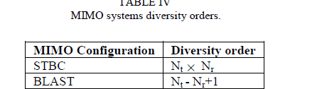
| Turbo-BLAST was first described by Sellathurai and Haykin [69] in 2002. The Turbo-BLAST transmitter structure is depicted in Fig. 19 (c). The data stream bits are firstly de-multiplexed into Nt parallel streams which are encoded independently using the block encoder (outer encoder). The output streams of the outer encoder are interleaved independently and passed to the inner encoder. The objective of the outer encoder (channel encoder) is to achieve random-layered space-time (RLST) coding. We list in Table 4 a comparison between diversity order of the different space-time coding and the BLAST family schemes. |
 |
MIMO-OFDM FOR FUTURE BROADBAND WIRELESS ACCESS
|
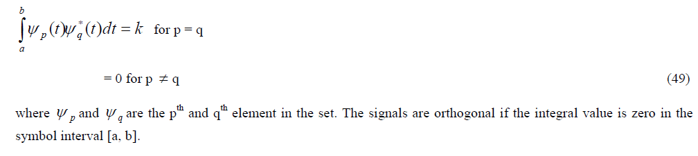
| Orthogonal Frequency Division Multiplexing (OFDM) is a form of multi-carrier modulation where the carrier spacing is carefully selected so that each sub-carrier is orthogonal to the other sub carriers. Two signals are orthogonal in some time interval if their inner product is zero over the interval. Orthogonality can be achieved by carefully selecting carrier spacing (for example carrier spacing equal to reciprocal of useful symbol period). As the sub-carriers are orthogonal, the spectrum of each carrier has a null at center frequency of each of other carriers in the system. This results in no interference between the carriers, allowing them to be spaced as close as theoretically possible. Mathematically, suppose we have a set of signals ïÃÂù [70]. |
 |
| In advance broad band access in LAN and MAN, OFDM is used with different combinations and techniques e.g. MIMO. This can combat better against multipath fading (deep fading) and also supports high data rate. Over radio link like HDTV supports multimedia applications. MIMO-OFDM reduces the receiver complexities and manipulations as they distribute the data information over multiple sub carriers and transmits at different frequency levels which are helpful in spectral efficiency and error control transmission. MIMO-OFDM sends stream of independent data information to increase spatial rate over different antennas. |
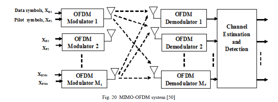 |
| In OFDM the bandwidth is divided into narrow band flat fading channels and data is transmitted on each channel as depicted in figure 20. Thus we find that it is a technique which converts frequency selective channels to many flat fading channels and to each of sub channels where the MIMO scheme is applied [71]. Lipson wireless first introduced the MIMO-OFDM scheme. It allows transmission and successful communication in non-LOS path (such as base station using MIMO-OFDM utilizes multipath scenario [72]). |
| Potential researches are going on over MIMO systems in an effort to increase data rate and capacity. With implantation of OFDM with MIMO many ideas has been solved in diversity and capacity of channel, thus attaining great spectral efficient environment [73]. On other hand the complex equalization can be minimized with great improvement and potential by considering MIMO-OFDM scheme which almost eliminate the complexity of equalization. |
| Comparison of OFDM with MIMO-OFDM |
| 1) OFDM is characterized by higher data rate. In this the entire channel is divided into narrow parallel sub channels, thereby increasing the symbol duration and reducing the ISI effect caused by the multi-path components. STC characterized by high code efficiency and good performance, is a promising technique to improve the efficiency and performance of OFDM systems. For wideband transmission space–time processing must be used to mitigate ISI. But employing OFDM-SISO system with flat Rayleigh fading or narrowband channels, the complexity of the space–time processing increases with the bandwidth, and the performance substantially degrades when estimated channel parameters are used. |
| 2) Multiple transmit and receive antennas can be used with OFDM to further improve system performance. Thus more bandwidth is required for signal transmission at still higher data-rate. However, due to spectral limitations, it is often impractical and expensive to increase bandwidth. In this case, usages of multiple transmit and receive antennas for spectrally efficient transmission is an alternative solution. |
| 3) In MIMO-OFDM focus is enhanced channel estimation and signal detection. In MIMO-OFDM system to achieve transmit diversity gain and detect the transmitted signal, a space time processor must extract the required signals for space time decoders. Both space time processor and space time decoding require CSI [70]. |
| 4) MIMO system can improve the channel system capacity by a factor of the minimum number of transmit and receive antennas. With more receive antennas, MIMO-OFDM results in increased SNR and less word error rates (WER). Therefore MIMO-OFDM is the promising technique for highly spectral efficient broad band transmission and it can be effectively used in high-data-rate wireless systems. |
PERFORMANCE IMPROVEMENTS
|
| The performance improvements resulting from the use of MIMO systems are due to array gain, diversity gain and interference reduction. Here we briefly review each of these leverages in a system with MT transmit and MR receive antennas. |
| A. Array Gain |
| Array gain can be made available through processing at both transmitter and receiver. These results in an increase in average receive SNR due to a coherent combining effect. Transmit and / or receive array gain depends on the number of transmit and receive antennas and require channel knowledge in the transmitter and receiver, respectively. Channel knowledge is typically available in the receiver whereas CSI in the transmitter is difficult to maintain. |
| B. Diversity Gain |
| The signal power in a wireless channel fades randomly. Diversity techniques rely on transmitting the signal over multiple (ideally) independently fading paths (in time/frequency/space). Spatial (or antenna) diversity is preferred over time/frequency diversity as it does not incur excess transmission time or bandwidth. If the − ïÿýïÿýïÿýïÿý links composing the MIMO channel fade independently and the transmitted signal is suitably recovered, then the receiver combines the arriving signals such that the resultant signal exhibits considerably reduced amplitude variability in comparison to a SISO link and we get th - order diversity. Using suitable transmit signals it is possible to extract spatial diversity gain in the absence of channel knowledge at the transmitter. The corresponding technique is known as space–time coding [56], [64], [74]. |
| C. Interference Reduction |
| Co-channel interference results due to frequency reuse in wireless channels. When multiple antennas are used, the differentiation between the spatial signatures of the desired signal and co channel signals can be exploited to reduce interference. Interference reduction requires knowledge of the desired signalâÃâ¬ÃŸs channel not that of interfererâÃâ¬ÃŸs channel. Interference reduction (or avoidance) can also be implemented at the transmitter, where the goal is to minimize the interference energy sent toward the co channel users while delivering the signal to the desired user. Interference reduction allows aggressive frequency reuse and thereby increases multi-cell capacity. It is not possible to exploit all the leverages of MIMO technology simultaneously due to conflicting demands on the spatial degrees of freedom (or number of antennas). The degree to which these conflicts are resolved depends upon the signaling scheme and transceiver design. |
MIMO RELAY CHANNELS
|
| The concept of relay originated as an information theoretical scenario in a paper “Capacity theorems for the relay channel” by T. M. Cover and A. A. E. Gamal in 1979 [75]. In this paper they considered the main channel along with a relay channel, where a relay acts as a helper node in the transmission of information bits. The definition of a relay as provided in IEEE 802.16j is as follows: |
| “A generalized equipment set, dependent on a multi-hop relay base station (MR-BS) providing connectivity, to other RSs or subscriber stations (SS).” A relay can be thought of as a miniature base station that enjoys line of sight connectivity with another relay or a base station. Unlike a base station, a relay is not connected to the wired backhaul. Several relaying protocols are proposed, such as amplify-and-forward (AF), decode-and-forward (DF) and coded cooperation (CC) [50],[76-79]. Many cooperation strategies based on the relay channel have been proposed in recent years. The strategies falls into one of the following three categories based on relay behavior. |
| A. Amplify and Forward: |
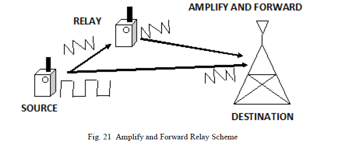
| This strategy represents the simplest way that a relay node may cooperate. Under this scheme, the relay buffers the source nodeâÃâ¬ÃŸs analog transmission over some predetermined time interval (i.e. frame, codeword, etc. which is denoted as “cooperation period”) and retransmits an amplified copy of the signal during the following cooperation period as shown in figure 21 below. The main advantage of this scheme are simplicity and low cost. This scheme has the negative side effect of amplifying the relayâÃâ¬ÃŸs received noise. However, it has been shown in [50],[78] that this scheme provides gains over non-cooperation in terms of outage probability and can even outperform decode and forward relaying in certain network geometries. Since relay does not perform any kind of decoding, this transmission protocol has reduced hardware complexity. Thus, this cooperation highly depends on the condition of channel between source and the relay. The processing of sampling, amplifying and retransmitting analogue values is another potential challenge in this scheme. |
 |
| B. Decode and Forward: |
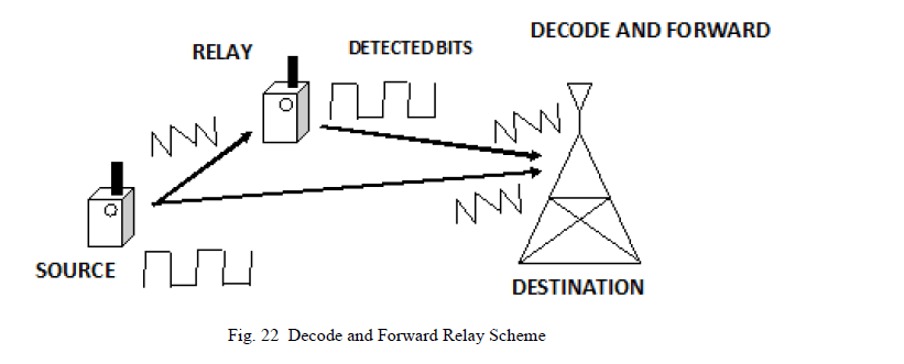
| In this method, the relay decodes the received message from the sender, checks for errors and re-encodes to transmit to the destination. The receiver estimates the information signal using Maximal Ratio Combining. The relay can either decode the entire signal or it can perform symbol by symbol decoding [50]. When the relay decodes the received signal, the noise introduced in the information signal should be removed prior to decoding. Otherwise, it is more likely that the original signal could be corrupted. The destination must decode the signal completely. Hence, the destination must be aware of both the decoding techniques in order to fully decode the signal as shown in figure 22. In real time environments, there is less certainty that the decoded signals sent from the relay would again be noise affected. Nicholas Laneman has shown that the decode and forward method fails to attain full spatial diversity. In general, decode-and-forward outperforms amplify-and-forward relaying in cases where the relay can reliably decode the source nodeâÃâ¬ÃŸs message. |
 |
| C. Coded Cooperation |
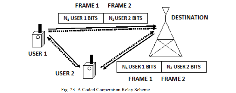
| Coded cooperation is a method that integrates cooperation into channel coding. It works by sending different portions of each userâÃâ¬ÃŸs code word via two independent fading paths. The basic idea is that each user tries to transmit incremental redundancy to its partner. Whenever that is not possible, users automatically revert to a non-cooperative mode. The key to the efficiency of coded cooperation is that all this is managed automatically through code design, with no feedback between the users [80]. |
| Consider that original codeword has ïÿýïÿý1 + ïÿýïÿý2 bits; puncturing this codeword down to N1 bits, we obtain the first partition, which itself is a valid (weaker) codeword. The remaining N2 bits in this example are the puncture bits. Likewise, data transmission period for each user is divided into two time segments of N1 and N2 bit intervals. Here we call these time intervals as frames. For the first frame, each user transmits a code word consisting of the N1-bit code partition. Each user also attempts to decode the transmission of its partner. If this attempt is successful, in the second frame the user calculates and transmits the second code partition of its partner, containing N2 code bits. Otherwise, the user transmits its own second partition, again containing N2 bits. Thus, each user always transmits a total of N = ïÿýïÿý1 + ïÿýïÿý2 bits per source block over two frames as shown in figure 23.The performance of the two-hop AF relay network has been studied in [81] for single relay and multiple relay under Rayleigh fading channels, and this is extended to Nakagami fading environment in [82] for i.i.d. case and for independent non-identical case [83]. Relay transmissions with nodes employing multiple antennas are gaining great interest. In [84], the tradeoff between the diversity and multiplexing is analyzed and the capacity bounds of MIMO relay channels have been found in [85] and the reference therein. |
 |
| In [86], SER is presented for beam forming in two-hop AF relay network with source and destination deploying multiple antennas. Capacity bounds for full-duplex MIMO relay channel were derived in [85], [87]. The authors of [88] derive optimal infinite-SNR diversity-multiplexing tradeoff for the half duplex MIMO relay channel and concluded that a compress- and-forward strategy is optimal in this sense. Recently, practical strategies have been developed for MIMO relaying. Both [89] and [84] derive the mutual-information-maximizing non regenerative linear relay for spatial multiplexing when the direct link is ignored. In [88] and [90], performance analysis of OSTBC transmission in cooperative relay network is presented for AF and DF protocols. |
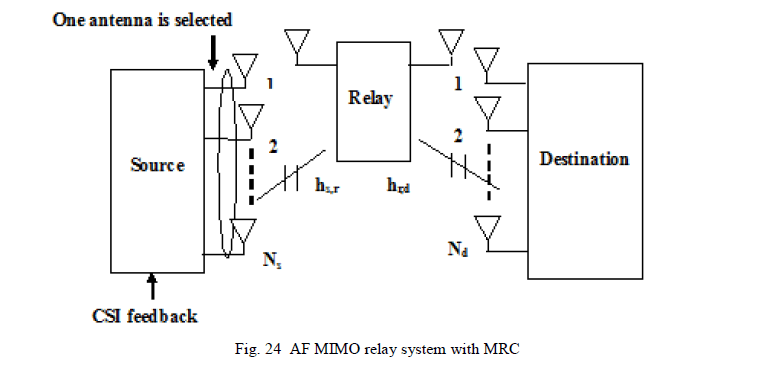
| Figure 24 depicts an Amplify and Forward MIMO relay system employing MRC diversity technique. We prefer MIMO relay channels because this application has great potential in wireless networks. For example, for transmissions from a base station (access point) to users, relay stations can be exploited to relay messages for end users. The motivation for using relay stations can be simply put as follows: |
| 1) In a cellular network, to ensure reliable communications, direct transmissions between the BS and users close to the cell boundary can be very expensive in terms of the transmission power required; and |
| 2) Existing RF technologies can accommodate only few antennas at the user end, indicating that current wireless systems cannot fully benefit from promising space–time techniques. By making use of relay stations (which can accommodate multiple antennas) to relay the message, the channel is effectively converted into a MIMO relay channel. Another application is to utilize relay nodes for cooperative communications in ad hoc networks, where the nodes close to the active transmitter and the receiver can relay data packets from the transmitter to the receiver (see, e.g., [80][91][92][93][94]). |
 |
CONCLUSION
|
| The demand for mobile data services has increased aggressively in the last few years and some mobile carriers have experienced even more growth numbers. According to a recent forecast, the global mobile data traffic is expected to become double every year through 2014, leading to a global compound annual growth rate of roughly 100%. Within the range of system development, LTE-Advanced and WiMAX - 2 can use up to 8x8 MIMO. Additionally new reference signals have been introduced to support both demodulation/ detection and channel state information estimation. Hence, special attention has been paid to the signaling for more advanced SU/MU-MIMO schemes. However, the crucial sensitivity of MIMO receivers to channel interference is the key challenges faced in cellular networks with the use of MIMO technology. On one hand, system designs should reduce transmit power and data rate in order to suppress the interference caused to the neighboring cells. On the other hand, MIMO systems by nature increases the amount of data transmitted and hence requires a larger received signal to interference noise power ration (SINR). Advanced signal processing techniques at the receiver and transmitter as a means of reducing or cancelling the interference effects have been used. |
| Thus, with the help of this article, we found that MIMO system is nothing but the use of multiple antennas at both transmitter and receiver. This is used to improve the link reliability and data throughput without additional bandwidth and transmit power. Multi-user MIMO and single-user MIMO are the two main forms of MIMO with processing such as pre-coding, diversity coding and special multiplexing. Reconfigurable antennas have been used to achieve pattern and frequency diversity in MIMO. This article has documented most of these techniques suffer from important practical shortcomings in terms of complexity and required channel information that make their successful application to 3G cellular systems. |
ACKNOWLEDGMENT
|
| We thankfully acknowledge the support obtained from the department of ECE, Faculty of Engineering and Technology, Mody Institute of Technology and Science, Lakshmangarh for providing all assistance to carry out this work. |
References
|
- W. C. Jakes, 3rd ed., Microwave Mobile Communications, New York: Wiley, 1974.
- Claude E. Shannon, A Mathematical Theory of Communication Urbana, IL: University of Illinois Press, 1949 (reprinted 1998).
- T. S. Rapp port, Wireless Communications: Principles and Practice, 2nd ed. Singapore: Pearson Education, Inc., 2002.
- HafethHourani, “An overview of diversity techniques in wireless communication systems,” Communications Lab, Helsinki University ofTechnology, pp. 1-5, 2004.
- Jacob Wolfowitz, “The coding of messages subject to chance errors,” Illinois J. Math., vol. 1, pp. 591–606, 1957.
- John G. Proakis, Digital Communications, Mc-Graw-Hill: International Editions, 4th ed., 2001.
- M. Nakagami, “The m-distribution - A general formula of intensity distribution of rapid fading” in Statistical Methods in Radio WavePropagation, Oxford, U.K.: Pergamon Press, pp. 3–36, 1960.
- George W. Webb, Igor Minin, and Oleg Minin, “Eliminating multipath fading improves wireless signal reception,” The International Societyfor Optical Engineering (SPIE) 10.1117/2.1200607.0269, pp. 1-3, 2006.
- Papoulis, Probability, Random Variables, and Stochastic Processes, 3rd Edition, McGraw Hill, New York, 1991.
- H. Hashemi, “The Indoor Radio Propagation Channel,” Proceedings of the IEEE, Vol. 81, No. 7, pp. 943-968, July 1993.
- L. Zheng and D. N. C. Tse, “Diversity and Freedom: A Fundamental Tradeoff in Multiple-Antenna Channels,” IEEE Trans. Inf. Theory 49(9), pp. 1076–1093, 2003.
- B. P. Lathi, Modern Digital and analog Communications system, Oxford University Press, 3rd ed., 2010.
- S. Haykin, Adaptive Filter Theory, Prentice Hall, Englewood Cliffs, NJ, 1986.
- S. Haykins, Analog and Digital Communications, Prentice Hall, 1996.
- B. Petersen and D. Falconer, “Suppression of adjacent-channel, Co channel and inter symbol interference by equalizers and linearcombiners,” IEEE Trans on Communication, vol. 42, pp. 3109-3118, Dec. 1994.
- S. U. H. Qureshi, “Adaptive equalization, ”Proceeding of IEEE, vol. 37 no.9, pp.1340 -- 1387, Sept. 1985.
- J. Proakis, “Adaptive equalization for TDMA digital mobile radio,” IEEE Trans. Commun., vol. 40, no.2, pp.333--341, May 1991.
- Adaptive Equalization Algorithms: An Overview, (IJACSA) International Journal of Advanced Computer Science and Applications, Vol. 2,No.3, pp. 62-67, March 2011.
- Robert M. Fano, Transmission of information; statistical theory of communications. Cambridge, Mass., M.I.T. Press, 1961. ISBN 0-262-06001-9.
- Mohamed El-Tarhuni, Mohamed Hassan, Akram Bin Sediq, “A Joint Power Allocation and Adaptive Channel Coding Scheme for ImageTransmission over Wireless Channels” IJCNC International Journal of Computer Networks and Communications, volume 2, no. 3, pages 85–99, May 2010.
- Amiel Feinstein, “A New basic theorem of information theory” IEEE Transactions on Information Theory, 4(4), pp. 2-22, 1954.
- David J. C. MacKay, “Information Theory, Inference, and Learning Algorithms Cambridge,” Cambridge University Press, 2003. ISBN 0-521-64298-1.
- B. Vucetic, J. Yuan: Space-Time Coding, Wiley, April 2003.
- G. Taricco and E. Viterbo, “Performance of component interleaved signal sets for fading channels,” Electronics Lett., vol. 32, no. 13, pp.
- N. F. Kiyani, J. H. Weber, A. G. Zajic, and G. L. St u&& ber, “Performance analysis of a system using coordinate interleaving and constellationrotation in Rayleigh fading channels,” IEEE Veh. Technol. Conf., Sept. 2008.
- Jihoon Kim, Wonjun Lee, Jong-Kook Kim, and Inkyu Lee, “On the Symbol Error Rates for Signal Space Diversity Schemes over a RiceanFading Channel,” IEEE Transactions on Communications, vol. 57, no. 8, pp. 2204-2209, Aug. 2009.
- SunghoJeon, Ilsoo Kyung, Man-Sik Kim, “Component-Interleaved Receive MRC with Rotated Constellation for Signal Space Diversity,” inIEEE 70th Vehicular Technology Conference (VTC 2009), pp. 1-6, Sept. 2009.
- Kapil Gupta, and Pradip Kumar Ghosh, “Comparison of bit Error Performance of Rotated PSK scheme in Rayleigh and RiceanFadingChannel,” International journal of computer and electrical engineering (IJCEE), Singapore, Vol.04, No.01, pp.37-41, Feb 2012.
- Kapil Gupta, and Pradip Kumar Ghosh, “Study of Error Performance of Rotated PSK modulation in Nakagami-q (Hoyt) Fading Channel,”International Journal of Computer Applications (IJCA), Vol. 41, No.17, pp 37-43, March 2012.
- William C.Y. Lee, “Mobile Communications Engineering-Theory and Applications”, Second edition, Tata Mc-Graw Hill PublishingCompany limited, New Delhi, 2008.
- E. A. Neasmith and N. C. Beaulieu, “New results on selection diversity,” IEEE Trans. Commun., vol. 46, no. 5, pp. 695-704, May 1998.
- Kapil Gupta, Pradip Kumar Ghosh, and AnupDey, “Performance of Multiple Selection Diversity Antennas at the Relay input for RelayingSystem,” International Conference on Recent Trends in Information, Telecommunication and Computing (ITC 2010), pp. 90-94, March 12-13, 2010, Kochi, Kerala. Also available in IEEE (computer society).
- Y. G. Kim and S. W. Kim, “Optimum selection diversity for BPSK signals in Rayleigh fading channels,” IEEE Trans. Commun., vol. 49, no.10, pp. 1715-1718, Oct. 2001.
- M. K. Simon and M. S. Alouni, “A Unified Approach to the Performance Analysis of Digital Communication over generalized FadingChannels,” IEEE 86(9), pp. 1860-1877, 1998.
- R.A. Monzingo and T.W. Miller, Introduction to Adaptive Arrays (Wiley-Interscience, New York, 1980).
- D. Brennan, “Linear diversity combining techniques,” Proc. IEEE, vol. 91, no. 2, pp. 331–356, Feb. 2003.
- C. R. C. M. da Silva, and M. D. Yacoub, “A generalized solution for diversity combining techniques in fading channels,” IEEE Trans.Microw. Theory Tech., vol. 50, no. 1, pp. 46–50, Jan. 2002.
- Kapil Gupta, Pradip Kumar Ghosh, and AnupDey, “On the Performance Analysis of Multi-antenna Relaying System over Rayleigh FadingChannel,” ACEEE Int. J. on Control System and Instrumentation, Vol. 02, No. 01, pp. 46-50, Feb 2011. DOI: 01.IJCSI.02.01.99.
- Q. T. Zhang, “Probability of error for equal-gain combiners over Rayleigh channels: Some closed-form solutions,” IEEE Trans. Commun.,vol. 45, no. 3, pp. 270–273, Mar. 1997.
- X. Qi, M.-S. Alouini, and Y.-C. Ko, “Closed-form analysis of dual diversity equal-gain combining over Rayleigh fading channels,” IEEETrans. Wireless Commun., vol. 2, no. 6, pp. 1120–1125, Nov. 2003.
- A. Annamalai, C. Tellambura, and V. K. Bhargava, “Equal-gain diversity receiver performance in wireless channels,” IEEE Trans. Commun.,vol. 48, no. 10, pp. 1731–1745, Oct. 2000.
- K. W. Forsythe, D.W. Bliss and C.M. Keller, “Multichannel Adaptive Beam forming and Interference Mitigation in Multiuser CDMASystems,” Thirty-Third Asilomar Conf. on Signals, Systems & Computers 1, Pacific Grove, Calif., pp. 506–510, 24–27 Oct. 1999.
- A. Wittneben, “Base station Modulation Diversity for Digital simulcast,” IEEE Vehicular Technology Conf., 19–22 May 1991, pp. 848–853.
- V. Weerackody, “Diversity for Direct-Sequence Spread Spectrum Using Multiple Transmit Antennas,” IEEE Int. Communications Conf. 3,Geneva, pp. 1775–1779, 23–26 May 1993.
- D. W. Bliss, K.W. Forsythe, A. O. Hero, and A. L. Swindlehurst, “MIMO Environmental Capacity Sensitivity,” Thirty-Fourth AsilomarConf.on Signals, Systems & Computers 1, Pacific Grove, Calif., pp. 764–768, 29 Oct.–1 Nov. 2000.
- D.W. Bliss, K.W. Forsythe, and A.F. Yegulalp, “MIMO Communication Capacity Using Infinite Dimension Random Matrix EigenvalueDistributions,” Thirty-Fifth Asilomar Conf. on Signals, Systems & Computers 2, Pacific Grove, Calif., pp. 969–974, 4–7 Nov. 2001.
- S. M. Alamouti, “A simple transmit diversity technique for wireless communications,” IEEE J. Select. Areas Commun., vol. 16, pp. 1451–1458, Oct. 2009.
- G. Ganesan and P. Stoica, “Space–Time Block Codes: A Maximum SNR Approach,” IEEE Trans. Inf. Theory 47 (4), pp. 1650–1656, 2001.
- B. M. Hochwald and T. L. Marzetta, “Unitary Space–Time Modulation for Multiple-Antenna Communications in Rayleigh Flat Fading,”IEEE Trans. Inf. Theory 46 (2), pp.543–564, 2000.
- J. N. Laneman, D. N. C. Tse and G. W. Wornell, “Cooperative diversity in wireless networks: efficient protocols and outage behavior,” IEEETrans. Inf. Theory, vol. 50, pp. 3062-3080, Dec. 2004.
- M. Dohler, A. Gkelias and H. Aghvami, “2-hop distributed MIMO communication system,” IEEE Electron. Lett., vol. 39, no. 18, pp. 1350–1351, Sep. 2003.
- B. Rankov and A. Wittneben, “Distributed spatial multiplexing in a wireless network,” Asilomar Conf. Signals, Systems and Computers, vol.2, pp. 1932–1937, Nov. 7–10, 2004.
- R. Pabst, B. H. Walke, D. C. Schultz, P. Herhold, H. Yanikomeroglu, S. Mukherjee, H. Viswanathan, M. Lott, W. Zirwas, M. Dohler, H.Aghvami, D. D. Falconer and G. P. Fettweis, “Relay-based deployment concepts for wireless and mobile broadband radio,” IEEE Commun.Mag., vol. 42, no. 9, pp. 80–89, Sep. 2004.
- A. Goldsmith, Wireless Communications, Cambridge Univ. Press, 2005. ISBN: 0521837162
- Kapil Gupta, and Pradip Kumar Ghosh, “End-to-End Performance of Multiple-Input-Multiple-Output Relay Transmission Link over RayleighFading Channels,” International Journal of Computer Applications (IJCA), Vol. 53, No. 2, pp. 7-12, September 2012.
- V. Tarokh, H. Jafarkhani, and A. Calderbank, “Space–time block codes from orthogonal designs,” IEEE Trans. Inform. Theory, vol. 45, pp.1456–1467, July 1999.
- F. Rashid-Farrokhi, K. J. R. Liu and L. Tassiulas, “Transmit Beam forming and Power Control for Cellular Wireless Systems,” IEEE J. Sel.AreasCommun., vol. 16, no. 8, pp. 1437-1449, Oct. 1998.
- D. Gerlach and A. Paulraj, “Base Station Transmitting Antenna Arrays for Multipath Environments,” Signal Process., vol. 54, no. 1, pp. 59-73, Oct. 1996.
- V. M. DaSilva and E. S. Sousa, “Fading-Resistant Transmission from Several Antennas,” IEEE Int. Symp. Personal Indoor Mobile RadioCommun., pp. 1218-1222, 1995.
- P. Zetterberg and B. Ottersten, “The Spectrum Efficiency of a Base Station Antenna Array System for Spatially Selective Transmission,”IEEE 44th Veh. Technol. Conf., pp. 1517-1521, 1994.
- T. Hwang and G. Ye Li, “Transmit Diversity for Down-Link MC-CDMA based on Energy Spreading Transform,” Wireless Communicationsand Networking Conference, pp. 612-616, March 2007.
- K. Chang et al., “Open-Loop Transmit Diversity for Broadcast Channel Transmission in E-UTRA,” Proc. IEEE 66th Veh. Technol. Conf., pp.1293-1297, 2007.
- V. Tarokh, “Space-time block coding for wireless communications: performance result,” IEEE J. Select. Areas Commun., vol 17, no. 3, pp.451-460, Mar. 1999.
- V. Tarokh, N. Seshadri, and A. R. Calderbank, “Space–time codes for high data rate wireless communication: Performance criterion and codeconstruction,” IEEE Trans. Inform. Theory, vol. 44, pp. 744–765, Mar. 1998.
- S. Haykin and M. Mohr, Modern Wireless Communications, Pearson Prentice Hall, Englewood Cliffs, NJ, 2005.
- W. Su and Xiang-Gen Xi, “Two generalized complex orthogonal space-time block codes of rates 7/11 and 3/5 for 5 and 6 transmit antennas”,IEEE Trans. Inf. Theory, vol. 49, no. 1, pp. 313-316, Jan 2003.
- G. J. Foschini, “Layered Space-Time Architecture for Wireless Communication in a Fading Environment When Using Multi-ElementAntennas,” Bell Labs Tech. J. 1 (2), pp. 41–59, 1996.
- P. Wolniansky et al., “V-BLAST: an architecture for realizing very high data rates over the rich-scattering wireless channel”, URSIInternational Symposium on Signals, Systems and Electronics, 1998.
- M. Sellathurai and S. Haykin, “TURBO-BLAST for wireless communications: theory and experiments”, IEEE Trans. Signal Processing, vol.50, no., 10 pp. 2538- 2546, Oct. 2002.
- V. S. Rani and B. L. Malleswari, “A Review: OFDM with Diversity Techniques in Wireless Communications,” Proc. Published byInternational Journal of Computer Applications (IJCA) ISSN: 0975-8887, pp. 36-38, 7-8 April.
- A. Ahlén, E. Lindskog, M. Sternad, C. Tidestav and M. Wennström, “Research on Multi-Antenna Receivers and MIMO Systems in DigitalMobile Radio,” Signals and Systems, Uppsala University.
- J. Ze, “MIMO_OFDM system for WiMAX,” School of Engineering, Design and Technology, University of Bradford 5th work shopproceedings, 17 May 2006.
- Y. G. L. Rick S. Blum, Jack H. Winters, and Qing Yan, "Improved Space Time Coding for MIMO-OFDM Wireless Communications," IEEETransactions on Communications, vol. 49, pp. 1873, Nov. 2001.
- J. Guey, M. P. Fitz, M. R. Bell and W. Kuo, “Signal design for transmitter diversity wireless communication systems over Rayleigh fadingchannels,” IEEE VTC, vol. 47, no. 4, pp. 527–537, April 1999.
- T. M. Cover and A. A. E. Gamal, “Capacity Theorem for the Relay Channel,” IEEE Trans-actions on Information Theory, vol. 25, pp. 572-584, Sept. 1979.
- J. N. Laneman and G. W. Wornell, “Energy-efficient antenna sharing and relaying for wireless networks,” IEEE WCNC, Chicago, pp. 7-12,Sep. 2000.
- R. U. Nabar, H. Bolcskei, and F. W. Kneubuhler, “Fading relay channels: performance limits and space-time signal design,” IEEE J. Select.Areas Comm., vol. 22, pp. 1099-1109, Aug. 2004.
- J. N. Laneman and G. W. Wornell, “Exploiting Distributed Spatial Diversity in Wireless Networks,” Proc. Allerton Conf. Commun., Contr.,Computing (Illinois), pp. 1-10, 2000.
- Y. Jing and H. Jafarkhani, “Distributed space-time coding in wireless relay networks,” IEEE Trans. Wireless Commun., vol. 5, pp. 3524-3536, Dec. 2006.
- G. Kramer, M. Gastpar, and P. Gupta, “Capacity theorems for wireless relay channels,” Allerton Conf. Communication, Control, andComputing (Allerton 2003), Monticello, IL, pp. 1074–1083, Oct. 2003.
- M. O. Hasna and M. S. Alouini, “End-to-end performance of transmission systems with relays over Rayleigh fading channels,” IEEE Trans.WirelessCommun., vol. 2, pp. 1126-1131, Nov. 2003.
- M. O. Hasna and M. S. Alouini, “Harmonic mean and end to end performance of transmission systems with relays,” IEEE Trans. Commun.,vol. 52, pp. 130-135, Jan. 2004.
- A. Ikki and M. H. Ahmed, “Performance analysis of cooperative diversity wireless networks over Nakagami-m fading channel,” IEEECommun. Lett., vol. 11, Apr. 2007.
- M. Yuksel and E. Erkip, “Multiple-antenna cooperative wireless systems: a diversity-multiplexing tradeoff perspective,” IEEE Trans. Inf.Theory, vol. 53, pp. 3371-3393, Oct. 2007.
- B. Wang, J. Zhang and A. Host-Madsen, “On the capacity of MIMO relay channels,” IEEE Trans. Inf. Theory, vol. 51, pp. 29-43, Jan.2005.
- R. H. Y. Louie, Y. Li, and B. Vucetic, “Performance analysis of beam forming in two hop amplify and forward relay networks,” ICC 2008,pp. 4311-4315, May 2008.
- C. K. Lo, S. Vishwanath and R. W. Heath, Jr, “Rate bounds for MIMO relay channels using precoding,” IEEE Global TelecommunicationsConf., 2005 (GLOBECOM âÃâ¬ÃŸ05), vol. 3, pp. 1172-1176, Dec. 2005.
- X. Tang and Y. Hua, “Optimal design of non-regenerative MIMO wireless relays,” IEEE Trans. Wireless Commun., vol. 6, no. 4, pp. 1398–1407, Apr. 2007.
- O. Munoz-Medina, J. Vidal, and A. Agustin, “Linear transceiver design in non regenerative relays with channel state information,” IEEETrans. Signal Process., vol. 55, no. 6, pp. 2593–2604, Jun. 2007.
- S. Chen, W. Wang and X. Zhang, “Performance analysis of OSTBC transmission in amplify and forward cooperative relay networks,” IEEETrans. Vehicular Tech., vol. 59, pp. 105-13, Jan. 2010.
- B. K. Chalise and L. Vandendorpe, “Outage probability analysis of MIMO relay channel with orthogonal space-time block codes,” IEEECommun. Letters, vol. 12, pp. 280-283, Apr. 2008.
- A. Høst-Madsen and J. Zhang, “Capacity bounds and power allocation for wireless relay channel,” IEEE Trans. Inf. Theory, vol. 59, pp.2020-40, June 2005.
- B. Wang and J. Zhang, “MIMO relay channel and its application for cooperative communication in ad hoc networks,” AllertonConf.Communication, Control and Computing (Allerton 2003), Monticello, IL, pp. 1556–1565, Oct. 2003.
- L. L. Xie and P. R. Kumar, “A network information theory for wireless communication: Scaling laws and optimal operation,” IEEE Trans.Inf. Theory, vol. 50, no. 5, pp. 748–767, May 2004.
|