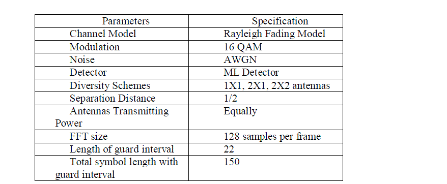
Keywords
|
| Alamouti STBC, MIMO-OFDM, FFT, 16-QAM, QPSK, MATLAB. |
INTRODUCTION
|
| Wireless communication systems are playing crucial role in this world. Initially, wireless systems were mainly designed to support voice. Later these are used to transfer the data, they gain popularity because of their ease of use and mobility .All wireless technology face the challenges of signal fading, multipath, increasing interference and limited spectrum. Orthogonal Frequency Division Multiplexing (OFDM) plays a crucial role and reduce receiver complexity in wireless broadband systems but in this case synchronization and channel estimation are very important, and it is replaced by Multiple Input Multiple output-Orthogonal Frequency Division Multiplexing (MIMO-OFDM) which is a multi-user OFDM that allows multiple accesses that scheme that combines TDM and FDM on the same channel, widely for the next generation wireless communication systems such as WLAN,WMAN, WiMAX and 3G-LTE standard in order to accommodate many users in the same channel at the same time. The use of MIMO technology in combination with OFDM, i.e., MIMO-OFDM is therefore seems to be an attractive solution for future broadband wireless systems. But this MIMO system having fast framing rate of the order of 1–2 μs will be polluted by ISI when operational in an environment having a typical time delay Spread of 200 μs |
| Thus an ISI value of 200/2 = 100 is an undesirable multi-path effect for the real MIMO system. Therefore MIMO cannot achieve zero ISI and hence cannot be utilized alone. OFDM based multi-carrier approach may be enabler for the MIMO broadband operation So the fast frames are slowed down first and converted to several slow sub frames and modulated to multiple carriers of OFDM. OFDM-MIMO is, therefore, useful technology which can be explored both for communication and remote sensing (radar). MIMO concept was first introduced by Jack Winters in 1987 for two basic communication systems. The first was for communication between multiple mobiles and a base station with multiple antennas and the second for communication between two mobiles each with multiple antennas. |
| To improve the BER performance of a wireless transmission system in which the channel quality fluctuates, it suggested that the receiver should be provided with multiple received signals generated by the same underlying data. These suggestions are referred as diversity which exists in different forms such as temporal diversity, frequency diversity and antenna diversity. Temporal diversity includes channel coding in conjunction with time interleaving which involves redundancy in time domain. Frequency diversity means transmission of different frequencies which provides redundancy in frequency domain. Antenna diversity can be viewed as redundancy in spatial domain and implemented by using multiple antennas at both transmit side (base station) and the receive side (mobile units). |
| provides redundancy in frequency domain. Antenna diversity can be viewed as redundancy in spatial domain and implemented by using multiple antennas at both transmit side (base station) and the receive side (mobile units). |
RELATED WORK
|
| In 2009, Jiang Xuehua et al, [10] proposes a model of MIMO-OFDM. The system is composed of transmitter, channel, receiver and so on. Space time coding is done in the transmitter. Analysis is done by adding more antennas at the receiver side using MATLAB simulation tool. Experiment results show that the MIMO-OFDM wireless communication system has better performance when there are more antennas at receiver side but with the increase of the carier number, the system performance will reduce because of the interference between sub-carriers. |
| In 2010, Veranna et al, [6] uses Space Time Frequency coded communication system using diversity schemes like MIMO and MISO and their performance is evaluated over a fading channel having inherent noise. MATLAB 7.0.1 is used as simulation tool to compare the performance of MISO and MIMO technique. MIMO scheme performed better than MISO in comparison of BER vs SNR. Paper also compares the channel capacity obtained by various MIMO diversities as function of signal to noise (SNR) ratio and proves that as diversity increases the channel capacity increase. |
| In 2013, M. Vani Divyatha et al, [5] discuss the design of MIMO-OFDM for wireless broadband communication. MIMO_OFDM is considered for different modulation schemes which are used to encode and decode the data stream in wireless communication over AWGN channel for unknown transmitter and known receiver. MIMO detection methods are investigated on VBLAST architecture. At the end of the paper, there is a slight increase in the spectral efficiency by using VBLAST architecture. |
| In 2013, Jitendra Kumar Daksh et al, [3] discusses several aspects in the direction of Space-time coding in MIMOOFDM systems with multiple antennas. In this paper two space time coding techniques are discussed and brief introduction can be seen. Also this paper gives the recent work of space time coding techniques and analysis of related work. Two prevailing space-time coding techniques are Space Time Block Codes (STBC) and Space Time Trellis Codes (STTC). STBC provide diversity gain, with very low decoding complexity, whereas STTC provide both diversity and coding gain at the cost of higher decoding complexity. STBC must be concatenated with an outer code to provide coding gain. Concatenating STBC with Trellis Coded Modulation (TCM) creates a bandwidth efficient system with coding gain. This paper discusses about previous results in the direction of their survey. This result in the fact of increasing the number of antenna has better transmission performance. And also increasing the states reduces the SNR. |
| In 2013, Niharika Sethy et al, [8] gives the BER analysis of BPSK signal in MIMO and MIMO-OFDM using MATLAB simulink. . MIMO System is used to achieve full diversity using OSTBC encoder, to overcome fading effect of channel. By using OFDM, ISI can be reduced with higher data rate and higher spectral efficiency. Simulation is done for MIMO-OFDM (2X2) system in Rayleigh and Rician Channel. The BER performance of Rician channel is better than Rayleigh Channel. But the BER performance of Rayleigh Channel in MIMO system is much better than that of Rician channel. Here it is observed that Here we can observe that the BER performance of MIMO system is better than that of MIMO OFDM system. But as comparison to MIMO system the MIMO OFDM is more spectrally efficient. |
| In 2010, A Khatoon et al, [11] analyzes the symbol error performance of a wireless communication system using diversity combining scheme in Rayleigh fading channels. The performance of the system is compared using Alamouti scheme and maximal-ratio receiver combining (MRRC) scheme. The probability of error of SISO system and Alamouti scheme (2X1, 2X2 ) and MRRC scheme (1X2, 1X4) in Rayleigh fading channels is investigated. For more SNR the STBC outperforms MRRC. Exact closed-form expressions are derived for average symbol-error-probability (SEP) for both M-PSK and M-QAM modulation schemes. The numerical results show exact match with Monte Carlo simulation. |
SPACE TIME BLOCK CODING
|
| Space-Time Block Coding (STBC) is based on the scheme presented by Alamouti. This scheme provides transmit and receive diversity to MIMO system (Fig.4). This figure shows Maximal Ratio Receive Combining (MRRC) scheme. [6- 8] |
| Three main functions of Alamouti scheme can be defined as: |
| Encoding and deciding transmission sequence information |
| Symbols at the transmitter |
| Combining signals with noise at the receiver |
| Maximum likelihood detection |
| Suppose we have two antennas at both the transmitter and receiver then let s1 be the symbol transmitted from antenna 1 and s2 be the symbol transmitted from antenna 2 at time period T. |
| –s2* will be transmitted from antenna 1 and s1* is transmitted from antenna 2 at T+1 time period, where (*) denotes the conjugate of a number. .In STBC encoder input symbols are divided into 2 groups. {s1, s2} Symbols of each group will be transmitted as shown in Figure 1. |

Fig.1 The system equation becomes |
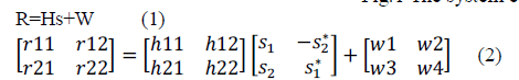 |
| The above matrix shows that the two rows/columns of STBC matrix, that are orthogonal to each other. r11 and r12 denotes receiver 1 and r21 and r22 denotes receiver 2. H is the channel matrix and W is the white Gaussian noise. The s1 and s2 symbols along with their conjugates are placed on OFDM subcarrier for further transmission through channel. [4, 9] |
EXPERIMENTAL DESIGN
|
| In the present study block scheme of a STBC with OFDM is designed. As shown in Fig, block diagram represents the whole system model. The block system is divided into 3 main sections namely the Transmitter, Channel and the Receiver. |
 |
| A. Transmitter |
| In this paper two kinds of source data are used, either the randomly produced data or an image file. While random data is ideal to test the channel impact to the BER performance and signal constellation, image file give us an intuitive impression and comparison for different channels. |
| The data is generated from a real time input image/random signal. The transmission is completed block wise. Furthermore, the size of the data generated is depends on the block size. The 16 QAM modulation schemes are used to map the bits to symbols. The generated data is passed on to the next stage, Space Time Encoder or MIMO encoder, the Space Time Encoder stage converts one single input data stream into multiple output data streams. How the output streams are formatted depends on the type of MIMO method employed. Here we make use of the OFDM sub carriers. This data is then fed to the channel.. In most of the mobile or cellular systems, the height of the mobile antenna may be smaller than the surrounding structures. Thus, the existence of a direct or line-o-sight path between the transmitter and the receiver is highly unlikely. In such a case, propagation is mainly due to reflection and scattering from the buildings and by diffraction over and/or around them. So, in practice, the transmitted signal arrives at the receiver via several paths with different time delays creating a multi-path situation. At the receiver, these multi-path waves with randomly distributed amplitudes and phases combine to give a resultant signal that fluctuates in time and space. Therefore, a receiver at one location may have a signal that is much different from the signal at another location, only a short distance away, because of the change in the phase relationship among the incoming radio waves. This causes significant fluctuations in the signal amplitude. This phenomenon of random fluctuations in the received signal level is termed as fading [4-5]. Fading can be classified as frequency-flat and frequency-selective. If the signal bandwidth is lesser than the Coherence bandwidth, the fading is known as frequency-flat. If signal bandwidth is greater than the Coherence bandwidth of the channel, the fading is frequency-selective. MIMO mitigates the effect of flat fading but not the frequency selective fading but by using the OFDM modulation in congestion with the MIMO, frequency selective fading can be converted to flat fading by using N subcarriers in the OFDM technology which makes the signal bandwidth lesser than the coherence bandwidth. |
| OFDM signals are generated digitally and the signal consists of a sum of subcarriers that are modulated using BPSK or QPSK or QAM. The relationship between all the carriers must be controlled to maintain the orthogonality of the carriers [6]. After modulating the input data digitally, the resulting spectrum is converted back to its time domain using Inverse Fourier Transform (IFFT). The IFFT converts a number of complex data points, of length power of 2, into the time domain signal of the same number of points. Fig2. shows the block diagram of OFDM transceiver and each block is discussed in the following sub sections. |
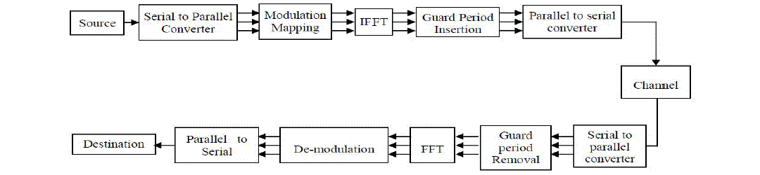
Fig.2 Block diagram of OFDM Transceiver |
| Serial to Parallel Conversion: In OFDM each symbol typically transmits 40-4000bits, so a serial to parallel conversion is needed to convert the input data to be transmitted in each OFDM symbol. The data allocated to each symbol depends on the modulation scheme and the number of subcarriers. For example, for a subcarrier modulation of QPSK each subcarrier carries 2 bits, and so for a transmission using 100 subcarriers, the number of bits per symbol would be 400. |
| Modulation Schemes: The modulation scheme is a mapping of data words to a real (In phase) and imaginary (Quadrature) constellation, also known as an IQ constellation. It is also useful to define number of bits per symbol. For example if 16 QAM is used then performing Log2 (M) gives 4 bits per symbol. |
| IFFT: An IFFT is used to convert the signal to the time domain allowing it to be transmitted [5]. The IFFT drastically reduce the amount of calculations by exploiting the regularity of the operations in IDFT. Using the radix-2 algorithm, an N-point IFFT requires only (N/2) log2N complex multiplications. |
| Guard Period: One of the most important advantages of OFDM is its robust to multipath delay spread, and that is achieved by dividing the input stream in Ns subcarrier, the symbol duration is made Ns times smaller, which also reduces the relative multipath delay spread, relative to the symbol time, by the same factor. Guard time is introduced to each symbol to eliminate ISI. The component from one symbol cannot interfere with the next symbol. Guard time consists of no signal at all. In this case, we will have another problem which is Inter Carrier Interference (ICI). ICI is the cross talk between different subcarriers, which mean they are no longer orthogonal. To eliminate ICI, OFDM symbol must be cyclically extended in the guard time. This ensures that the delayed replicas of the OFDM symbol always have an integer number of cycles with in FFT interval, as long as the delay is smaller than the guard time. As a result, all multipath signals with delay smaller than the guard time cannot cause ICI. |
| B. Channel |
| Based on the fading distribution, variety of fading models is there, which are well-known in wireless communication system as a wireless communication channel. We are considering Rayleigh fading model.Rayleigh fading is statistical channel model for the representation of the effect of multi-path propagation environment over transmission symbols or radio signals. Now, when the transmitted signal passed through the channel will vary randomly or fade according to the Rayleigh distribution then that channel termed as RAYLEIGH channel. Rayleigh fading is mostly applicable only when there is no Line-Of-Sight between transmitter and receiver. So, if s(t) is transmitted symbol then the received symbol is given as |
| `R(t)=s(t)*h(t)+η(t) (3) |
| Here R(t) is distributed by using Rayleigh distribution function. |
| Where η(t) is the Additive White Gaussian Noise (AWGN). |
| C. Receiver |
| The demodulation of an OFDM signal is performed exactly the same manner. In the receiver, FFT is used to estimate the amplitude and phase of each subcarrier. The FFT performs the same operation as the matched receiver for the single carrier transmission, except for a bank of subcarriers. The first task performed at the receiver (in simulation) is removal of cyclic prefix. This eliminates the inter symbol interference (ISI). The data is then passed through the serial to parallel converter and then passed to the FFT for frequency domain transformation. The signal was found distorted by the channel, however, to reconstruct the original signal, the information on how these channels are acted on the transmitted signal need to be obtained to mitigate its effect. This is called equalization. In OFDM system, this is done by channel estimation and interpolation, and reverse process (including decoding) is executed to obtain the original data bits. |
SIMULATION RESULTS AND DISCUSSION
|
| The real time performance of the transmitted images through SISO-OFDM, MISO-OFDM and 2x2 MIMO-OFDM systems are presented in this section. The performance of these systems is evaluated with reference to BER v/s SNR and quality of the output image. For this study I/P parameter is real time 8 bit gray scale image as shown in Fig3. |
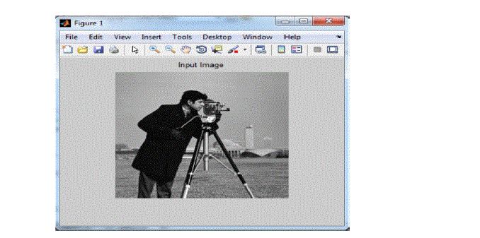
Fig.3 Input Image |
| SNR versus BER graphs are plotted for 16 QAM with convolution encoder rate is ½ for the SISO system. |
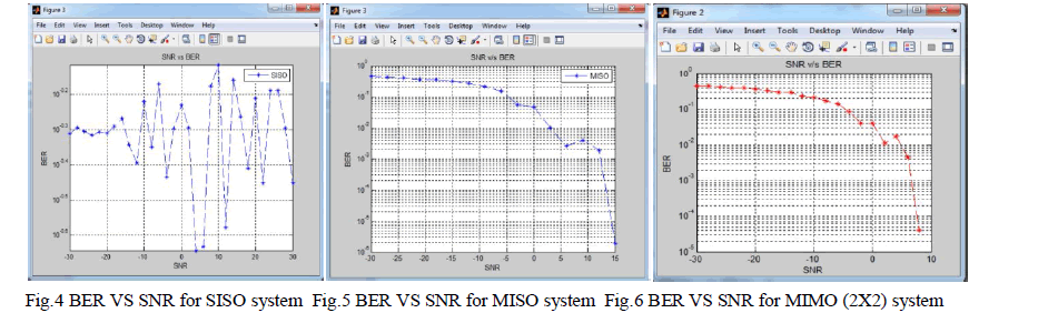 |
| Fig4, Fig5, and Fig6, shows BER graph of SISO-OFDM, MISO-OFDM and MIMO-OFDM system respectively. It can be observed from these figures that at 10 SNR, BER of MIMO-OFDM system is significantly lower (10-4.8) as compare to MISO-OFDM system (10-2.6) and SISO-OFDM system (10-0.2). |
| The same can be confirmed by the output images of SISO-OFDM, MISO OFDM and MIMO OFDM systems as shown in Fig7, Fig8 and Fig9, respectively. |
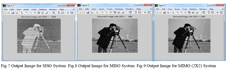 |
| The reason behind getting better image quality using MIMO-OFDM system is apparently the low BER. The increasing number of transmit and receive antennas from 1 to 2 leads to improve the signal quality by reducing the fading effect. Therefore, with MIMO-OFDM system reliable communication is possible at low values of SNR |
CONCLUSION
|
| This paper demonstrates the results of 1X1 SISO-OFDM, 2X1 MISO-OFDM and 2X2 MIMO-OFDM system with real time input image. The results shows that BER is significantly reduced in MIMO-OFDM system as compare to MISOOFDM system and SISO-OFDM system. These results show that adding one antenna at the receiver side can improve the performance of the system. The MIMO-OFDM model demonstrated in this study can be used for real time data transmissions such as multimedia and high speed internet applications especially in low SNR areas. |
References
|
- M. Chethan Kumar, Sanket Dessai, “Design, Implementation And Optimization of 4x4 Mimo-Ofdm Transmitter for CommunicationSystems”, SASTECH journal, Volume 12, Issue 2, September 2013.
- R. Suresh Babu, M. Suganthi and K. Ramasamy, “Ber Performance Comparison Of Multiple Antenna Using Space Time Block Coded OfdmSystem In Multipath Fading Environment”, ICTACT Journal On Communication Technology, March 2011, Vol: 02, Issue: 01.
- Jitendra Kumar Daksh, Ravi Mohan, Sumit Sharma, “Performance Analysis with Space-time coding in MIMO-OFDM Systems with MultipleAntennas”, International Journal of Advanced Computer Research (ISSN (print):2249-7277 ISSN (online):2277-7970) Volume-3 Number-2Issue-10 June-2013.
- Shubhangi Chaudhary, A.J. Patil, “Performance Analysis Of Mimo-Space Time Block Coding With Different Modulation Techniques”, IctactJournal On Communication Technology, March 2012, Volume: 03, Issue: 01
- M. Vani Divyatha, B. Siva Reddy, “ Design and BER Performance of MIMO-OFDM for Wireless Broadband Communications”, InternationalJournal of Modern Engineering Research (IJMER), Vol.3, Issue.3, May-June. 2013 pp-1382-1385 ISSN: 2249-6645.
- R Veeranna Sake Pothalaiah Prof. K Ashok Babu, “Implementation Of Mimo Ofdm Stf Coding Framework For Wireless CommunicationSystem”, International Journal of Engineering Science and Technology Vol. 2 (12), 2010, 7423-7436.
- M. N. Rindani , A. A. Bavarva, “Ber Performance Comparision of 4x4 Extended Alamouti Scheme For Different Fading Channels”,International Journal of Advanced Research in Electrical, Electronics and Instrumentation Engineering, Vol. 2, Issue 3, March 2013.
- Niharika Sethy, Subhakanta Swain, “BER analysis of MIMO-OFDM system in different fading channel”, IJAIEM, Volume 2, Issue 4, April2013P. K. Visscher, “How Self-Organization Evolves,” Nature, vol. 421, pp. 799–800 Feb.2003.
- Archana Ogale, Shubhangi Chaoudhary, A. J. Patil, “Performance Evaluation of MIMO-OFDM System using Matlab® Simulink With RealTime Image Input”, 978-1-4673-5999-3/13/$31.00 ©2013 IEEE.
- Jiang Xuehua, Chen Peijiang, “Study and Implementation of MIMO-OFDM System Based on Matlab”, International Conference onInformation Technology and Computer Science, 2009.
- A. Khatoon, M. S. Rahman, “ Symbol Error Performance Analysis and Comparison between Alamouti and MRRC Diversity CombiningScheme for Wireless Communication”, Journal of Scientific Research, J. Sci. Res. 2 (1), pp-54-66, 2010.
|