ISSN ONLINE(2278-8875) PRINT (2320-3765)
ISSN ONLINE(2278-8875) PRINT (2320-3765)
V.Kulandaivel1, S.Shalini2
|
| Related article at Pubmed, Scholar Google |
Visit for more related articles at International Journal of Advanced Research in Electrical, Electronics and Instrumentation Engineering
This paper reduces the number of fuzzy sets of membership functions. A self-tuning fuzzy logic controller with modified rule base is used to reduce the membership functions. Conventionally, PI- like fuzzy controller and self-tuning fuzzy controller mechanism is used to reduce the fuzzy membership functions. In fuzzy logic controller scaling factors plays a major role. The output scaling factor is tuned by a gain updating factor, which is derived from fuzzy logic reasoning, by using plant error and change in error ratio as the input variables. By using selftuning fuzzy logic controller with modified rule base is reduce the complexity of the controller without losing system performance and stability.
Keywords |
| Membership Function (MF), Scaling Factor (SF), Switched Reluctance Motor (SRM), PI-like Fuzzy Controller (PIFC), Self-Tuning PI-like Fuzzy Controller (STFC). |
I.INTRODUCTION |
| The SRM is a type of synchronous machine.SRM is electro-magnetic and electro-dynamic equipment which convert electrical energy into mechanical energy. It provides high reliability, wide-speed range at constant power, low manufacturing cost, fast dynamic response, ruggedness and fault tolerance. It is used in variable applications like pumps, fans, washing machines, vacuum cleaners, robotics control applications, future automobile applications etc. Fuzzy set have a smooth boundary. It allows a member to belong to a set to some partial degree. The fuzzy controller is an artificial decision maker that operates in a closed loop system in a real time. The main part of fuzzy controller we focus on for design rule base. The rules are used to represent how to control the plant. The fuzzy rule is represented by a sequence of the form IFTHEN, which includes both input and feedback if a closed-loop control system is applied. |
| The IF part is mainly used to capture knowledge by using the elastic conditions, and the THEN part can be utilized to give the conclusion or output in linguistic variable form. This IF-THEN rule is widely used by the fuzzy inference system to compute the degree to which the input data matches the condition of a rule. The performance of the fuzzy logic controller are scaling factor (SF) tuning, rule base modification, inference mechanism improvement and membership function redefinition mechanism and shifting. Scaling factor (SF) tuning is most using approach among them. The fuzzy logic controllers contain a set of parameters that can be altered on line in order to modify the controller performance. These include the scaling factors for each controller variable, the membership functions of the linguistic terms and the rules. The fuzzy model encapsulates the nonlinear function relating the SRM rotor position to the flux linkage and current. The model is then utilized during the operation of the sensorless rotor position estimation scheme to calculate the rotor position from measured values of flux linkage and current. |
| By using self-tuning fuzzy logic controller the output scaling factor can be adjusted according to their corresponding current states of the controlled processes. By changing membership functions or scaling factors or both of them is tunes in already working condition of fuzzy logic controller is called self-tuning fuzzy logic controller. The main advantage of self-tuning is greater control capability, robust, improve flexibility. |
II.PHASE CONVERTER |
| The phase converter was used for controlling the switched reluctance motor. It contains two power semiconductor switching devices and two diodes which shown in fig 1. For high speed operation it is required to see that the stored energy can be fed back to the mains within the available period. The advantage of these converter are the other phases are independently controlled by each phase, the energy from the off going phase is feedback to the source, which results in utilization of the energy and the converter is able to free wheel the energy during the chopping period at low speeds which helps to reduce the switching frequency and thus the switching losses of the converter. The phase winding A is connected to the dc supply through power semiconductor devices T1 and T2. Depending upon the rotor position, when the phase winding A is to be energized the devices T1 and T2 are turned ON. When the phase winding A is to be disconnected from the supply the device T1 and T2 are turned off. The stored energy in the phase winding A tends to maintain the current in the same direction. This current passes from the winding through D1 and D2 to the supply. Thus the stored energy is fed back to main. |
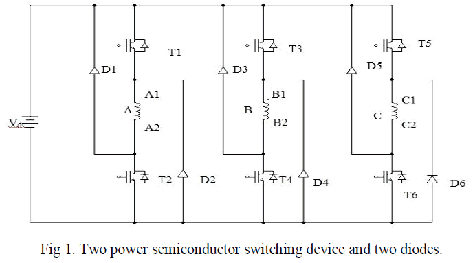 |
| Similarly phase winding B & C are also switched on to the supply and switched off from the supply in a cyclic manner. Usually the upper devices T1, T3 and T5 are turned on and off from the signals obtained from the rotor position sensor. The duration of conduction or angle of conduction can θ be controlled by using suitable control circuit. The lower devices T2, T3 and T5 are turned on and off from the signal. The current in the phase winding is the result of logically ANDing of the rotor position sensor and chopping frequency. As a result it is possible to vary the effective phase current from a very low value to a high value. For varying the current the following methods are available. |
| 1. By varying the duty cycle of the chopper. |
| 2. By varying the conduction angle of the devices.` |
III.MODIFIED RULE BASE |
| It is the combination of rule base of controller output Δu and gain updating factor α. The modified rule base reduces the complexity of the controller by reducing the number of control rules. |
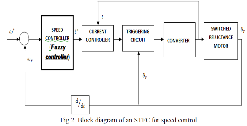 |
| The speed control of switched reluctance motor using self-tuning fuzzy logic controller which shown in fig2.The controller inputs are e, Δe and the output is Δu are the membership functions. The membership functions are defined on domain [-1, 1]. The NB, NS, ZE, PS, PB are negative big, negative small, zero, positive small, positive big respectively. The fig 3. shows the fuzzy membership function. |
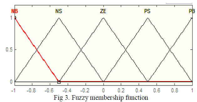 |
| The simplest membership functions are formed using straight lines which triangular membership function, and it has the function name ‘trimf’. It’s nothing more than a collection of three points forming a triangle. |
| There is no fixed, unique, and universal rule or criterion for selecting a membership function for a particular “fuzzy subset” in general a correct and good membership function is determined by the user based on his scientific knowledge, working experience, and actual need for the particular application in question. The types of Membership functions are Triangular, Trapezoidal, Gaussian, Sigmoidal Membership functions. |
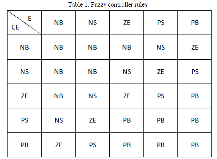 |
| The rules consist of 25 IF-THEN rules. The E is the error and CE is the rate of the error change. The fuzzy rules are |
| 1. If speed error e is NB and the change in speed error ec is NB then speed variation is NB which is shown in table 1. |
| 2. If speed error e is PS and the change in speed error ec is NB then speed variation is NS. |
IV. RESULT AND DISCUSSION |
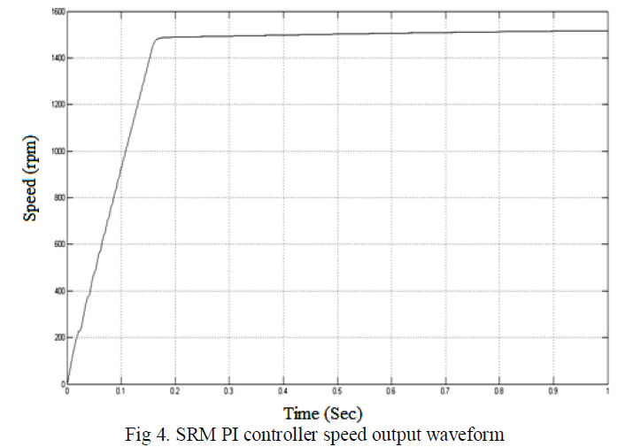
| The fig 4. Shows the speed output waveform for switched reluctance motor using PI controller. Here the set point speed value is 1500 RPM the desired output speed is attained after 0.16 sec. |
 |
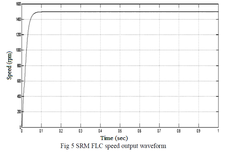
| The fig 5. Shows for switched reluctance motor using fuzzy logic controller speed output waveform. Here the set point speed value is 1500 RPM the desired output speed is attained after 0.05 sec. |
 |
| The below table is representing the conventional PI controller and fuzzy self-tuning controller according to the tuning and settling time of the controller the desired speed is obtained. The self–tuning fuzzy logic controller performance is better than conventional PI controller. |
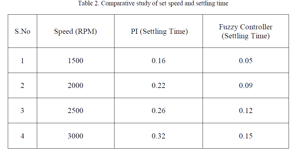 |
| The table 2. shows the various set speed and settling time in PI controller and fuzzy logic speed controller. The fuzzy logic controller settling time is very low compared to PI controller. |
VI.CONCLUSION |
| By reducing the number of fuzzy sets of the membership functions to simplify the complexity of the controller without losing the system performance and stability. The output scaling factor is tuned by a gain updating factor, which is derived from fuzzy logic reasoning, by using plant error and change in error ratio as the input variables. The modified rule base design system is robust to load disturbance. The self- tuning fuzzy logic controller has better dynamic response curve, small overshoot, small steady state error, high steady precision, and shorter response time compared to the PI controller. |
References |
|