International Journal of Advanced Research in Electrical, Electronics and Instrumentation Engineering
ISSN ONLINE(2278-8875) PRINT (2320-3765)
ISSN ONLINE(2278-8875) PRINT (2320-3765)
K. Satyapriya1 (M.Tech), Yugandhar Dasari2
|
| Related article at Pubmed, Scholar Google |
Visit for more related articles at International Journal of Advanced Research in Electrical, Electronics and Instrumentation Engineering
Speech coding has been major issue in the area of digital speech processing. Speech coding is the act of transforming the speech signal in a more compact form, which can be transmitted with few numbers of binary digits. It not possible to access unlimited bandwidth of a channel each time we send a signal across it which leads to code and compress speech signals. Speech compression is required in the areas of long distance communication, high-quality speech storage, and message encryption. For example in digital cellular technology many users need to share the same frequency bandwidth. Utilizing speech compression makes it possible for more users to share the available system. Another example where speech compression is needed in digital voice storage for a fixed amount of available memory compression makes it possible to store longer messages. Speech coding is a lossy type of coding, which means that the output signal does not exactly sound like the input. Linear Predictive coding, Waveform Coding and sub band coding techniques are used to transmit the speech from one place to another. The above mentioned three coding techniques are implemented to check their performance measures like compression ratio and speech audible quality.
Keywords |
| Linear Predictive Coding (LPC), Wave form coding, Sub band coding |
I. INTRODUCTION |
| Speech coding is the process of representing a voice signal for efficient transmission or storage. These codes will be sent over both band limited wired and wireless channels. The goal of speech coding is to represent the samples of a speech signal in a compact form which takes less code symbols without degrading the quality of the speech signal. Speech coding is very important in Cellular and Mobile Communication. It is also used in Voice over internet protocol (VOIP), Videoconferencing, electronic toys, archiving, Digital simultaneous voice and data (DSVD), numerous computer based gaming and Multimedia applications. In addition, most of the speech applications require minimum coding delay in order to avoid hindering the flow of the speech conversation because of long coding delays |
| A speech coder is one which converts a digitized speech signal into the coded representation and transmits it in a form of frames. At the receiving end, the speech decoder receives the coded frames and synthesizes reconstructed speech signal. The speech coders mainly differ in bit-rate, delay, complexity and perceptual quality of the synthesized signal. There are two types of coding techniques like Narrowband and Wideband speech coding. Narrowband speech coding is the coding of speech signals bandwidth between 300 to 3400 Hz with 8KHz sampling rate whereas, Wideband speech coding is the coding of speech signals bandwidth less than 50 to 7000 Hz with sampling rate 14- 16KHz sampling rate. In the recent days, there is an increase in demand for wideband speech coding techniques in applications like video conferencing. |
| The objective of speech coding is to compress the speech signal by reducing the number of bits per sample but it should not lose the quality of the speech. The decoded speech should be audibly indistinguishable from the original speech signal. Specifically speech coding methods achieve the following gains: |
| Bit rate reduction or equivalently the bandwidth. Bit rate reduction leads to reduction in memory requirements which decreases in a proportionate manner with respect to bit-rate. |
| Bit rate reduction leads to reduction in the transmission power required, since compressed speech has less number of bits per second to transmit. |
| Immunity to noise, some of the saved bits per sample can be used as protective error control bits to the speech parameters. |
| Speech coding techniques are mainly two types those are 1.Lossless and 2.lossy coding methods. The lossy coding technique have the reconstructed speech signal perceptually different from the original speech signal whereas the lossless coding technique, the reconstructed signal at the decoder end has exactly the same shape as the input speech signal. Mostly the speech coding techniques are based on the lossy coding technique because it removes the information which is irrelevant from the perceptual quality point of view. |
| Speech coders are classified based on the bit-rate at which they produce output with reasonable quality and on the type of coding techniques used for coding the speech signal. |
 |
| There are different speech coder types In the Table-1 the bit-rates, algorithmic complexity and four standardized applications of the four general classes of coders described |
| Linear Prediction Coders (LPCs), assume that the output speech signal is linear time invariant (LTI) model of speech produced. We assumed that model`s transfer function is all-pole system. The excitation function is a quasi periodic signal which is constructed from discrete pulses (1-8 per pitch period), pseudorandom noise, or combination of the two. The excitation signal generated at the receiver is based on transmitted pitch period and voicing information, then the system is designated as an LPC vocoder. The extra information provided about the spectral shape of the excitation signal is called LPC- Vocoder, that have been adopted as coder standards between 2.0 and 4.8 kbps.On the other hand, LPC-based analysis-by-synthesis coders (LPC-AS) take a large set of candidate excitations and chooses the best one out of those . These LPC-AS coders are used in most standards between 4.8 and 16 kbps. In the waveform coding concept the coded speech signal waveform is same as applied speech signal waveform, without considering the nature of human speech production and speech perception. These coders are high-bit-rate coders (above 16kbps). Subband coders are frequency-domain coders that attempt to parameterize the speech signal in terms of spectral properties in different frequency bands. These coders are less widely used than LPC-based coders. |
II. LINEAR PREDICTIVE CODING |
| Linear Predictive Coding (LPC), a powerful, good quality, low bit rate speech analysis technique for encoding a speech signal. The source filter model used in LPC is also known as the linear predictive coding model. It has two main components LPC analysis (encoding) and LPC synthesis (decoding). The goal of the LPC analysis is to estimate whether the speech signal is voiced or unvoiced, to find the pitch of each frame and to the parameters needed to build the source filter model. These parameters are transmitted to the receiver will carry out LPC synthesis using the received parameters. |
| The speech signal is filtered to more than one half of the system sampling frequency and then it performs A/D conversion. The LPC coding and decoding procedure explained in detail in the following steps. |
| Linear Predictive Coding: |
| Step 1: Read the speech signal in digital format. |
| Step 2: Choose the LPC coefficient length as 10 and frame time duration of 30ms so that frame length becomes 331. |
| Step 3: Speech signal is divided into frames and each frame will be processed is given below. |
| Step 4: Pre-emphasis each frame before doing further processing. |
| Step 5: Find Filter response to calculate magnitude sum function. Calculate zero crossings and pitch period. |
| Step 6: Threshold values are set for msf, zero crossings and pitch period. |
| Step 7: Check whether the frame is voiced or not based on step 6. |
| Step 8: LPC-10 coefficients, gain and pitch plot are calculated based on the frame is voiced or unvoiced. |
| Step 9: Now the values obtained in step 8 are transmitted by using the encoding procedures. |
| Step 10: At the receiver signal is received and it is decoded to the required form |
| Step 11: The original and received signal is verified. |
| Linear Predictive Coding (LPC) Of Speech: |
| For speech analysis and synthesis a linear predictive coding (LPC) method is based on modeling the vocal tract as a linear all-Pole (IIR) filter, whose system transfer function is |
 |
| Where ‘ ’ is the number of poles, are the parameters that determine the poles and is the filter Gain,. There are two excitation functions to model voiced and unvoiced speech sounds. The output of the random noise generator will generate unvoiced sound by exciting the all-pole filter. On the other hand, by a periodic impulse train a voiced speech is generated by exciting the all pole filter model. |
 |
| The fundamental difference between these two voiced and unvoiced speech sounds comes from the way how they are produced. The vocal cords vibrations produce these voiced sounds. The vocal cords vibrate at the rate which determines the pitch of the sound whereas; unvoiced sounds do not depend on the vibration of the vocal cords. By the constriction of vocal tracts the unvoiced sounds are produced. The constrictions of the vocal tract force air out to produce the unvoiced sounds when the vocal tract is open |
| Given a short segment of a speech signal, let us say about 20 ms or 160 samples at a sampling rate of 8 KHz, the speech encoder at the transmitter must determine the proper excitation function, the pitch period for voiced speech, the gain, and the coefficients ap[k].The block diagram below describes the encoder/decoder for the Linear Predictive |
| Coding. The parameters of the model are determined adaptively from the data and modeled into a binary sequence and transmitted to the receiver. At the receiver end, the model and excitation signal will synthesize the speech signal. |
| The parameters of the all-pole filter model are determined from the speech samples by means of a linear prediction. The output of the Linear Prediction filter is |
| The error between the observed sample s(n) and the predicted value s(n) is |
| by minimizing the sum of the squared error to determine the pole parameters ap(k) of the model. The result of differentiating the sum with respect to every parameter and equation that results to zero, |
 |
| where m=1,2,….p |
 |
 |
 |
III. WAVEFORM CODING |
| Waveform coding is the simplest technique for speech coding. Waveform coders analyze code and reconstruct original signal, sample by sample. Waveform coders are used to reproduce the exact shape of the speech signal waveform, without considering nature of human speech production and delivering system. Waveform coders are useful in applications that require successful coding of both speech and non-speech signals. In the public switched telephone network (PSTN), for example, successful transmission of modem and fax signaling tones, and switching signals is nearly as important as the successful transmission of speech. The most commonly used waveform coding algorithms are uniform 16-bit PCM, companded 8-bit PCM and ADPCM. |
| Waveform coding is explored in both time and frequency domain. Time domain waveform coding exploits signal redundancies like periodicity, slow varying intensity etc. and spectral (frequency) domain coding exploits nonuniform distribution of speech information across full frequency band. Pulse Code Modulation(PCM), Differential Pulse Code Modulation(DPCM), Delta Modulation(DM) are some of the popular time domain waveform coding techniques and Transform Coding(TC), Sub Band Coding(SBC) are few spectral domain waveform coding techniques. |
| 3.1 PCM: |
| PCM is the best known waveform coding technique which quantizes and encode every sample of speech value to a finite number of bits. In PCM coding samples of the speech, where amplitude can take infinite possible values, are compared with finite set of amplitudes and closed among these is chosen to represent actual amplitude. The chosen discrete value is assigned a binary codeword for digitization which gets used for transmission or storage of speech. PCM is often used when resource such as transmission bandwidth or storage space is not a limitation. In a simple quantizer known as uniform quantize the spacing between discrete amplitude levels is kept same. |
| Pulse code modulation (PCM) is the name given to memory less coding algorithms that quantizes each sample |
| of s(n) by using the same reconstruction levels ^ s ,k =0, . . . ,m, . . . ,K, regardless of the values of previous samples. The reconstructed signal sˆ(n) is given by |
 |
| 3.2 Uniform PCM: |
| Uniform PCM is the quantization algorithm in which the reconstruction levels are uniformly distributed between Smax and Smin. The advantage of uniform PCM the quantization error power does not depend on signal power; high-power signals are quantized with the same resolution as low-power signals. In digital audio 16-bit uniform PCM is a standard coding scheme. The error power and SNR of a uniform PCM coder vary with bit rate in a simple fashion. |
IV. SPEECH CODING FUNDAMENTALS AND APPLICATIONS |
| 4.1 Companded PCM: |
 |
| 4.2 Waveform Coding: |
| Step 1: Read the speech signal in digital format. |
| Step 2: Determine “mu” value and “Number of bits” and compress the speech signal using mulaw companding using expression (13) |
| Step3: Now the signal is transmitted |
| Step 4: At the receiver signal is received and it is expanded using mu law companding |
| Step 5: The original and received signal is verified. |
| 4.3 Sub-band Coding: |
| Sub-band coding is an effective method to achieve data compression in speech signals. Sub-band coding is decomposing the source signal into constituent parts and decoding the parts separately. A system that isolates a constituent part corresponding to certain frequency is called a filter. If it isolates the low frequency components, it is called a low-pass filter. If it isolates the high frequency components, it is called a high-pass filter Similarly, we have band-pass filter. Generally, a filter can be called as a Sub-band filter if it isolates a number of bands simultaneously. The most frequently used filter banks in Sub-band coding consists a cascade of stages, where each stage consists of a low-pass filter and a high-pass filter. |
| The three major components of Sub-band coding scheme is |
| The Analysis and Synthesis filters |
| The Bit allocation scheme |
| The Encoding scheme |
| If we apply the filter bank scheme, the source output is passed through the filters. The filter bank covers the range of frequencies that design the source output. The pass band of each filter specifies each set of frequencies that can pass through. Now decimation process starts, the outputs of the sampled filters are sub sampled this reduces the number of samples. The justification for the sub sampling is the Nyquist rule and its extension justifies the down sampling. The amount of decimation depends on the ratio of the bandwidth of the filter output to the filter input. Then the signal is given to the encoder where the decimated output is encoded using one of several encoding schemes, including ADPCM, PCM, and vector quantization. |
| The speech signal thus obtained is Quantized and coded by the selection of the compression scheme and by the allocation of bits between the sub-bands. This bit allocation procedure significantly impacts quality of the final reconstruction. Different sub-bands have different amount of information. This signal is transmitted through the channel. |
 |
 |
| The transmitted signal is received and synthesized. The quantized and coded coefficients are used to reconstruct a representation of the original signal at the decoder. The encoded samples from each Sub band are decoded and up sampled. The bank of reconstruction filters will give different outputs which are combined to form the final reconstructed output signal. The Sub-band coding algorithms have applications in speech coding, audio coding and image compression. |
| Sub Band Coding: |
| Step 1: Read the speech signal in digital format. |
| Step 2: Speech signal is decomposed to two levels using wavelet analysis filters. |
| Step 3: Now these wavelet coefficients are partially transmitted to achieve the compression by identifying the quality of the received signal. |
| Step 4: At the receiver, Speech signal is reconstructed using wavelet synthesis filters. |
| Step 5: The original and received signal is verified. |
V. RESULTS |
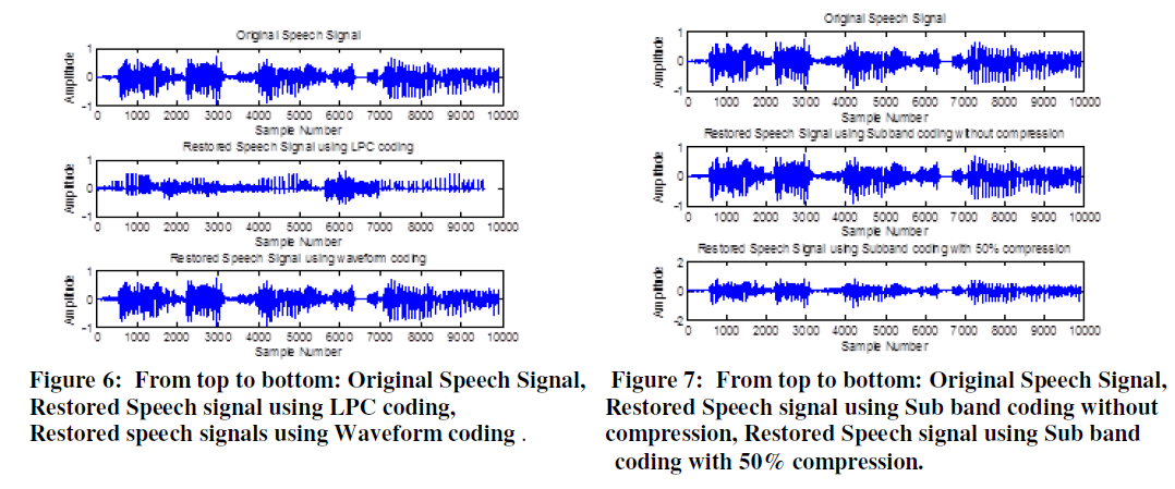 |
VI. CONCLUSION |
| The LPC reconstructed speech has a lower pitch than the original speech. The sub band coding system significantly reduces the error and the compression is controlled by sampling rate conversion and multirate signal processing. The waveform coding will give significant compression and also good quality of sound. |
References |
|