ISSN ONLINE(2320-9801) PRINT (2320-9798)
ISSN ONLINE(2320-9801) PRINT (2320-9798)
| V. Sathiya Priya1 Asst Professor, Indus college of Engineering and Technology, Alandhurai, Coimbatore, Tamilnadu, India |
| Related article at Pubmed, Scholar Google |
Visit for more related articles at International Journal of Innovative Research in Computer and Communication Engineering
The fast paced progress in the Mobile Ad Hoc Networks (MANETs) has enabled the use of a number of wireless applications on the move. These MANETs exhibit heterogeneity in the energy levels. In such a heterogeneous network, different devices are likely to have different capacities and are thus likely to transmit data with different power levels. With high-energy nodes, MANETs can progress network measurability, connectivity, and disseminating validity. However, the throughput of power heterogeneous MANETs can be severely impacted by high-energy nodes. In this paper, we develop a loose-virtual-clumping-based (LVC) expelling rule for power heterogeneous MANETs, i.e., LEPH. To explore the advantages of high-energy nodes, we develop an LVC algorithm to construct a ranked network and to eliminate simplex links. To reduce the disturbance raised by high-energy nodes, we develop expelling algorithms to avoid packet forward via high-energy nodes. We demonstrate the system implementation and experimental results through simulations in Network Simulator [ns2].
Keywords |
| CLVC, Heterogeneous Networks, MANET, Power nodes, Routing, Virtual Clustering |
INTRODUCTION |
| Mobile Ad Hoc Networks, or MANETs, are a type of wireless network with no fixed infrastructure. The clumping of wireless nodes for various network management purposes has been proposed by several researchers for various purposes in network management. |
| Most of the previous work in the literature focuses on clumping nodes for expelling purposes. Srivastava and Ghosh put forth a unique approach to clumped expelling with the creation of two levels of trees with the upper level forming a backbone between the lower layer clumps which also follow a tree structure. These tree structures are formed with procedure based on the goal of minimizing the number of hops between communicating nodes. Sivavakeesar and Pavlou propose a location-based expelling strategy for MANETs, in which a region is broken in a matrix of overlapping, adjacent circles or zones where virtual. Clumps are based on the location of nodes within each zone. This approach looks more strictly at transmission ranges and the nature of links among nodes. In 802.11-based power heterogeneous MANETs, mobile nodes have different transmission power, and power heterogeneity becomes a double-edged sword. On one hand, the benefits of high-energy nodes are the expansion of network coverage area and the reduction in the transmission delay. High- energy nodes also generally have advantages in power, storage, calculation capacity, and data transmission value. As a result, research efforts have been carried out to explore these advantages, such as backbone construction [7] and topology control [8]. On the other hand, the large communication range of high- energy nodes leads to large disturbance, which further dilutes the spatial usage of network channel resources [9], [10]. Because of different transmission power and other factors (e.g., disturbance, barrier, and noise), asymmetric or simplex links will exist in MANETs. Existing research results show that expelling rules over simplex links perform poorly in multihop wireless networks [11]. However, the existing expelling rule in power heterogeneous MANETs are only designed to detect the simplex links and to avoid the transmissions based on asymmetric links without considering the benefits from high-energy nodes. Hence, the problem is how to improve the routing performance of power heterogeneous MANETs by efficiently exploiting the advantages and avoiding the disadvantages of high-energy nodes, which is the focus of this paper. |
| They present a loose-virtual-clumping-based (LVC) expelling rule for power heterogeneous (LEPH) MANETs. To explore the advantages of high-energy nodes, we develop an LVC algorithm to construct a ranked network and to decimate simplex links. To reduce the disturbance raised by high-power nodes, we develop expelling rules to avoid packet forwarding via high-energy nodes. All nodes build a local aware topology (LAT) table by exchanging control packets during building LVC. Notice that the LAT table stores local topology information based on discovered duplex links. They present an effective scheme to discover duplex links. In particular, each node periodically sends a duplex neighbor discovery (DND) packet, containing its own information (e.g., ID, type, state, etc.) and the information on its discovered neighbors. The discovered neighbors refer to the nodes learned by the received DND packet. All nodes build aware neighbor (AN) and BN tables based on the received DND packets. |
| In our clumping, a loose coupling relationship is established between nodes. Based on the LVC, LEPH is adaptive to the density of high-energy nodes. Recall that high-power nodes with a larger transmission range will create large disturbance areas and low channel spatial utilization. In such case, we developed expelling algorithms to avoid packet forwarding via high-energy nodes. We conducted extensive analysis, simulations, and real-world experiments to validate the effectiveness of LEPH. Simulation results show that LEPH achieves much better performance than other existing protocols. We have implemented LEPH in Microsoft WinCE environment and conducted real-world experiments. Our data matches the theoretical and simulation findings well. |
PROPOSED SYSTEM |
| Clustering |
| In clumping procedure, a representative of each sub domain (clump) is ‘elected’ as a clump head (CH) and a node which serves as intermediate for inter-clump communication is called gateway. Remaining members are called ordinary nodes. The boundaries of a clump are defined by the transmission area of its CH. Clump architectures do not necessarily include a CH in every clump. CHs hold routing and topology information, relaxing ordinary MHs (mobile host) from such requirement; however, they represent network bottleneck points. In clump without CHs, every MH has to store and exchange more topology information, yet, that eliminates the bottleneck of CHs. |
| In active clustering, MHs cooperate to elect CHs by periodically exchanging information, regardless of data transmission. On the other hand, passive clustering suspends clumping procedure until data traffic commences [11]. It exploits on-going traffic to propagate “clump-related information” (e.g., the state of a node in a cluster, the IP address of the node) and collects neighbor information through promiscuous packet receptions. Passive clumping eliminates major control overhead of active clumping, still, it implies larger setup latency which might be important for time critical applications; this latency is experienced whenever data traffic exchange commences. On the other hand, in active clumping scheme, the MANET is flooded by control messages, even while data traffic is not exchanged thereby consuming valuable bandwidth and battery power resources. |
PROPOSED WORK |
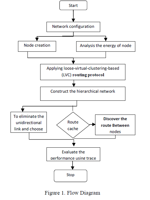
| Here, we introduce the LVC rule. In LVC, simplex links in the network can be discovered using a BN discovery strategy. To exploit the benefits of high-power nodes, LVC establishes a ranked structure for the network. 1) DND: To eliminate simplex links, we present an effective strategy to discover duplex links. In particular, each node periodically sends a duplex neighbor discovery (DND) packet, containing its own information (e.g., ID, type, state, etc.) and the information on its discovered neighbors. The discovered neighbors refer to the nodes learned by the received DND packet. All nodes build aware neighbor (AN) and BN tables based on the received DND packets. Using the BN table, the BNs can be identified. |
| Procedures for discovering BNs: |
| Step 1: Each node broadcasts DND packets within one hop and notifies all neighbors about its type or state. |
| Step 2: After sending DND packets, each node waits for TBND to collect DND packets sent fromits neighbors. The received DND packets will be used to construct the AN table, which stores the information (e.g., ID, type, state, etc.) of all discovered nodes. As a result, |
| AN = NB |
| RB(gi) ∩ NG |
| RG(gi). |
| Step 3: After waiting for TDND, each node broadcasts DND packets again. In this step, the information on the node itself and all nodes in the AN table will be added to the DND packets. |
| Step 4: When receiving DND packets, each node will check whether its own node information is in the DND packets. If so, a duplex link between the current node and the sender of that DND packet will be determined. Then, the sender of the DND packet will be added into the BN table. |
| As a result, BN = NB |
| RG(gi) ∩ NGRG(gi). |
| 2) LVC: To exploit the benefits of B-nodes, we design a novel LVC algorithm. In LVC, a B-node is chosen as the cluster head and establishes a loose coupling relationship with G-nodes. Different from the strong coupling clumping, only Gnodes under the coverage of B-nodes will participate in the clumping. Consequently, only G-nodes in the Gmember or Ggateway state will be involved in the clumping, whereas those nodes uncovered by the B-nodes (e.g., Gisolated) will not be involved in the clumping. Two features appear in LVC. First, the loose clumping avoids heavy overhead caused by reconstructing and maintaining the clump when the density of B-nodes is small. |
| Second, LEPH protocol can be adaptive to the density of B-nodes, even when all G-nodes are in the Gisolated state. All nodes build a local aware topology (LAT) table by exchanging control packets during building LVC. Notice that the LAT table stores local topology information based on discovered duplex links. The detailed procedures for constructing LVC are presented in the following. |
| Procedures for Building LVC: |
| Step 1: Each G-node broadcasts G-node LVC initialization (GLI) packets to all B-nodes in the AN table. The BN information in the BN is added to GLI. Notice that GLI will only be delivered within the limited area controlled by time-tolive (TTL). Because TTL is very small, broadcasting GLI packets will not incur much overhead to the network. |
| Step 2: Each B-node waits for TLVC to collect GLI and build the LAT table for the local topology information local_topo_info based on the BN information in GLI. Then, the B-nodes broadcast B-node LVC initialization (BLI) packets within one hop and notifies local_topo_info to all the G-nodes within its covered range. |
| Step 3: After sending GLI packets in Step 1, the G-nodes wait TLVC for receiving BLI packets from the B-nodes. Then, the G-nodes build LAT based on the local_topo_info received in BLI packets. |
| Step 4: Each G-node determines its own state based on the definitions about G-nodes and selects the clump head using the strategy proposed in Section III-B4. Then, each node takes the following operation according to its state. • If a G-node is in either the Gmember or Ggateway state, it multicasts clump member register (CMR) pa |
| • If a G-node is in either the Gmember or Ggateway state, it multicasts clump member register (CMR) packets to both the new and old clump heads. Notice that CMR packets will only be sent to the new cluster during the initialization. Similar to the GLI packet, the information in CMR contains the BNs. The routes to the new and old clump heads can be obtained based on the topology in LAT table. |
| • If a G-node is in the Gisolated state, it cannot receiveany BLI packets and does not have a cluster head. |
| Hence, the G-node will do nothing. |
| Step 5: Each cluster head waits for TLVC to collect CMR packets from its cluster members and rebuild the LAT for its clump members. The topology information on clump members will be managed by the clump head. Then, the clump head broadcasts clump head declare (CHD) packets to the G-nodes covered by the cluster head in one hop. |
| Step 6: When a G-node receives CHD packets, it knows the topology information and updates the information into LAT. However, the B-node does not process received CHD packets. After the given six steps of initialization, a ranked structure is established. In particular, all B-nodes build the based on the received CMR packets, and all G-nodes build LAT based on the received CHD packets. |
| 3) LVC Maintenance: When links between nodes fail, the maintenance of LVC will be activated. In particular, when node detects any of the following conditions based on the periodical BND packets, it enters the procedure of LVC maintenance. |
| • If node ni does not receive the DND packet from node in the AN table within a time window, should be out of its coverage range. |
| • If node ni receives the DND packet from node and node is not in the AN table, a new link between and should be added. |
| In the following, we present the detailed procedures for G-nodes and B-nodes to maintain LVC, respectively. Procedures for G-nodes to maintain LVC: Step1: G-node ni updates its node state and AN and BN tables. |
| Step 2:•If is the clump head of, the maintaining procedure need to obtain a new clump head. First, calculates the route to the old cluster head in accordance to LAT and then updates the topology information related to in LAT. Second, selects a new cluster head (except in the case when the state of becomes G isolated). Finally, multicasts CMR packets to both the new and old clump heads. Hence, at this moment, node ni registers to the new clump head and notices the old clump that is out of the transmission range of. |
| •If it is a B-node but not the cluster head of leaves the coverage range of B-node, and updates the topology information on in LAT. |
| •If it is G-node and in the BN table, the bidirectional link fails. G member or G gateway nodes send the BN update (BNU) packet to the cluster head for updating the BNs. |
| Step 3: When a B-node receives CMR packets, it broadcast CHD packets. If the clump head receives BNU packets, it broadcasts BNU packets again in one hop. The G-node updates the clump and LAT information in accordance with received packets. |
 |
SIMULATION RESULTS |
| The Network Simulator ns-2.28 is used to analyse the system. The NS2 is a discrete event time driven simulator which is used to analyse the performance of a network. The following parameters give the efficiency of the proposed system. |
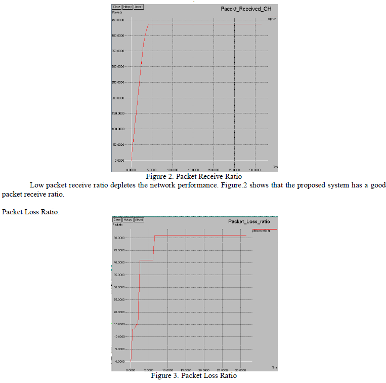
| Packet Receive Ratio: The packet receive ratio is one of the Quality of Service (QoS) metric to evaluate the performance of network. |
 |
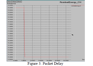
| The Packet Loss ratio is the maximum number of packets possible to be dropped by a node. Figure 3 shows that the packet loss is optimal during the data transmission. Packet Delay: Packet Delay is the delay occurred during data transmission and it is given in figure 4. |
 |
CONCLUSION |
| An MEC based routing protocol named LEPH for power heterogeneous MANETs was developed. LEPH is considered to be a double-edged sword because of its high-power nodes. We designed an MEC algorithm to decimate simplex links and to benefit from high-power nodes in transmission range, processing capability, reliability, and bandwidth. We developed routing schemes to optimize packet forwarding by avoiding data packet forwarding through high- power nodes. Hence, the channel space utilization and network throughput can be largely improved. Through a combination of analytical modeling and an extensive set of simulations, we demonstrated the effectiveness of LEPH over power heterogeneous MANETs using ns2 simulations. |
References |
|