Keywords
|
| Pulse Width Modulation, Space Vector Pulse Width Modulation, MATLAB/SIMULINK, Three Phase Inverter |
I. INTRODUCTION
|
| Three phase voltage source inverters are widely used in variable speed AC motor drive applications since they provide variable voltage and variable frequency output through pulse width modulation control. Continuous improvement in terms of cost and high switching frequency of power semiconductor devices and development of machine control algorithms leads to growing interest in more precise PWM techniques. |
| PULSEWIDTH modulation (PWM) has been studied extensively during the past decades. Many different PWM methods have been developed to achieve the following aims: wide linear modulation range; less switching loss; less total harmonic distortion (THD) in the spectrum of switching waveform; and easy implementation and less computation time. |
| SPACE VECTOR PULSEWIDTH modulation (SVPWM) is one of the most important PWM methods for three phase inverter; it uses the space vector concept to compute the duty cycle of the switches. It is simply the digital implementation of PWM modulators. The relationship between space vectors and fundamental modulation signals was derived in [2] -[3]. |
| In this paper, first a model for Pulse Width Modulation (PWM) based Inverter and Space vector PWM (SVPWM) based Inverter will be made and simulated using MATLAB/SIMULINK software and then the performance of both the techniques will be compared using MATLAB/SIMULINK. |
II. PWM BASED INVERTER
|
| The DC-AC converter, also known as the inverter, converts DC power to AC power at desired output voltage and frequency.[4][5] A complete three phase PWM inverter would consist of three of the single phase inverters with control voltages consisting of sinusoids shifted by 120 degrees between phases. Frequency control in a PWM inverter of this sort is accomplished by changing the frequency of the input control voltage. |
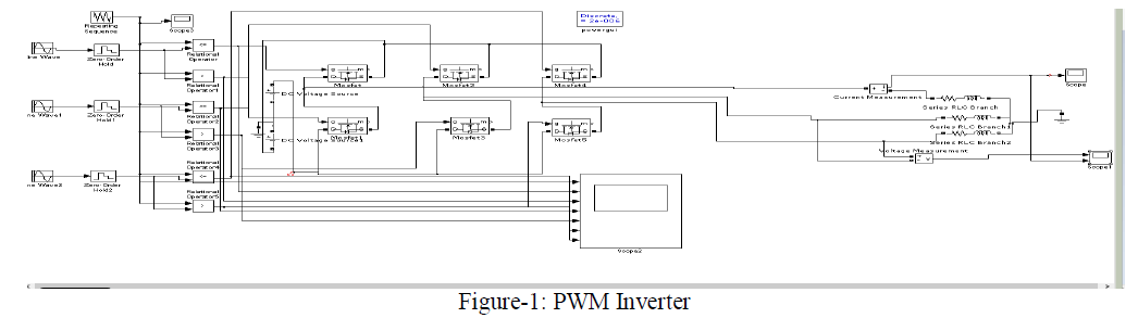
| B. Design of PWM based Inverter scheme |
| The following needs to be defined for the design of the PWM inverter system |
| A model that defines different processes of pulses |
| Implement zero order hold and relational operator to the sine wave. |
| A periodic scalar signal having a waveform that you specify using the Time values and Output values. |
| Following parameters need to be defined to implement a PWM Inverter |
| Sine Wave operates in time-based or sample-based mode |
| Repeating Sequence a periodic scalar signal having a waveform that you specify using the Time values and Output value parameters |
| Zero Order Hold holds the input for the sample period |
 |
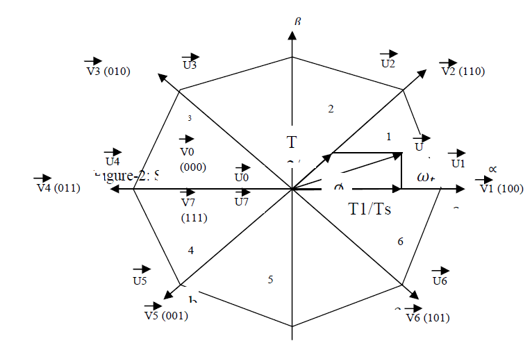
| Space Vector Pulse Width Modulation (SVPWM) was originally developed as a vector approach to Pulse Width Modulation (PWM) for three phase inverter, Space Vector Pulse Width Modulation (SVPWM) method is an advanced; computation intensive PWM method and possibly the best techniques for Induction Motor Drive application.We use this method for less switching losses, hence less total harmonic distortion & this is the advantage of SVPWM |
 |
| Principle of Space Vector PWM |
| The main idea behind SVPWM is to divide the 2D-plane into six equal areas, each of them is called a sector. As shown in Fig.1. Each sector is determined by four vectors via, Vi+1 where I ∈ {1..5} these vectors are called active vectors because when these vectors are applied to the power module the output voltage of the power module, will be greater than zero i.e. one of the switches will not be off. The other two vectors V0 and V7 are called inactive vector, because all switches will be off or on. These two vectors allocate in the center of the circle C of Fig. 1. Vref vector will scan all sectors with the time.For every sample time we can determine the sector containing Vref and calculate the time period for each vector of the determined sector. [6] |
 |
III. SIMULATION RESULTS FOR PWM BASED INVERTER
|
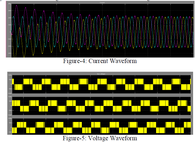
| In the below figure 4 the current waveform has been shown when we draw trhe model using PWM inverter whose MATLAB block diagram shown above. Figure 5 shows the waveform of voltage waveform. |
 |
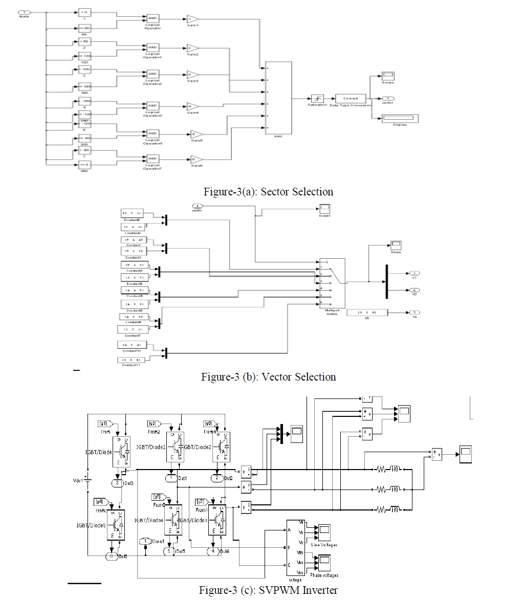
IV. SIMULATION RESULTS FOR SVPWM BASED INVERTER
|
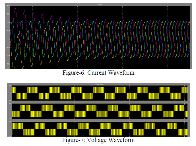
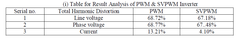
| In the below figure 6 the current waveform has been shown when we draw trhe model using SVPWM inverter whose MATLAB block diagram shown above. Figure 7 shows the waveform of voltage waveform. |
 |
| Result Analysis Of PWM & SVPWM Inverter With Mathematical Model |
| The total harmonic distortion (THD) of Line Voltage of PWM & SVPWM based inverter is 68.72% & 67.18%, respectively, THD of Phase Voltage of PWM and SVPWM based inverter is 68.77% & 67.48% respectively and THD of Current of PWM & SVPWM based inverter is 19.21% & 4.10% respectively. |
 |
V. CONCLUSION
|
| In this paper simulation studies have been carried to show the comparison of operation of PWM and SVPWM based Inverter, Firstly model of PWM inverter is discussed and simulation model of PWM inverter is obtained using MATLAB/SIMULINK is introduced and it is observed that harmonics are present in the simulation result. Hence, for improving the result; we use Space Vector Pulse Width Modulation Technique in our project to improve the harmonics present in current and voltage. Hence Simulation studies indicate that harmonics is reduced in SVPWM based inverter model in comparison to PWM based inverter model and THD of Line Voltage of PWM & SVPWM is 68.72% & 67.18%, respectively, THD of Phase Voltage of PWM and SVPWM is 68.77% & 67.48% respectively and THD of Current of PWM & SVPWM is 19.21% & 4.10% respectively. |
References
|
- Shao-Liang An, Xiang-Dong Sun, Member, IEEE, Qi Zhang, Yan-Ru Zhong, and Bi-Ying Ren, “Study on the Novel Generalized DiscontinuousSVPWM Strategies for Three-Phase Voltage Source Inverters”, IEEE Transactions on Ind. App. May-2013
- Mustafa A. Al-Refai “Matlab/Simulink Simulation Model for Direct Torque Control Based On Space Vector Modulation (DTC-SVM) ofInduction Motor Drive”, International Journal of Electrical and Electronics Engineering (IJEEE), World Academy of Science, Engineering andTechnology ,February-2013
- Y. vijayanandi, U.Sree Krishnakanth2, Rajesh Kumarr3 & K. Laksmi Ganesh4 “New multilevel Cascaded PWM inverter topology for hybridElectrical Vehicle Drive” International Journal of Electrical and Electronics Engineering (IJEEE) , May-2013
- Vaibhav B. Magdum Ravindra M. Malkar ,“Study & Simulation of Direct Torque Control Method For Three Phase Induction Motor Drives”International Journal of Electrical Engineering International Journal of Electrical Engineering and Technology ISSN 0976 – 6553(Online), Volume2,April-2013
- Vaibhav B. Magdum Ravindra M. Malkar, ”Study & Simulation of direct torque Control method for Three Phase Induction Motor drives“,International Journal of Electrical Engineering International Journal of Elect, APRIL-2011
- R K Behera and S P Das, “Improved direct torque control of induction motor with dither injection”, Department of Electrical Engineering, Indian Institute of Technology, Kanpur , OCTOBER-2008
|