Keywords
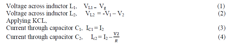
|
| Cuk, PV,Modified Cuk converter, MATLAB. |
I.INTRODUCTION
|
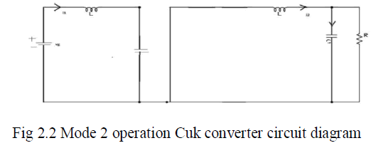
| A photovoltaic system converts light into electrical direct current (DC) by taking advantage of the photoelectric effect. Solar PV has turned into a multi-billion, fast-growing industry, continues to improve its cost-effectiveness, and has the most potential of any renewable technology. Concentrated solar power systems use lenses or mirrors and tracking systems to focus a large area of sunlight into a small beam. Commercial concentrated solar power plants were first developed in the 1980s.In 2011, the International Energy Agency said that "the development of affordable, inexhaustible and clean solar energy technologies will have huge longer-term benefits. It will increase countries' energy security through reliance on an indigenous, inexhaustible and mostly import-independent resource, enhance sustainability, reduce pollution, lower the costs of mitigating climate change, and keep fossil fuel prices lower than otherwise. These advantages are global. Hence the additional costs of the incentives for early deployment should be considered learning investments; they must be wisely spent and need to be widely shared" |
 |
| The DC-DC converter based photo voltaic (PV) energy system is applied in various convenient applications. There are several different types of dc-dc converters, buck, boost, buck-boost and cuk topologies, have been developed and reported in the literature to meet variety of application specific demands. One advantage of these converters has high power efficiency [7] [8] [9].Higher order dc-dc converters, such as the cuk converter, have a significant advantage over other inverting topologies since they enable low voltage ripple on both the input and the output sides of the converter [5]. |
II.CUK CONVERTER
|
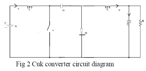
| A non-isolated ̉̉ uk converter comprises two inductors, two capacitors, a switch (usually a transistor), and a diode. It is an inverting converter, so the output voltage is negative with respect to the input voltage.The capacitor C is used to transfer energy and is connected alternately to the input and to the output of the converter via the commutation of the transistor and the diode The two inductors L1 and L2 are used to convert respectively the input voltage source (Vi) and the output voltage source (Co) into current sources. At a short time scale an inductor can be considered as a current source as it maintains a constant current. This conversion is necessary because if the capacitor were connected directly to the voltage source, the current would be limited only by the parasitic resistance, resulting in high energy loss. Charging a capacitor with a current source (the inductor) prevents resistive current limiting and its associated energy loss.As with other converters (buck converter, boost converter, buck-boost converter) the ̉̉ uk converter can either operate in continuous or discontinuous current mode. However, unlike these converters, it can also operate in discontinuous voltage mode (i.e., the voltage across the capacitor drops to zero during the commutation cycle). |
 |
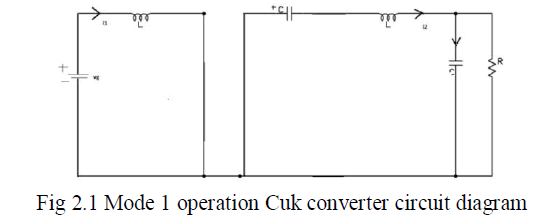
| Mode 1 operation:When switch S is on |
 |
 |
| Mode 2 operation:When switch S is off, |
 |
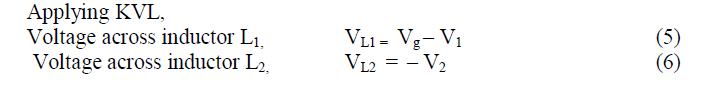 |
 |
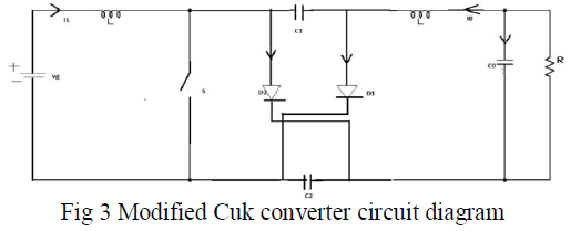
| MODIFIED CUK CONVERTER |
| Hybrid converters can be constructed by inserting either the step-down switching blocks Dn1 ,Dn2 , or step-up switching structures UP2,UP3 , in a classical Cuk converter. Simple switching dual structures, formed by either two capacitors and 2–3 diodes, or two inductors and 2–3 diodes are defined. [2]. |
 |
| Mode1 operation |
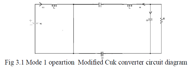 |
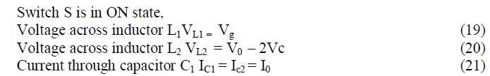 |
| Mode2 operation |
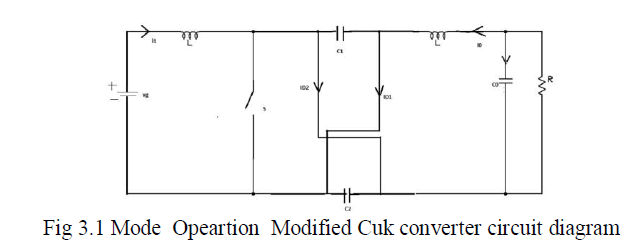 |
| Switch S is in OFF state, |
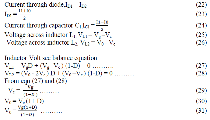 |
III.SIMULATION
|
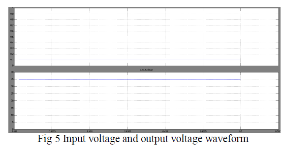
| Cuk converter circuit is simulated using MATLAB SIMULINK Software and various output waveforms like output voltage,inductor currents are obtained by varying the values of duty cycle and load resistance. |
| CUK CONVERTER |
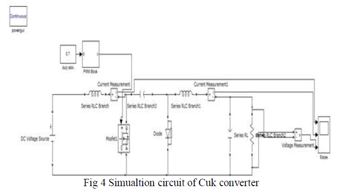 |
 |
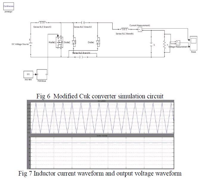
| Modified converter : |
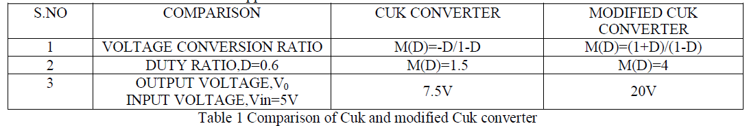
| Modified cuk converter circuit with switched capacitor is simulated using MATLAB Simulink and the output voltage waveform is obtained |
 |
| IV.COMPARISON OF CUK AND MODIFIED CUK CONVERTER |
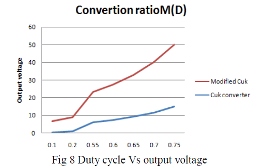
| Cuk converter output voltage equation similar to buck boost converter and the however the output voltage of the modified Cuk converter doesn’t resemble the conventional Cuk conveter,the steed increase in the conversion ratio is shown here and thus suits well for PV applications. |
 |
| The comparison shown with the graph here proves that the Modifed Cuk converter conversion ratio is more in boost mode however when compared to conventional and Cuk converter. |
V.EXPERIMENTAL RESULTS
|
| The experimental results and both the Cuk converter and modified Cuk converter are presented here with the respective output waveforms. Conduction losses and current stress across the switches is reduced and the efficiency of the modified converter is improved. |
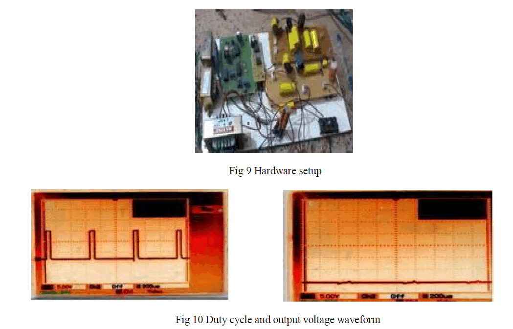 |
VI. RESULT AND DISCUSSION
|
| Hardware for both Cuk converter and modified Cuk converter is analysed by varying duty cycle ,load and input voltage.both line regulation and load regulation is analysed both using simulation and hardware results. |
 |
VII.CONCLUSION
|
| Thus conventional classic Cuk converter cannot offer a steep step-up and step-down of the line voltage. Modified Cuk converter offers steep conversion ratio. This is very much required especially for PV applications The output voltage is very smooth and stable in less time. Output voltage for different values of duty cycle ,load and line regulation is analysed for stability of the system. |
References
|
- Sankarganesh Ramasamy , Thangavel Subbaiya,”An Efficient Modified CUK Converter with Fuzzy based Maximum Power Point TrackingController for PV System”, International Journal of Simulation, Systems, Science and Technology, Vol 13,no 1,pp77-84 Jan 2010.
- Axelrod B., Berkovich Y., Ionovici A.: “Switched-capacitor/ switched-inductor structures for getting transformerless hybrid DC–DC WMconverters”, IEEE Transactions on Circuits and Systems I. vol. 55, no. 2, pp. 687–696. 2008.
- Erickson R., Maksimovic D., Fundamentals of Power Electronics. Second Edition, USA: Kluwer Academic Publishers, 2001.
- Maksimovic D., CUK S.: “Switching converters with wide DC conversion range”, IEEE Transactions on Power Electronics. vol. 6, no 1, pp.151–157, 1991.
- Daho, D. Giaouris, S. Banerjee, B. Zahawi and V. Pickert, "Fast-Slow Scale Bifurcation in Higher Order Open Loop Current-ModeControlled DC-DC Converters", International Federation of Automatic Control, Vol.2, No.1, 2009.
- K.Kavitha, Dr. Ebenezer Jeyakumar"A Synchronous Cuk Converter Based Photovoltaic Energy System Design and imulation"InternationalJournal of Scientific and Research Publications, Volume 2, Issue 10, October 2012.
- M.SubbaRao, Ch.Sai Babu and S.Satynarayana, "Analysis and Control of Double-Input Integrated Buck-Buck-Boost Converter For HybridElectric Vehicles", International Journal of Advances in Engineering & Technology, Vol.1, No.4, pp.40-46, 2011.
- C.K.Tse, Y.S.Lee and W.C.So, "An Approach to Modelling DC-DC Converter Circuits Using Graph Theoretic Concepts", InternationalJournal of Circuit Theory and Application, Vol.21, pp.371-384, 1993.
- Y. Fuad, W. L. de Koning and J. W. van der Woude, "Pulse-width modulated d.c.–d.c. converters", International Journal of ElectricalEngineering Education, Vol.38, No.1, pp.54-79, 2001.
- C. K. Tse, " Circuit theory of power factor correction in switching converters" International journal of circuit theory and applications,Vol 31,pp 157-98,2003.
|