Keywords
|
| DC-DC converter, Matlab, positive output Relift LUO converter, Proportional Integral control simulink |
INTRODUCTION
|
| The positive output Relift LUO converter gives the voltage gain interms of arithmetic progression instead of geometric progression of conventional Dc to Dc converters. The main objective is to reach high efficiency, high power density and cheap topology in a simple structure. Due to the effect of parasitic elements, the output voltage and power. Transfer efficiency is restricted in DC –DC converter. The voltage-lift technique is a popular method that is widely applied in electronic circuit design. It can open a good way of improving DC-DC converters characteristics and has been successfully applied for DC-DC converters. Traditional frequency-domain analog methods predominantly used in controller design are based essentially on an equivalent linear small-signal model of the converter concerned. Under line and load disturbances the output voltage of the converter is regulated with the help of development PI controller. stability, large line and load variation robustness, good dynamic response are the essential features of PI control technique fast dynamic response for line side and load side disturbances with output voltage regulation is used to ensure the choice of specific PI controller. Zero steady state error and fast response is brought forward with PI control. a good alternative to the control of switching power converters is implemented wi th PI control a PI control is a more feasible approach to ensure the correct operation in any working condition to optimize the stability of positive output Relift LUO converter. PI control for negative output Re lift LUO converter is studied in Matlab/Simulink is evaluated for the performance of both static and dynamic performance. |
RELATED WORK
|
| In [1]used voltage lift technique for DC-DC converters, Converters which eliminates the auxiliary switch in the original Positive Output Luo-Converters yet perform the same functions. They are different from any other existing DC-DC step-up converters and possess many advantages including the high output voltage with smooth ripples. In [2]Proposes a PI controller positive output elementary LUO converter The object of this paper is to design and analyze a proportional – integral (PI) control for positive output elementary super lift Luo converter (POESLLC), which is the start-of-the-art DC-DC converter. Using state space average method derives the dynamic equations describing the positive output elementary super lift luo converter and PI control is designed.In [4] IntrtroducesThe voltage-lift technique using voltage-lift circuit has been successfully applied to several series of DC-DC Luo converters. However, the voltage-lift circuit definitely has an unavoidable influence on the overall converter performance. It is attempted to clarify such an effect. Four converters with voltage-lift circuit are analysed: positive output self-lift Luo converter, positive output super-lift converter, negative output self-lift Luo converter and positive output re-lift Luo converter.In[5]Proposes the new advanced converter if re lift LUO converter. A re-lift circuit, which is a new DC-DC step-up (boost) converter ,is proposed. This converter performs positive to positive DC-DC voltage increasing conversion With high output voltage The voltage lift technique is a technique applied in lifting the output voltage without using any external circuit, just by using the passive components.In [6] propose positive output LUO converters in Hand book of Power electronics. The Positive output (N/O) Luo-converters performs voltage conversion from positive source to positive load voltages using the voltage-lift technique. They work in the First quadrant with large voltage amplification, and their voltage-transfer gain is high. Double output Luo-converters perform the voltage conversion from positive to positive and negative voltages simultaneously using the voltage-lift technique. They work in the first and third quadrants with large voltage amplification, and their voltage-transfer gain is high. Based on the Positive Output Luo-Converters and Negative Output Luo-Converters. |
LUO CONVERTERS
|
| The elementary LUO converter performs buck or boost operation in Dc to Dc conversion. The positive output LUO converter performs the conversion from positive input source voltage to positive output load voltage. Self-lift, Re lift, triple-lift, quadruple-lift and super-lift converters are the types of LUO converters which are derived from their appropriate elementary circuits with the help of voltage lift techniques. Reduction of value of duty ratio as well as effect of parasitic elements can be easily acquired by the voltage lift technique.luo converters have the characteristics of high voltage transfer gain, high power density, and reduced ripple in voltage and current in simple topology. |
| A. Positive Output LUO Re-lift Converter |
| The positive output Relift converter circuit is shown in fig 1.it consists of two MOSFET switches namely S,S1.three inductors Lo,L1,L2 four capacitors C,C1,C2,C3 and the diodes D1,D2,D3. The positive output re-lift LUO (PORLL) converter has two voltage lift circuits and the converter is shown in Fig. 1. Compared with the PORLL converter, an extra VLC, which consists of a capacitor C2 and a diode D2, is added to the circuit. Another switch S1 is implemented, as shown in the Figure. It is turned on and off at the same time as the switch S. Two capacitors, C1 and C2,are the same .The equivalents circuits of the PORLL converter during switch-on and switch-off periods are shown in and, respectively. It shows the equivalent circuit when the converter operates in DCM. |
| During switch-on period, the voltages across the two inductors L1 and L2 are the same, which is equal to the input voltage Vin. Capacitors C1 and C2 are charged rapidly to the source voltage Vin. The average voltage of the pump capacitor C, Vc, is also equal to the output voltage Vo and it is discharged with current iLO. The average value of the voltage across the inductor LO is also equal to source voltage during this period because VC is equal to Vc. |
| According to Fig. 3, switch-off period current iL1 and iLO flow through inductor L2 during. As the inductor current iL2 cannot be changed discontinuously, the current difference between iL2 (kT) and iL1 (kT) +iLO (kT) should flow through the diode D2 until the difference is zero. Avoid this problem, it should be maintained that iL2(kT) = iL1(kT) + iLo (kT) |
| The switch is ON for period kT and OFF for (1-kT) period. The output voltage and current are |
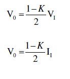 (1) (1) |
| The voltage transfer gain in continuous mode is |
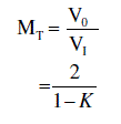 (2) (2) |
| Average current |
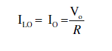 (3) (3) |
| The Current through Inductor L1 is |
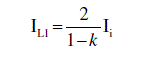 (4) (4) |
| The Current through Inductor L2 is |
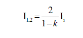 (5) (5) |
DESIGN OF PI CONTROLLER
|
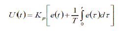
| The nominal operating point for positive output Relift LUO converter can be achieved desired specific PI control, so that sudden load, disturbances and set point variations stays are very closer to the nominal operating point. With the help of Zeigler – Nichols tuning method proportional gain (Kp) and integral time (Ti) are designed by applying the step test obtain S – shaped curve of step response of PORLLC. Which may be may be characterized by two constants, delay time and time constant. The delay time is computed by drawing a tangent line at the inflection point of the S-shaped curve. Intersections of the tangent line with line output response and Time axis the value of time constant is calculated. With the help of Zeigler – Nichols tuning method proportional gain (Kp) and integral time (Ti) are designed from the above calculated value. |
 |
SIMULATION OF RE LIFT LUO CONVERTER
|
| The simulation has been performed on the positive output Relift lift LUO converter circuit with parameters listed in Table I, Simulation Circuit was shown in Fig 4. The static and dynamic performance of PI control for the positive output re lift LUO converter is evaluated in Matlab/Simulink |
| The difference between feedback output voltage and reference voltage is given to PI control and output of PI control, change in duty cycle of the power switch ( n - channel MOSFET). |
| The positive output Re lift LUO converter performance is done for transient region, line variations and load variations |
| A. Transient Region |
| The Figure 5 Shows the Output Voltage of Positive Output Relift LUO Converter with PI Control in Transient Region, Which Shown that the Output Voltage Settled at 0.016sec for the specified PI Control. |
| B.Supply Disturbances |
With supply variation of +5V
|
| Fig.6 shows the output voltage of converter for input voltage step change from 12 V to 17 V (+5v supply disturbance).the converter output voltage has maximum overshoot of 4V and 0.003sec settling time with designed PI control. Fig.7 shows the output voltage variations for the input voltage step change from 12 V to 9 V (-5V supply disturbance).the converter output voltage has maximum overshoot of 2 V and 0.003 sec settling time with designed PI control |
With supply variation of -5V
|
| C.Load Disturbance |
With load change of 20%
|
| Fig.8 shows the output voltage with change the load from 250 ? to 200 ? (-20% load disturbance).the maximum overshoot is 0.6 V and settled at the 0.005 sec .Fig.9 shows the variation of load from 250 ? to 275 ?(+20% disturbance) the maximum overshoot of 0.003 V and settled at 0.00 sec. |
| With load change of 20% |
CONCLUSION
|
| The Positive Output Relift lift LUO converter (PORLLC) performs the voltage conversion from positive source voltage to Positive load voltage.In this paper PI control scheme has proved to be robust and it has been validated with transient region, line and load variations for PORLLC. The Positive output re lift LUO converter with PI control use in applications such as switch mode power supply, computer peripherals and high voltage projects etc. |
| |
Tables at a glance
|
 |
|
| Table 1 |
Table 2 |
|
| |
Figures at a glance
|
 |
 |
 |
 |
 |
| Figure 1 |
Figure 2 |
Figure 3 |
Figure 4 |
Figure 5 |
 |
 |
 |
 |
| Figure 6 |
Figure 7 |
Figure 8 |
Figure 9 |
|
| |
References
|
- Luo.F.L and Ye.H, “Positive output super lift converters,” IEEE Transaction on power electronics, Vol.18, No. 1, pp. 105-113, January 2003.
- Ramesh kumar.K and Jeevanantham.S.“ PI Control for positive output elementary super lift luo converter,’’ World Academy of Science, Engineering and Technology. pp. 732-737, March 2010.
- Kayalvizhi.R ,Natarajan.S.P and Padmaloshani.P” Development of a Neuro Controller for a Negative output Elementary Luo Converter”Journal of Power Electronics, Vol. 7, No. 2, April 2007
- Luo, F.L. 1998. “Luo-Converters, Voltage Lift Technique”. Proceedings of the IEEE Power Electronics Specialist Conference IEEE PESC’ 98. Fukuoka, Japan, May 17- 22 1997. 1783-1789.
- Luo F.L. 1998. “Re-Lift Converter: Design, Test, Simulation and Stability Analysis”. IEE – EPA Proceedings. July 1988. 145(4):315- 325.
- Luo, F.L. 1997. “Re-Lift Circuit: A New DC-DC Step- up (Boost) Converter”. IEE - Electronics Letters. 2nd January 1997.
- Rashid.M.H Power Electronics Hand Book, ..Ed., Academic, San Diego, CA, Aug.2001.
- Luo, F.L. 1997. “Luo-Converters: A Series of New DC-DC Step-up (Boost) Conversion Circuits”. Proceedings of IEEE International Conference PEDS’97. 26-29 May 1997. Singapore. 582-588.
- JosephBasanth,A ,Natarajan.S.P and Sivakumaran.T.S, Simulation and DSP based implementation of double output elementary luo converter, International Conference PESA-09, Hong Kong.
|