Keywords
|
| Power quality, controller design, PI controller, STATCOM. |
I. INTRODUCTION
|
| Electrical utility and heavy industry face a number of challenges related to reactive power. Heavy industrial applications can cause phenomena like unbalance, distortion or flicker on the electrical grid. Electrical utilities may be confronted with phenomena of voltage sags, poor power factor or even voltage instability. Reactive power control can solve these issues. The most advanced solution to compensate reactive power is the use of a Voltage Source Converter (VSC) incorporated as a variable source of reactive power. These systems offer several advantages compared to standard reactive power compensation solutions. Reactive power control generated by generators or capacitor banks alone normally is too slow for sudden load changes and demanding applications, such as wind farms or arc furnaces. Compared to other solutions a voltage source converter is able to provide continuous control, very dynamic behavior due to fast response times and with single phase control also compensation of unbalanced loads. The ultimate aim is to stabilize the grid voltage and minimize any transient disturbances. |
| STATic synchronous COMpensator (STATCOM) is essentially an ac-voltage source where the magnitude, the phase angle and the frequency of the output voltage can be controlled [1]. The building block of the STATCOM is a voltage source converter (VSC) consisting of connected semiconductor valves and a capacitor on the dc side. The device is shunt connected to the network through a coupling inductance that is usually represented by the transformer leakage reactance. The described basic circuit is presented in Fig. 1. In general, the STATCOM can provide power factor correction, harmonics compensation and load balancing. The major advantages of STATCOM in comparison with a conventional static var compensator (SVC) include the ability to generate the rated current at virtually any network voltage, a better dynamic response and the use of a relatively small capacitor on the dc side. The size of the capacitor does not play an important role in steady-state reactive power generation, which results in a significant reduction of the overall compensator size and cost. The STATCOM operation under unbalanced conditions occurs when the compensator exchanges negative-sequence current components with the network. The sources of unbalanced conditions can be roughly divided into two cases. The first case concerns voltage unbalances where mild unbalances are caused by unbalanced loads, while severe unbalances are the consequence of power system faults. As a consequence large negative-sequence currents may flow between the compensator and the network. Unbalance in network voltage also causes voltage distortion on the dc side of the converter and consecutively the generation of low order harmonics on the ac side [2, 3]. The second case concerns a compensator that is used for compensation of unbalanced loads. The dc-side voltage distortion and low order harmonics generation are a major problem also in this case. The over-current problem was addressed in some papers [4, 5] and load balancing described in [6–8]. However, the problem of dc-side voltage distortion is not thoroughly analyzed and is usually solved with the use of a sufficiently large capacitor allowing the reduction of the voltage ripple and increasing the size and cost of the device. Moreover, the STATCOM operation under unbalanced conditions is not analytically formulated thus making the development of an effective control algorithm difficult. The power factor PF is defined as the ratio of the active power P to the apparent power S . Thus |
| PF = P/S (1) |
| For purely sinusoidal voltage and current, the standard expression is obtained as |
| PF = cosΦ |
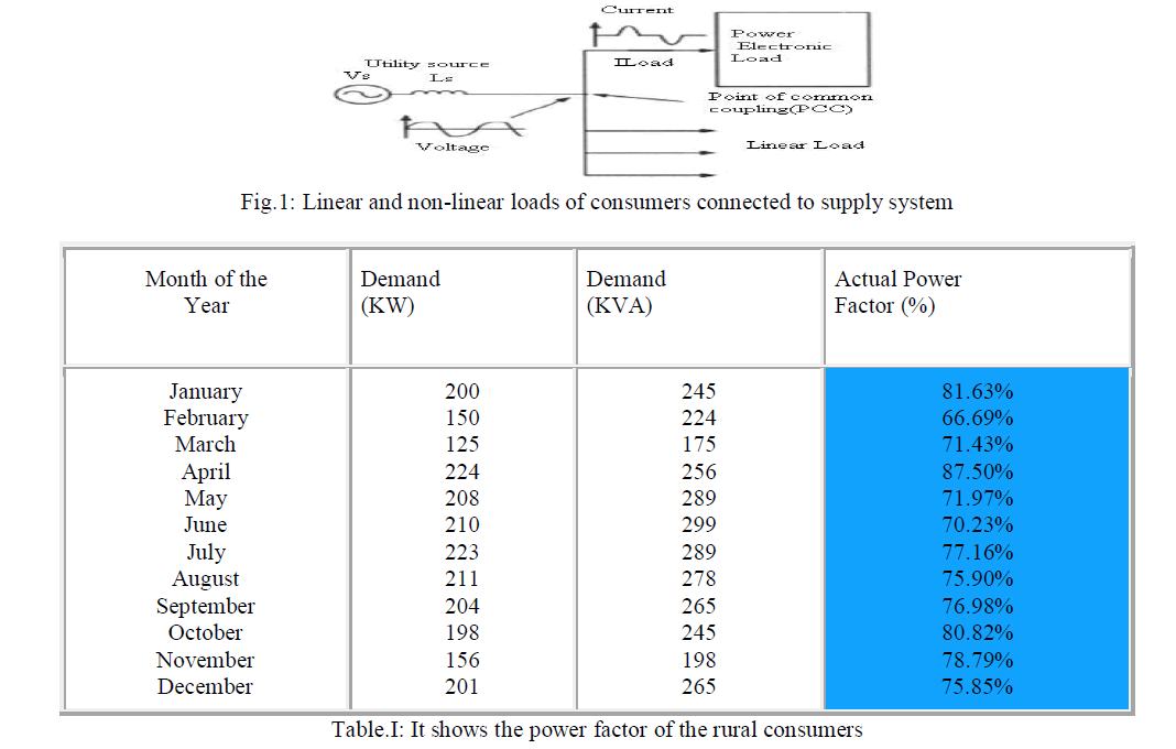
| where cosΦ is popularly known as the displacement factor. The survey of the power factor for a year of the rural consumers is given in Table.I |
 |
| The controllable reactive power allows for a rapid control of bus voltage and power factor at the system or at the load end. To compensate for the distorted current drawn by the rectifiers from the utility grid, the STATCOM and its current controller must have the capability to track source PWM (Pulse Width Modulation) converters. The linear control is more suitable for STATCOM application reported in [9-11]. The present paper suggests the design of a linear current controller and voltage controller on the basis of gain and time constant adjustment along with the parameter of the coupling inductor and storage capacitor. |
| The present paper goes on to develop closed loop model for investigating transient performance of the STATCOM by using controller parameter. First, in Section 2 focuses on modeling of the power system and Section 3 gives state space model of the STATCOM with the system. Secondly, in Section 4, a current and voltage controllers are designed. The simulated responses with the designed controller parameters are presented in Section 5. This scheme is both an extension and a significant improvement of the scheme suggested by Shauder et al [9] .The results obtained have been compared and appropriate conclusions have been drawn. |
II. MODELING OF THE POWER SYSTEM
|
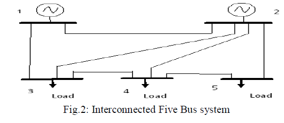 |
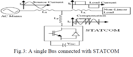
| The 5-bus system is a simple power system network given in Fig.2. The 5-bus system is intended to illustrate in a simple context notions of transfer capability and the impact that various actions have on the given transfer capability. Buses 1, 2 of the system diagram are generators and buses3, 4, 5 of the diagram are loads. The primary flow of power is from the top of the diagram to the bottom of the diagram. Reactive demand by the loads (signified by the empty portion of the load arrows) is large. The network has 7 branches and each branch represents a transmission line. The model is an AC power flow model; it represents real and reactive power flows and power system nonlinearity. Operational limits relating to transmission line flow, voltage magnitude, and voltage collapse are represented. The weak bus no 5 is connected to industrial area and also local consumers. The power factor of this grid (Bus no.5) is poor and hence its power factor can be improved as the model given in Fig.3. |
 |
III. MODELING OF THE STATCOM AND ANALYSIS
|
| A. Operating principle: |
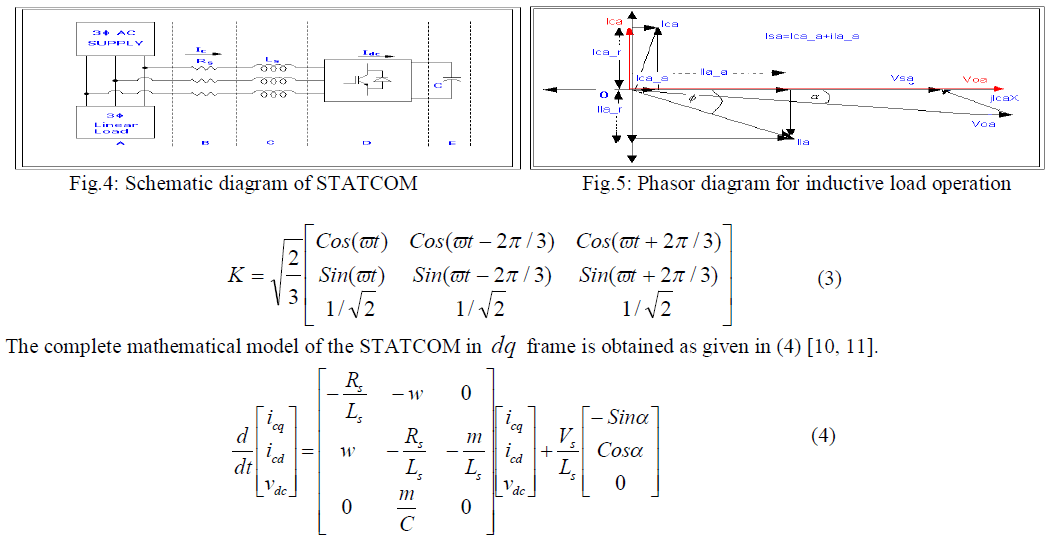
| As is well known, the STATCOM is, in principle, a static (power electronic) replacement of the age-old synchronous condenser. Fig.4 shows the schematic diagram of the STATCOM at PCC through coupling inductors. The fundamental phasor diagram of the STATCOM terminal voltage with the voltage at PCC for an inductive load in operation, neglecting the harmonic content in the STATCOM terminal voltage, is shown in Fig.5. Ideally, increasing the amplitude of the STATCOM terminal voltage oa V above the amplitude of the utility voltage sa V causes leading (capacitive) current ca I to be injected into the system at PCC as shown in Fig.4. |
| B. Modeling: |
| The modeling of the STATCOM, though well known, is reviewed in the lines below, for the sake of convenience. The modeling is carried out with the following assumptions: |
| 1) All switches are ideal |
| 2) The source voltages are balanced |
| 3) Rs represents the converter losses and the losses of the coupling inductor |
| 4) The harmonic contents caused by switching action are negligible |
| The 3-phase stationary abc coordinate vectors with 1200 apart from each other are converted into αβ 2-phase stationary coordinates (which are in quadrature). The α axis is aligned with a axis and leading β axis and both converted into dq two-phase rotating coordinates. The Park’s abc to dq transformation matrix is given in (3). |
 |
| C. Steady State and transient Analysis: |
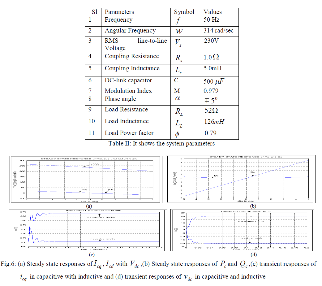
| The detailed steady state and transient responses with the Table.II are given in Fig.6 and responses suggest the static and dynamic conditions of the STATCOM. It can be seen that the transient responses take about one and half power cycle to reach at their steady state values. |
 |
IV. DESIGN OF CONTROLLERS
|
| With the assumption of the system voltage and STATCOM output voltage are in phase and hence the equation (4) can be modified as given in equation (5) |
 |
| A. Design of current controller: |
| The current controller design for the above system can be done using the strategy [12-14] attempts to decouple the d and q axes equations (given in (5)), so that the MIMO system reduces to two independent Single Input Single Output (SISO) system. Hence, the control inputs vod and voq are configured as |
 |
| The equation (7) can be obtained by replacing (5) by (6) and from the circuit parameters Ls and Rs given in Table.II, value of PI parameters are given in equation (8). |
 |
| B. Design of voltage controller: |
| The relation between dc voltage dc v and dc current dc i is |
 |
| C. Proposed control strategy for power factor improvement: |
| The proposed block diagram for this closed-loop system is shown in Fig.7. It has an inner current control loop and an outer voltage control loop. The inner (current) controller acts much faster than the outer (voltage) controller due to obvious reasons. The reactive component of the STATCOM current, cq i , is compared with the reference reactive current, * cq i , (reactive component of the load current, lq i ). The error is passed through a PI-controller (designed in (8)), which yields the controlled voltage. The reactive component of the STATCOM converter terminal voltage is generated as shown in control scheme (Fig.7). The active component of the STATCOM current, cd i , decides the active power flow into the converter (making up for the system losses). The DC-link voltage controller (11) generates the reference current, * cd i , to the PIcontroller of cd i . The d -axis component of the STATCOM converter terminal voltage is produced by summation (proper sign) of the controlled voltage from PI-controller of cd i , q -axis component of the voltage drop of the series inductor and active component of the grid voltage. The unit vectors sin wt and coswt are generated and the reference vector is aligned along the d -axis, which is achieved by maintaining zero phase-difference between the phase voltage, v (t) sa and the unit vector, sin wt . Hence, the d and q -axes of the STATCOM converter terminal reference (rotating) voltages, * o,dq v , with unit vectors, are transferred back to α-β stationary variables. The six logic pulses for the switching devices of the STATCOM are generated in α-β stationary frame with help of Space Vector Pulse Width Modulation (SVPWM) |
 |
| D. System model: |
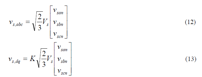
| The three-phase PCC voltages as given in equation (12) assuming no zero sequence components and are transformed to d-q variables as shown in equation (13). Thevenin equivalent voltage source as seen from the PCC terminal into the network is given in Fig.8. |
 |
 |
| The PCC voltage magnitude is defined as: |
 |
| Now substituting equation (16) in equation (15) yields |
 |
| E. Design of PCC voltage controller: |
| Assuming the balanced system, the PCC voltage with current controller can be shown in Fig.9. The arbitrary bandwidth can be assigned to the closed loop system by using a PI-controller as given in equation (18). |
 |
| The open loop transfer function with Fig.9 is given in equation (19) and with Bode plot and assuming first order transfer function; the parameters of PI have been designed and given in equation (20). |
 |
| F. Proposed control strategy for voltage regulation: |
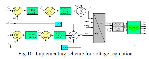
| The proposed block diagram for this closed-loop system is shown in Fig.10. This control block is same as given in Fig.7 with extra PCC control loop and the controlled reactive current from PCC controller is the reference of the reactive current controller. |
 |
V. SIMULATION RESULT
|
| A. Simulation Result of the load: |
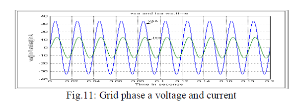
| A linear load, simulated with R ïÃâ¬Ã L parameters (given in Table.II), is connected to the grid. The waveforms of the grid side phase-a voltage ( sa v ) and current ( sa i ) at point of common connection (PCC) (without the STATCOM in operation) are shown in Fig.11. It may be mentioned that here and elsewhere (unless otherwise mentioned) sa v is plotted to a reduced scale of 10:1. Under steady state it is seen that the power angle is 39.640 (so that power factor is 0.77 ). The STATCOM will now act in closed-loop with this system along with the proposed controllers in order to improve this power factor. |
 |
| B. Simulation results with STATCOM for power factor improvement: |
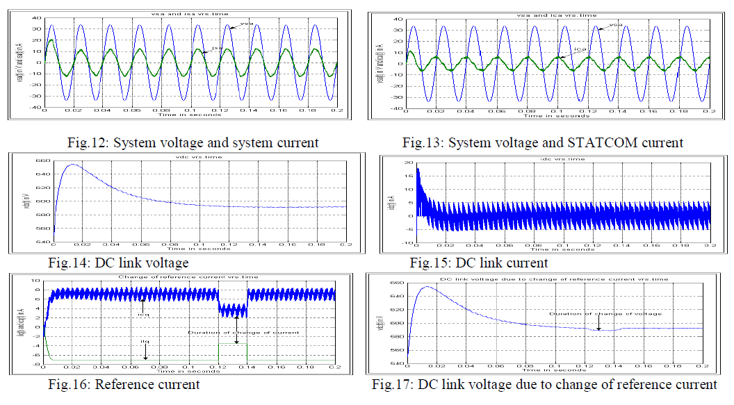
| Then after PI controller is applied to control DC link voltage and PI controllers are used to control d and q axis current of STATCOM using the control block as given in Fig.7. These controllers work and STATCOM functions at initial value of DC link voltage less than 550V. The relevant outputs at initial DC link voltage of 550V are shown in Fig.12 to Fig. 18 . Fig12 shows the dynamics of system voltage and system current after using PI controller at DC link voltage and it shows the over shoot of only 20A and improves power factor after one cycle with respect to Fig. 11 and also the same dynamics is obtained in case of STATCOM current as shown in Fig.13. Figs.14 and 15 show the dynamics of DC link voltage and current obtaining transient up to four cycles. Figs.16 and 17 show very small change of STATCOM current and DC link voltage due to change of reference current(reactive current of load) which shows the robustness of the controller. The system voltage and the STATCOM voltage are shown in Fig.18 and both are in-phase as it signifies for linear model. These controllers work well without spike at initial voltage of 700V as shown in Fig.19 of system voltage .The improvement of power factor and hence improvement of power quality of the system by these controller as given in Fig. 19 with compare to Fig. 11 . |
 |
 |
| C. Simulation results with STATCOM for voltage regulation: |
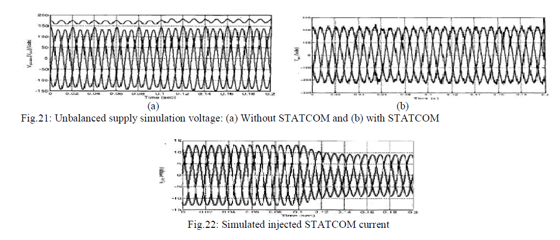
| Fig.20 (a) shows that without compensation, the voltage increases by approximately 6% from 167 V to 174 V when the load reduces. Fig.20 (b) shows the compensated simulated waveform with respect to Fig. 20(a). Due to unbalanced supply, simulated waveform without and with the STATCOM are given in Figs.21 (a) and (b) respectively. The improvement of power quality (no swell and sag) is given in Fig. 21(b) with compared to Fig. 21(a). Fig. 22 shows the system response and injected current when the STATCOM is connected to the supply system. |
 |
 |
VI. CONCLUSION
|
| The STATCOM compensator is a FACTS device which can operate in current control mode for compensating voltage variation, unbalance and reactive power and in voltage control mode as a voltage stabilizer. The investigations of performance of the STATCOM for the power factor improvement and voltage regulation at distribution supply system have |
References
|
- N.G. Hingorani, L. Gyugyi, Understanding FACTS: Concepts and Technology of Flexible AC Transmission Systems, IEEE Press, New York, 2000.
- A.M. Gole, M. Mohades, S. Elez, Steady state frequency response of STATCOM, IEEE Trans. Power Deliv. 16 (1) (2001) 18–23.
- A. Ekstrom, Y. Jiang, General analysis of harmonic transfer through converters, IEEE Trans. Power Electron. 12 (2) (1997) 287–293.
- R. Lasseter, C. Hochgraf, Statcom controls for operation with unbalancedvoltages, IEEE Trans. Power Deliv. 13 (2) (1998) 538–544.
- Y. Jiang, A. Ekstrom, Applying PWM to control overcurrents at unbalanced faults of forced-commutated VSCs used as static var compensators, IEEETrans. Power Deliv. 12 (1) (1997) 273–278.
- A. Ghosh, A. Joshi, The use of instantaneous symmetrical components for balancing a delta connected load and power factor correction, ElectricPower Syst. Res. 54 (2000) 67–74.
- B.N. Singh, et al., Digital implementation of an advanced static compensator for voltage profile improvement, Electric Power Syst. Res. 54 (2000)101–111.
- B. BlaÃâ¦Ã¾iÃâ¹Ãâ¡c, I. PapiÃâ¹Ãâ¡c, P. Ãâ¦Ã½unko, Modeling and simulation of a shunt active filter, UPEC 2002 Proc. 1 (2002) 47–51.
- C.Shauder and H.Mehta, “Vector analysis and control of advanced static VAR compensators”, IEE Proc, 140, No. 4, July 1993.
- A. Draou, M. Benghanem and A. Tahiri, “Multilevel Converter and VAR Compensation”, Power Electronics Handbook”, pp.599-611, AcademicPress, 2001.
- M.Sengupta,J.KMoharana and A.Sengupta,“ Study on an Advanced Static VAR Compensator switched from a Space Vector PWM inverter –Analysis, simulation and comparison with the conventional sinusoidal PWM, NPEC 2003, IIT Bombay,16-17 Oct 03 pp 72-78.
- D.M.Brodand D.W. Novotny, “Current control of VSI- PWM inverter ”IEEE Trans. Industrial Appl,Vol.IA-21, pp.562- 70, July/Aug.1985.
- S.Buso, L.Malesani and P.Mattavelli, “Comparison of Current ControlTechniques for Active Filter Application ”IEEE Trans. Industrial Electronics,Vol.45, No.5, pp.722-729, October 1998.
- P. S. Sensarma, K. R. Pa.diayar and V. Ramanarayanan, "Analysis and Performance Evaluation of a Distribution STATCOM for CompensatingVoltage Fluctuations," IEEE Transactions on Power Delivery, vol 16. no. 2, April 200 I
|