Keywords
|
| Coupled lines, directional couplers, microstrip. |
I. INTRODUCTION
|
| Microstrip directional couplers have been commonly used in microwave systems for measuring transmitted and reflected power with accuracy. They have several advantages. Such as manufacturability, |
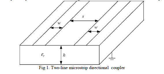 |
| repeatability, and low cost. Extensive research has been conducted on the design of microstrip directional couplers due to their widespread application. The existing design procedures in the literature depend on knowledge of the physical geometry of the directional coupler. As a result, available design charts give physical dimensions of the direction al coupler versus even-and odd-mode impedances of the directional coupler. However, in practice, the physical length of the directional coupler is initially unknown to the designer. Designers have only information about the port impedances, the required coupling level, and the operational frequency at the initial stage of their design. Because of this, it is quite cumbersome to use existing design chats with no prior knowledgeof the geometry of the directional coupler. This requires several iterations to finalize the design.The geometry of a symmetrical micro strip directional coupler is shown in fig. 1. |
| The methods given by Bryant and Weiss [1] and Kirschning and Jansen [2] are among the first reliable and accurate methods to obtain information on coupled microstrip transmission lines. Many researchers used techniques similar to the ones presented in [1] and [2] and studied micro strip directional coupler design for more than 30 years. However, design charts in the literature give only the physical parameters of the directional coupler versus the even-and oddmode impedances and, as a result, are not practically applicable on real applications. One has to use these charts and work backward to obtain the required design parameters for be directional couplers. This is a quite tedious and inefficient way of deigning any RF/microwave device. Akhtarzad etal . [3] give a design method that seems to reflect the design procedure that finds an application in practice. In [3], the synthesis technique is used, and it has an intermediate step of calculating the strip width of the single micro strip line that corresponds to even-and odd-mode impedances of the coupled lines. However, some critical corrections have to be applied to the formulations given in [3] to have accurate results. There are two separate corrections reported by Hinton [4] and Gupta etal . [5] for the work in [3]. Although the error seems to be reduced in comparison to the one in the original work [3] with the application of each correction, the error can still be more than 10% for the low-permittivity materials such as Teflon and for small values of shape and spacing ratios if the correction in [4] and [5] are not employed together. We report that when the corrections in [4] and [5] are employed together, the accuracy of the results increases and the error reduces to within 3% with the experimental results, even when using low-permittivity materials such as Teflon and FR4. This is reported by Eroglu [6]. However, in [6], the method has only been applied on Teflon and FR4, and design charts and parameters have not been given or discussed. Design charts are critical in the design process and make it possible to design directional couplers without using any equations. In addition, the method accuracy has not been verified using different dielectric materials before. Furthermore, the application of the corrections on the formulations has not been presented. |
| In this paper, a three-step deign procedure with accurate closed formulas that give a complete design of symmetrical two-line microstrip directional couplers that include the physical length at the desired operational frequency is introduced. Our design procedure requires knowledge of the port termination impedances, the coupling level, and the operational frequency. We also give the design charts that are most needed by the designer. Our design charts obtained for the five most popular materials used in microwave applications: alumina, Teflon, RO4003, FR4, RF-60. In the design charts, the coupling level is given versus the physical dimensions of the directional coupler. We also provide design charts that show the physical length of the directional coupler l versus the frequency for the given coupling level. We validated our analytical results with the planar electromagnetic (EM) simulation tool [7] and then experimentally verified them. We show that the error between the analytical and the simulation results is reduced to be within 0.2% for high-permittivity materials like alumina. The complete design of a two-line microstrip directional coupler can be obtained for the first time using our results in this paper. A designer can use either the closed-form solutions or the design charts presented here to have a complete design. |
II. FORMULATION AND SOLUTIONS
|
| In real world engineering applications, the physical parameters of the directional couplers are unknown to the designer at the beginning of the design. The only information available to the designer at the beginning of design is the port termination impedances, the coupling level, and the operational frequency. In practice, the termination impedance for each port of the directional coupler is desired to be 50Ω for most applications. The matched system is accomplished when the characteristic impedance zo |
 |
| is equal to the port impedance. The existing design procedure begins with finding the even-and odd-mode impedances oe z and oo z by using the charts given for w/ h and s / h .Then, the designer needs to calculate the coupling level and the characteristic impedance o z . If it does not given the desired coupling level, procedure needs to be repeated until the specifications are met. This procedure is quite cumbersome. Furthermore, there seems to be no design chart available for the physical length of the directional coupler. The physical length of the directional coupler l for coupled lines depends on the effective permittivity constant ε eff of the structure are known. The analytical method that is given by Bahl [8] seems to be accurate and is adapted in this paper to find the physical length of the directional coupler. In this paper, we use the method proposed by Akhtarzad etal . [3] to obtain the spacing ratio s / h and the shape ratio w/ h of the directional coupler illustrated in Fig. 1. We concurrently apply the corrections given in [4] and [5]. The physical length of the directional coupler is obtained using the method given in [8]. As outlined in section 1. We assume that the port impedances, which are equal and referred to as zoethe forward coupling level, and the operational frequency, are known parameters at the beginning of the design. Based on the known parameters, the proposed design procedure has the following three steps. |
| Step 1-Find Even- and Odd-Mode Impedances |
| The even and odd impedances zoe and zoo of the microstrip coupler given in Fig.1 can be found from |
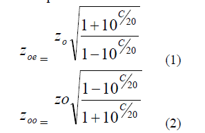 |
| Where C forward coupling requirement and is given in decibels. |
| Step 2 -Find Physical Dimensions w/ h and s / h |
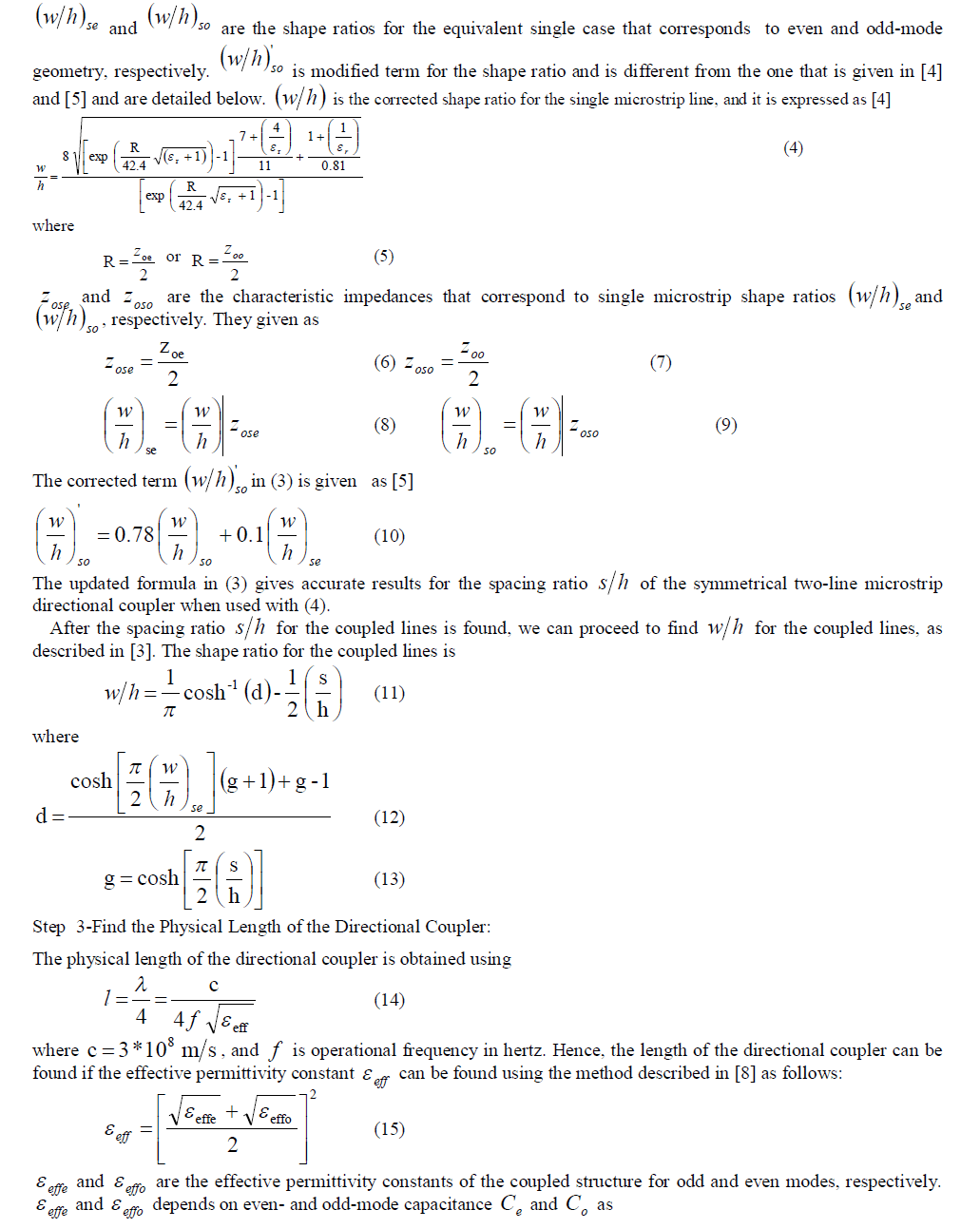
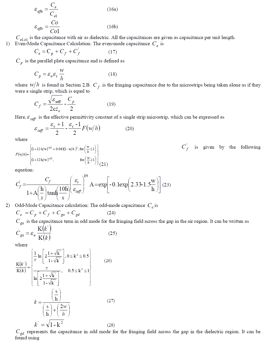
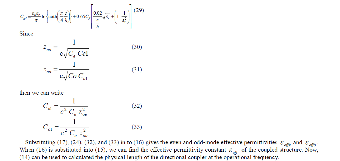
| The physical dimensions of the directional coupler are found using the synthesis method proposed in [3] and applying the corrections given in [4] and [5]. When the corrections are employed, we get the following equation for the spacing ratio s / h of the coupler in Fig.1: |
 |
 |
 |
 |
 |
 |
III. DESIGN CHARTS
|
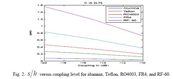
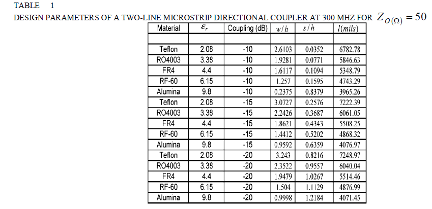
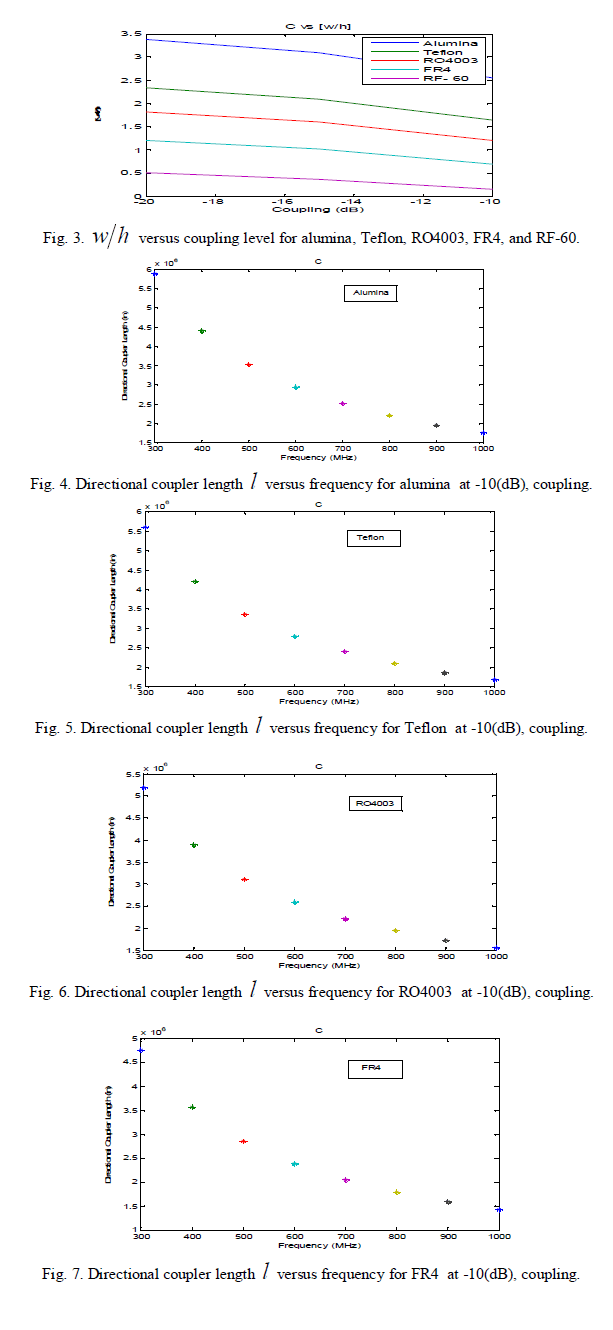
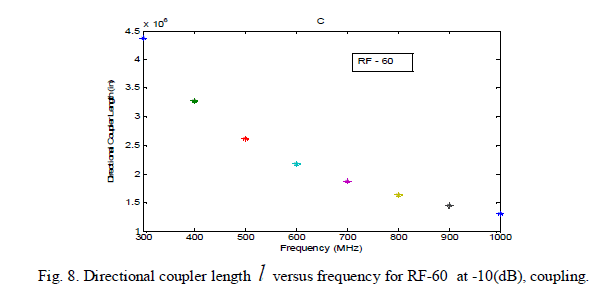
| In this section, we give the design charts to obtain a complete design for a two-line symmetrical microstrip directional coupler for the following five different materials: 1) alumina; 2) Teflon; 3) RO4003; 4) FR4; 5) RF-60. Fig. 2 gives the spacing ratio s h of the directional coupler versus different coupling levels. Fig. 3 gives the shape ratio of the directional coupler w h versus different coupling levels. Fig. 4-8 give the physical length l of the directional coupler versus frequency at different coupling levels for -10dB. |
 |
 |
IV.CONCLUSION
|
| In this paper, a practical and complete method to have a symmetrical two-line microstrip directional coupler has been presented by analytically introducing a three-step design procedure. Our design procedure requires knowledge of the port termination impedances, the coupling level, and the operational frequency, which are the three parameters that are known at the beginning of the design in practice. The design charts that give the shape and spacing ratios versus different coupling levels for five different materials that have relative permittivities between 2.08 ≤ r εr ≤ 9.8 are presented. We also give design charts that show the physical length of the directional coupler versus frequency at different coupling levels for the five materials. |
References
|
- Abdullah Eroglu, and Jay Kyoon Lee, “The Complete Design of Microstrip Directional Couplers Using the Synthesis Technique” IEEETransaction on instrumentation and measurement, vol.57, no.12, December. 2008.
- T.G.Bryant and J.A.Weiss, “Parameters of microstrip transmission lines and coupled pairs of microstrip lines,” IEEE Trans. Microw. TheoryTech., vol. MTT-16, no.12, pp.1021-1027, Dec. 1968.
- M.Kirschning and R.H.Jansen, “Accurate wide-range design equations for the frequency-dependent characteristic of parallel coupled microstriplines,”IEEE Trans. Mirow. Theory Tech., vol. MTT-32, no.1, pp. 83-90. Jan. 1984.
- S.Akhtarzad, T.R.Rowwbotham, and P.B.Jones, “The design of coupled microstrip lines,” IEEE Trans. Microw. Theory Tech., vol. MTT-23,no.6, pp. 486-492, Jun. 1975.
- J.J.Hinton, “On design of coupled microstrip lines,” IEEE Trans. Microw. Theory Tech., vol. MTT-28, no. 3, p. 272, mar. 1980.
- K.C.Gupta, R.Garg, and R.Chadha, Computer-aided Design of Microwave circuits. Norwood, MA: Artech House, 1981, ch. 3
- A.Eroglu, “Practical design of microstrip directional couplers,” in proc. IEEE AP-S, Jul. 9-14, 2006, pp. 849-852.
- I.Bhal, Lumped Elements for RF and Microwave circuits. Norwood, MA: Artech House, 2003.
- Dielectric Constant Reference Guide. online].Available:htpp://clippercontrols.com/info/dielectric_constants.html
- Mat lab version 7.1.
- “Transimmision lines properties of a strip on a dielectric sheet on a plane,” IEEE Trans. Microwave Theory Tech., vol. MTT-25, pp. 631-647,Aug. 1977.
- H.A.Wheeler, “Transmission-line properties of parallel strips separated by dielectric sheet,” IEEE Trans. Microwave Theory Tech., vol. MTT-13, pp. 172-185, mar. 1965.
- G.Policky and H.L. Stover, “parallel-coupled lines on microstrip,”Texas instruments, inc, Rept. 03-67-61.
- “Characteristics of coupled microstrip lines,” RCA Rev., vol. 31, pp. 479-498, sept. 1970.
|