ISSN ONLINE(2278-8875) PRINT (2320-3765)
ISSN ONLINE(2278-8875) PRINT (2320-3765)
| Elhaini Jamila, Saka Abdelmjid Mechanical Engineering Laboratory, Faculty of Sciences and Technology FST, Road Immouzer, B.P. 2202, Fez, Morocco |
| Related article at Pubmed, Scholar Google |
Visit for more related articles at International Journal of Advanced Research in Electrical, Electronics and Instrumentation Engineering
The use of solar energy in isolated sites is very useful and advantageous because of being simple and a safe way to supply energy. And like all physical systems, the modeling is an efficient way to optimize and manage the solar panel system. This is way this paper is focused firstly at presenting a state of the art of the model based design approach and especially the physical network approach. Also, it aims at dimensioning and modeling in Matlab/Simscape, a solar system intended to feed a domestic charge located in Morocco
Keywords |
| Solar energy system, Model based design, Physical network approach, Simscape |
INTRODUCTION |
| Solar or photovoltaic energy is increasily used. This type of energy is not only free and sustainable, but also clean for environment. Moreover, the solar energy system has the ability to cover a significant portion of energy demand especialy in remote areas not- connected to the power grid. |
| Modeling of such system is crucial in order to optimize and manage the photovoltaic generators which reduces costs and development time and increases the efficiency. |
| In this article, firstly, we present the state of the art of Model-Based-design approach and especially, we focus on Physical Network approach. According to this approach, each system is represented as consisting of functional elements that interact with each other by exchanging energy through their ports. Secondly, the solar energy system is introduced. The systme feeds o domestic house in Tetouan Morocco. In the third part, the system dimensionning is presented. Finally, we model this system in MATLAB/Simscape software a powerful tool for physical modeling which enables modeling the hole system in a single environment. |
RELATED WORK |
| Nowadays, the physical network approach is gaining popularity. Popinchalk [5] and Miller [6] discuss the advantages of the modelling based on this approach deemed to have the same benefits of the Kirchhoff’s laws. Unlike Salmi [18], which models the solar cell based on signal modelling, Venkateswarlu [13] presents a physical model based on Simscape language. |
| Heitz [20] presents the dimensioning method of a solar cell feeding a certain load. But here in this paper, what is new is that the model of the whole solar panel feeding a domestic house in Simscape is developed. |
MODEL BASED DESIGN-STATE OF THE ART |
| In traditional design processes, design information is communicated and managed as text based documentation. Frequently this documentation is difficult to comprehend. |
| Model-based design can be used as a specification that contains greater detail than text-based specifications. In realtime applications, it enables developers to evaluate multiple options, predict systems performance, test systems functionality by imposing I/O conditions that might be operationally expected (before product deployment), and test designs. It allows to build virtual prototypes or model to converge to an optimal solution much faster than traditional methods. |
| Modeling system can be done in different ways. Firstly, a mathematical model can be developed from natural laws that describe the evolution of the system. Then it is either linearized to form a transfer function or represented directly using block diagram and the signals are transmitted through the relationship between the individual blocks; the signals are used to transfer the values of individual variables from the output of an input block to other blocks. The mathematical model is dependent upon location in system making it difficult to reuse [1][2]. It is the input-output or signal-based methods which were useful for control engineers because they were written in a language they could easily understand and integrated with their control system models[5]. The models built by this method typically execute very quickly because the modeler has specified the exact calculations that the solver must complete[6]. |
| However, while this method works very well for control systems, it has some disadvantages when modeling physical systems. Physical systems are often expressed in the form of DAEs, which are composed of sets of equations that must be solved simultaneously. Another disadvantage is that the models that are created depend upon which elements they are connected to. It is necessary to know which inputs are available and which outputs must be calculated in order to connect it with the rest of the system. This type of model is difficult to reuse in other models or applications, for it requires that the other components in the system are modeled in the same manner. This becomes especially complex when modeling components that cross multiple physical domains, like a DC motor or a hydraulic cylinder[5]. |
| Due to these reasons, engineers began looking for a better method for modeling these types of systems. For purely electrical systems, KirchoffâÃâ¬ÃŸs laws have been used for quite a long time to express the equations for a entire system by applying a few basic mathematical rules to a network of electrical components represented by their individual mathematical models [7]. For example, the component model of a resistor was represented by v=iR, and this component model of an ideal resistor was identical for all resistors in the electrical network, independent of where the resistors were placed in the circuit. The equations for the entire system could be derived by applying KirchoffâÃâ¬ÃŸs laws at the nodes of the electrical circuit. This method permits the component models to be modular and reusable while also being able to mathematically represent an entire circuit [5].It was seen that other physical domains were analogous to electrical networks, and that similar rules could be applied to systems composed of one or more other physical domains. |
| Recently, the new approach, Physical Network provides for multidomain physical systems the same benefits that Kirchoff’s laws provided for electrical systems. Using this method, an engineer could build up a library of component models that could be reused in a variety of models in a variety of applications which facilitate multidomains modeling. |
| Languages such as Simscape [8] and Modelica [9] are based on physical this approach. |
| We focus in this work in Simscape language, it has no need for co-simulation environment. |
STRATEGY BASED ON SIMSCAPE MODELING LANGUAGE |
| Simscape is a toolbox for physical modeling developed by the MathWorks for Simulink, and it has been available since version R2007A of the MATLAB suite [4]. It includes a foundation library, which contains basic components for electrical, hydraulic, mechanical and thermal systems, and an utilities library [3]. |
| There are also more specialized toolboxes for physical modeling (such as SimDriveline, SimHydraulics, SimElectronics and SimMechanics) that now are considered as parts of the Simscape product family. |
| In R2008b, a major upgrade of Simscape was made, introducing the Simscape language which allows the users to create their own physical models, and even new physical domains. The language is based on MATLAB syntax, but it is possible to define acausal equations [4]. This language offers three important advances: non-causal modeling based on differential and algebraic equations instead of assignment statements, multidomain modeling and object-oriented modeling which enables the reuse of the model [10]. |
| In Simscape each block in the system consists of functional elements that interact with each other by exchanging power or energy trough their ports. These ports, named physical conserving ports, are bidirectional and each different type of ports represents a physical domain. We can only connect to conserving ports of the same type. There are several types of conserving ports in SIMSCAPE, each with effort and flow associated variables [10]. |
| The lines between these ports carry physical variables (through and across) instead of signals. Through variables are measured with a gauge connected in series to an element. While Across variables are measured with a gauge connected in parallel to an element [11]. |
| The product of these variables represents the power (energy flow) in watts, with the exception of air and magnetic field, where their product is energy [12]. |
SOLAR ENERGY SYSTEM |
| Solar system energy is the most important renewable and sustainable energy system. Solar-electric-energy system has grown consistently and become a popular resource of energy. The main reasons for this huge attention are; 1) increase in efficiency of solar cells; 2) recent technological improvements; 3) green and environmental friendship [13]. |
| A. Principle of a photovoltaic cell |
| Photovoltaic panel or solar panel systems capture the sun’s energy using photovoltaic cells. |
| The photovoltaic cell is a sensor consisting of a semiconductor material absorbing light energy and transforming it into electrical current. The principle of operation of this cell uses the properties of light absorption by the semiconductor materials. |
| The photovoltaic cell is a sensor consisting of a semiconductor material absorbing light energy and transforming it into electrical current. The principle of operation of this cell uses the properties of light absorption by the semiconductor materials. |
| B. Solar/photovoltaic cell model: |
| A ready to use block in SimElectronics solar cell shown in fig 1 bellow, is formed from a single solar cell as a resistances Rs connected in series with a parallel combination of a current source, two exponential diodes and a parallel resistor Rp [13], [15], [16] (as shown in fig 2 bellow).The output current I is given by the equation (1). |
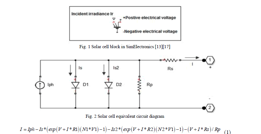 |
| In this equation, Iph is the photocurrent, Is is the reverse saturation current of the diode, q is the electron charge, V is the voltage across the diode, K is the Boltzmann's constant, T is the junction temperature, N is the ideality factor of the diode, and Rs and Rsh are the series and shunt resistors of the cell, respectively [18]. |
| C. Connecting Multiple Solar cells |
| There are 3 ways to connect solar panels: parallel, series, and a combination of both. |
| To increase the current, you can connect pairs of panels in parallel. In this case, all the positive terminals of the cells are connected together as are all the negative terminals. |
| To increase the voltage, you can connect pairs of panels in series by connecting the positive terminal of one panel to the negative of the next. |
| To increase both the current and the voltage we use the two types of combination. |
| D. Battery |
| Because the renewable energy source is intermittent, it is necessary to store it for times of low or no renewable energy production. |
| There are many types of energy storage. The most common is the batteries which store electricity in a chemical form. |
| There are many brands and types of batteries. Currently, Lead-Acid batteries offer one of the best compromise between cost and usable service rendered. |
DIMENSIONING THE SOALR PANEL FEEDING A DOMESTIC LOAD |
| A. Implantation site |
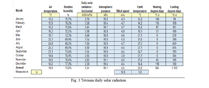
| The site chosen is in Tetouan/Morocco city. |
| The climate data of this site (shown in fig 3) which is the NASA data is obtained from Retscreen software [19]. |
 |
| B. Calculating domestic consumption |
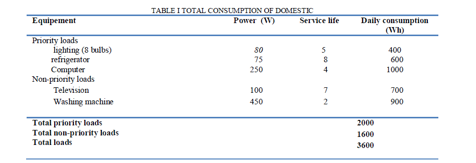
| The first step in designing is to find out the total power of all loads that need to be supplied by the solar system. Our system is supposed to supply a domestic house not connected to the power grid and equipped with required household appliances. |
| The estimation of the daily energetic needs is presented in the TABLE I below. |
 |
| C. Dimensioning of the photovoltaic panel |
| To find out the sizing of photovoltaic module, the total peak watt produced is needed. To obtain the total peak watt, we divide the total loads needed from the photovoltaic panels by a coefficient called panel generation factor. |
| This factor is different from one location to another since it depends upon the climate of the site. For Morocco, the panel generation factor is 4. |
| So, for our study, the size of the photovoltaic panel is 900 peak watts. |
| The number of cells in series n is obtained by dividing the module voltage by the cell voltage [20]. In our case, n=24/0.5. |
| The number of cells in parallel m is equal to the module current divided by the cell current [20]. The module current is equal to the total power divided by module voltage that is to say: 3600/24. |
| Then, the number of cells is 14400 and the module surface is 36 m². |
| D. Battery dimensioning |
| The battery should be large enough to store sufficient energy to operate the equipments when there is no power produced by the solar system at night and cloudy days |
| To size the battery, the calculation of the battery ampere-hour capacity factor is needed. This is obtained from the following equation 2: |
| 0.8 is the value of the depth of discharge. Then, our battery has the capacity of 562.5 Ah rated at 24V for 3 day autonomy. |
PHYSICAL MODELING OF SOLAR PANEL IN SIMSCPE |
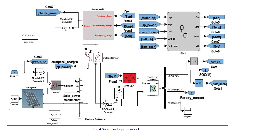
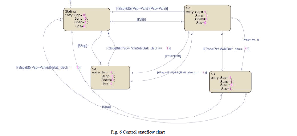
| In the fig 4 bellow, the solar panel feeds a variable charge and the excess of the produced energy is stores in the battery. The protection of the battery against overcharge and deep discharge and varying the charge value are provided by the flowchart developed in Stateflow/Matlab toolbox (fig 6). |
 |
| A. Photovoltaic panels model |
| The solar panel modeled in the fig 4 above, is obtained by interconnecting in series and in parallel the solar cell block available in SIMELECTRONICS. We have 14400 solar cells. |
| B. Charges model |
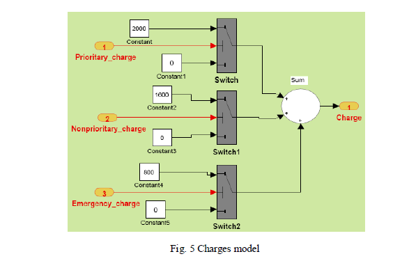
| As shown in fig 5 bellow, the charges are divided in three types: |
| • Priority charges which must not be triggered unless there is no energy production |
| • Non priority charges: when the energy production is lower than the loads consumption, an unballasting of these charges is made to avoid tripping the circuit breaker on all loads. |
| • Emergency charges which must be switched on when there is an overproduction and the battery is totally charged. |
 |
| C. Stateflow chart |
 |
| In the fig 6 above: |
| Scp is the priority charges switch, Scnp is the non priority charges switch, Scs is the emergency charge switch and Sbat is the battery switch. |
| If the system is on, and the power produced (Psp) is greater than the charge power (Pch), all loads are fed except the emergency one which is switched on if the battery is charged (Batt_ch is true). |
| The non-priority charges are switched off if the power produced is less than the total charges consumption and the battery is discharged (Batt_dech is on). |
| In order to protect the battery against deep discharging, we switch it off if the SOC is less than or equal to 20%. |
SIMULATION RESULTS AND DISCUSSION |
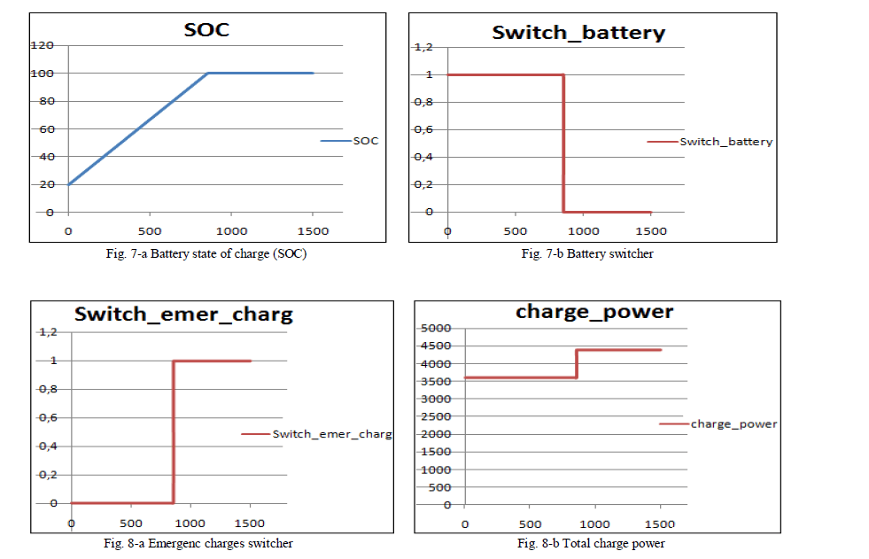
| For a solar irradiation of 5000W/m2/d, the battery is totally charged at time 845s as shown in fig 7-a bellow. In this time, the battery is switched off (as shown in fig 7-b bellow) and the emergency charge is switched on (fig 8-a bellow). So the total charges passes from the value 3600 to 4400 (fig 8-b). |
 |
CONCLUSION |
| In our work, we had present the state of the art of the physical network approach, a more developed method for multiphysics and multidomain modelling than the classical method of mathematic-physical analysis. This method enables modelling realistic models and facilitates the reuse of these models. |
| Also, we were able to model the solar panel system feeding a domestic load and simulate this model in MATLAB / SIMSCAPE, a powerful tool for modelling physical systems. |
| Also, the results prove that it is possible to build and simulate physical models with Simscape software. |
| My suggestions for further works would be the following: |
| 1. Enrich the Simscape’s library with more blocks which cover more physical domains |
| 2. Build a more realistic and complex solar panel model which can rotate in order to be horizontal to daily irradiation. |
Tables at a glance |
References |
|