Keywords
|
| Rotor position, mathematical model, fuzzy logic, PID. |
INTRODUCTION
|
| Stepping motor is widely used in electrical and mechanical applications where torque at low speed, positioning accuracy, and high speed dynamic are determining factors. It can, thus, be found in numerous applications. For example in medical applications such as, accurate dosage with peristaltic pumps or pipettes and motion control in dialysis equipment. Also, in automotives the internal combustion engines contain several systems to control emissions and reduce NOx level. These systems always combine a stepper motor that drives efficiently integrated valves. In telecommunications, the stepper motor is used to actuate antennas and combiners to desired position. All these type of applications require a robust actuator that can withstand vibrations and must respond quickly and precisely to a signal position, also at the same time it should overcome a dynamic torque load. The stepping motor has the advantage over other kinds of motors because it works well in open loop since it carries out motion step by step when voltage impulses are applied to its phases. But, due to its inertia, the rotor oscillates around the final position before settling to final position. In addition to this the motor can lose steps if the variation of the load torque is fast. |
| The use of new programmable architecture like field-programmable gate arrays (FPGA) circuit allows us to get the micro-step movements. This smoothes the movement for rotor but leaves the open-loop control problem unsolved. To solve this problem, it is necessary to introduce a closed loop control technique to improve the performance of the motor and the robustness of the control. A first kind of solution was the introduction of mechanical sensors. This solution increases the size and the cost of the system so system becomes bulky. Furthermore from the analysis of past experience from automotive applications shows that mechanical measurement for position or speed suffers in hightemperature and high-vibration environment. Due to these limitations introduction of mechanical sensor is not suitable for this type of system. Hence the sensor-less control technique emerges. The digital closed loop principle was introduced for the position control by Fredriksen, Kuo and Takashi in the years 1969, 1970 and 1984 respectively. They used the closed loop algorithm in order to improve the stepping motor positioning accuracy. The use of selftuning regulator to control the stepper motor speed was introduced by Betin et al. The purpose of the self tuning regulator is to force the controller to adapt the motor operating conditions. But, this kind of control technique is difficult to be implemented in real time because it requires a large amount of floating-point computation, so the sampling period also gets increased. |
| This paper presents an application of sensor-less drive technology to a stepping motor drive system. The drive system is characterized by sensor-less detection of position of rotor and for this switching of the switches is controlled with help of switching frequency. As a result, the drive system can damp rotor natural vibration of the stepping motor and Desired position can be achieved. |
MATHMATICAL MODEL AND ASSUMPTIONS
|
| The motor considered in this paper is a two phases stepping motor and assumptions for the motor parameters is as follows. |
| 1. Uniform air gap is present and poles are non salient poles. |
| 2. Distribution of flux is sinusoidal. |
| 3. Losses or iron and saturation is negligible. |
| 4. Self inductance of windings is constant. |
| According to above assumptions, the mathematical model of the two- phase stepping motor is shown below in Fig.1. |
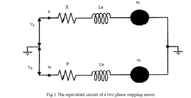 |
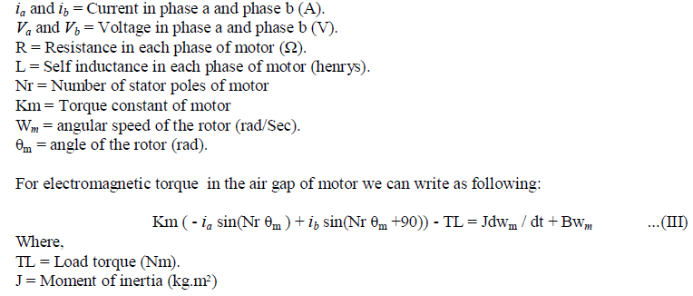
| The stepping motor can be described with the help of differential equations. |
 |
| Where, |
 |
 |
FUZZY LOGIC CONTROLLER
|
| In a fuzzy logic controller usually the control signal is generated with the help of knowledge-base and a fuzzy logic inference mechanism with the system. The knowledge-base consists of a defined series of if..then type of rules. The four principal components of a fuzzy logic controller can be given as: |
| 1. Fuzzification interface. |
| 2. Knowledge-base. |
| 3. Decision-making logic. |
| 4. Defuzzification interface. |
| Fig.2 shows the principal elements of a fuzzy logic controller. |
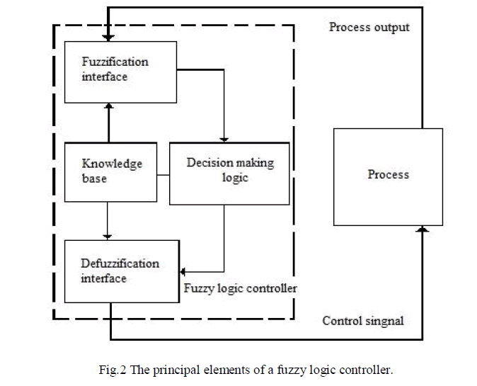 |
| Each block in fuzzy controller performs specific functions. Output from process is taken which is usually set of data this data needs to be fuzzified for further processing so the fuzzification interface is used for this purpose. Knowledge base and decision making logic works together to calculate required control action to get the desired output from the system. The control signal of fuzzy logic controller needs to be converted back to normal form so for that defuzzification interface is used. |
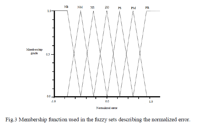 |
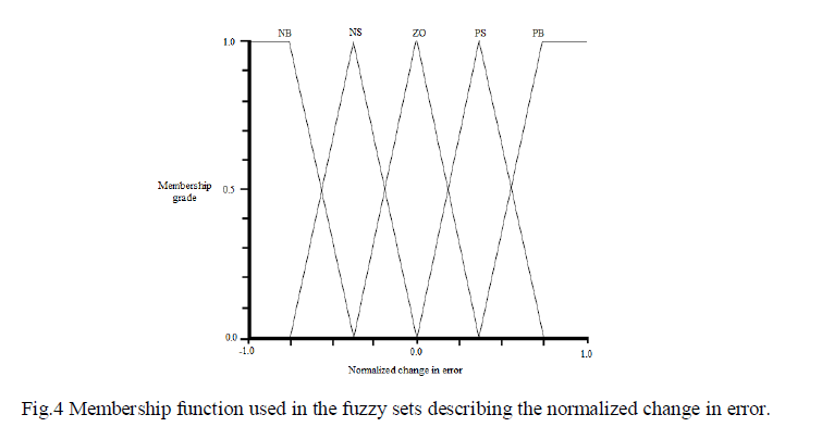
| For the process of fuzzyfication here triangular membership functions are used (see Fig.3 and Fig 4). In this type of membership function used there is mapping of the input variable value to the fuzzy logic controller value and every input label. These functions specify the membership function that corresponds to the input variable value in the different fuzzy sets defined by the input labels. For membership function specification [0,1] interval is used, and for membership functions normalization [-1, 1] interval is used .It is important to note that every function has its own Scaling Factor and if the Scaling Factor is modified the corresponding mapping changes, so the membership function distribution is modified . |
 |
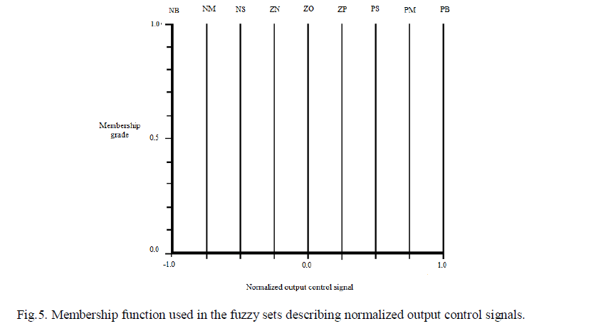
| For the defuzzification process only a singleton membership function was used for the two output linguistic variables. This function is also normalized into the interval [-1, 1]. Fig.5 shows an example of the kind of function used. |
 |
| The Rule-Base is specified in Table 1. These rules were created using previous information of the stepping motors dynamics, principally the rotor position characteristics. This rule base will be help in taking decisions according to the situation of the system. Every time error and the change in error of the system is taken into account and the particular rule will be used for controlling purpose so as to achieve desired position of the motor shaft. |
| The rule base for the fuzzy logic controller is given below. |
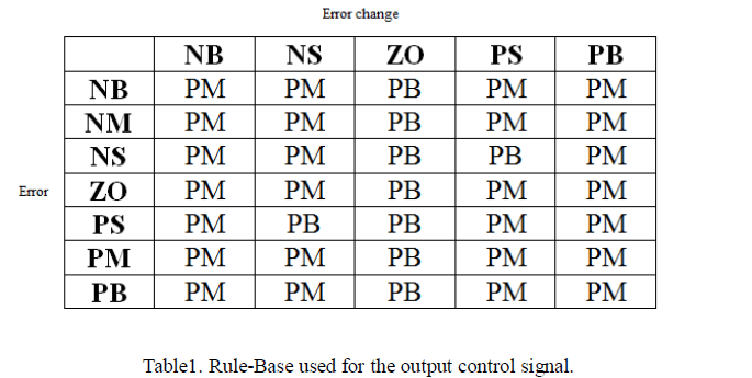 |
| ( NB = negative big, NM = negative medium, NS = negative small, ZN = negative zero, ZO = zero, ZP = positive zero, PS = positive small, PM = positive medium, PB = positive big ) |
THE FUZZY-PID CONTROLLER AND MATLAB\SIMULINK MODEL
|
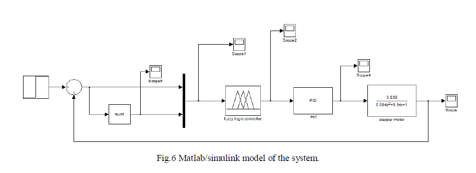
| Now a days because of the simplicity of operation, ease of design and high robustness the conventional proportional– integral–derivative (PID) controllers used most extensively in the industries for controlling the processes. As for nonlinear systems, higher order and time-delayed linear systems, and particularly complex systems that have no precise mathematical models, fuzzy logic controller is not depended on mathematical models and is one of promising control technique used for current applications. As it is difficult to obtain the mathematical models for tracking system, and to get high tracking precision the fuzzy logic controller and PID control is used together. |
| The MATLAB\simulink model of the system is obtained and shown below. |
 |
RESULTS AND ANALYSIS
|
| Above model is used for the simulation purpose. Here the input signal given to the system is the step-function signal with the amplitude of 1, and the sampling time is 1ms.At particular time the disturbance with its amplitude of 1 is applied to controller. From this model following results are obtained. The output results of this simulation are shown below. |
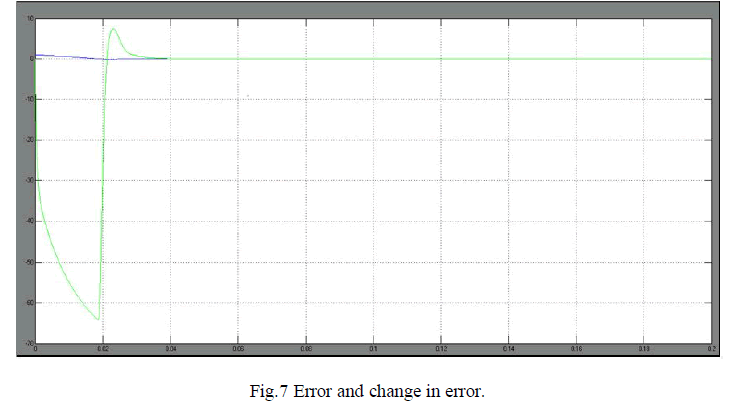 |
| The output in fig.7 shows the error and the change in error. Here X-axis denotes the time and Y-axis denotes the error amplitude. Here the change in error may be high or low. According to this error fuzzy logic controller with PID will try to suppress the error in the system. |
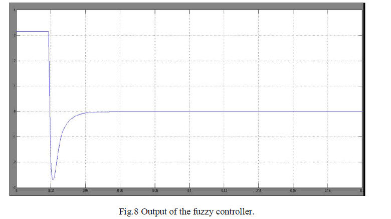 |
| Fig. 8 shows how the output of fuzzy controller is changing with respect to time. Here X-axis denotes the time and Yaxis denotes the amplitude of the output. When error changes with respect to time then output of the fuzzy controller changes rapidly so as to suppress error. Initially output of the controller is high but after particular time it gets reduced and settles near to zero value. |
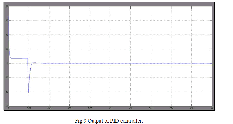 |
| Proportional-integral-derivative (PID) parameters will get changed according to change in error so initially when error is high the control action required to minimize the error is also high (see Fig.9) as the controller minimizes the error so the control action also get minimized and get settled near zero value. |
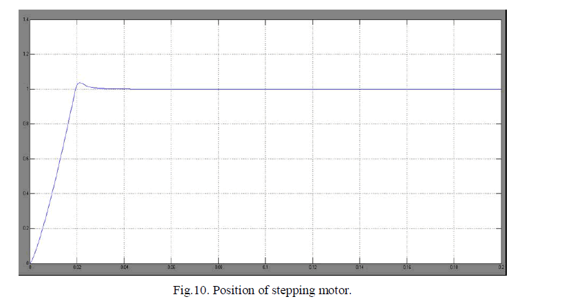 |
| Finally with the help of fuzzy logic controller and PID the desired position of stepping motor can be achieved (see Fig.10).Initially the response shows the overshoots and in some cases it can be oscillatory. But the controller minimizes the error and position gets settled to desired value. |
CONCLUSION
|
| In this work the fuzzy logic controller with PID is used to improve the system response and with the help of simulation is can be seen that the single step position response of the stepping motor is improved with this control technique. For this simulation is done in MATLAB/simulink. Result shows that how error changes with time and to minimize the error controller takes proper control action. The settling time and overshoot is also reduced. So the desired position of stepping motor can be achieved using this control technique. |
ACKNOWLEDGMENT
|
| I would like to thank Mr. J Sam Jeba Kumar, Asst. Professor, department Of ICE at SRM University for supporting me in direct or indirect means. |
References
|
- . Li Zheng, Yamatake-Honeywell , "A practical Guide to Tune of Proportional and Integral (PI) Like Fuzzy Controllers" in Co. Proc. of IEEEInter. Conf. on Fuzzy Systems. 633-640, 1992.
- . T. Yano, T. Suzuki, M. Sonoda and M. Kaneko, “Basic characteristics of the developed spherical stepping motor”. Proc. of InternationalConference on Intelligent Robots and Systems, kyongyu, Korea 1999 1393–1398.
- . P.P. Acarnley. “Stepping Motors: a guide to modern theory and practice” Peter Peregrinus, London 159, 1984.
- . R. Yager and P. Filev. “Essentials of Fuzzy Modeling and Control “John Wiley & Sons, New York 383, 1994.
- . T. R. Fredriksen, “Application of the closed-loop stepping motor”, IEEE Trans. Automat. Contr., vol. AC-13, pp. 464-474, Oct. 1968
- . B. C. Kuo, “Closed-loop and speed control of step motors”, 3rd Annu. Symp. Incremental Motion Control Systems and Devices, Urbana-Champaign, IL, May 6–8, 1974.
- . F. Betin, M. Deloizy, and C. Goeldel, “Closed loop control of stepping motor drive: Comparison between PID control, self tuning regulationand fuzzy logic control”, Eur. Power Electron. J., vol. 8, no. 1-2, pp. 33-39, June 1999.
- . Takashi Kenjo, “Stepping motors and their microprocessor control”, Oxford University Press, 1984.
- . Chuen Chien Lee. "Fuzzy Logic in Control Systems: Fuzzy Logic Controller - Part I", IEEE Trans. on Systems, Man, and Cyber, 20, (2), 404 -418 (1990).
|