ISSN ONLINE(2278-8875) PRINT (2320-3765)

All submissions of the EM system will be redirected to Online Manuscript Submission System. Authors are requested to submit articles directly to Online Manuscript Submission System of respective journal.

Position Sensorless Control of BLDCM Using Direct Torque Control

Dolly Nelson1, Jayasri R. Nair 2
  1. PG Scholar, Dept. of Electrical and Electronics Engineering, Rajagiri School of Engineering and Technology, Kerala, India
  2. HOD, Dept. of Electrical and Electronics Engineering, Rajagiri School of Engineering and Technology, Kerala, India
Related article at Pubmed, Scholar Google

Visit for more related articles at International Journal of Advanced Research in Electrical, Electronics and Instrumentation Engineering

Abstract

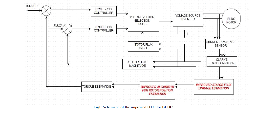
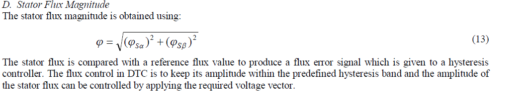
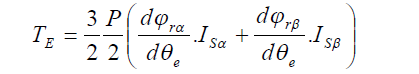
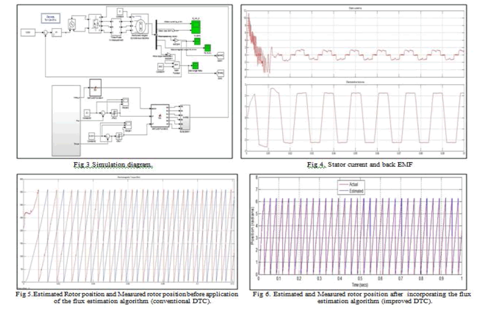
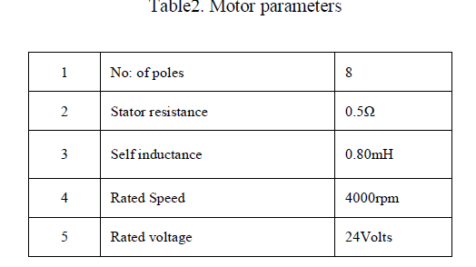
In this paper, speed and position sensorless control of BLDC motor with non sinusoidal back EMF using direct torque control with an improved flux estimation algorithm has been proposed. The rotor position is obtained through calculations by generating an orthogonal flux system. PI controllers are used for tuning. The inverter voltage space vector for a two-phase conduction mode is derived from a simple look-up table to obtain the desired quasi-square wave current. The output of the hysteresis controller is fed to the look-up table. The look-up table includes input information from torque, flux and sector to produce the corresponding switching pulses for the inverter. This simplifies the switching and decreases the processing time, unlike the PWM or Space vector PWM controls. It gives faster torque and speed response with reduced ripples. It also provides an accurate speed control. The proposed method closely resembles the DTC used in ac sinusoidal motors but differs in its flux estimation algorithm. This methodology improves the efficiency of the drive. The validity and practical application of the proposed two-phase conduction DTC of BLDC motor drive scheme is verified through simulations on a 24V 4000rpm PMBLDC motor.

Keywords

Permanent Magnet Brushless DC Motor; Direct Torque Control; Flux Estimation; Position Sensorless.

INTRODUCTION

In recent years, BLDC motors are being extensively used not only in industrial or servo applications but also in several household electrical appliances. This increased demand for BLDC motor is due to its high efficiency and high torque to weight ratio. BLDC motors are synchronous motors which have permanent magnets placed on the rotor and armature windings on the stator, with trapezoidal back-EMF. BLDC motors offer higher reliability due to the elimination of brushes and reducing frequent maintenance and wear and tear. It also helps to avoid limitations in its current ratings and output capability. Losses due to arcing are also reduced. BLDC motors are electronically commutated using solid state switches. The process of commutation creates trapezoidal waveforms by turning off current in one phase and simultaneously switching it to another phase. For smooth torque waveforms, quasi square wave currents are given to the stator windings. The knowledge of rotor position is essential to determine the next coil that has to be energized. [1] Hall sensors and encoders are used for this purpose. However position sensors like encoders and resolvers increase the cost and complexity of the system. To reduce the cost as well as its complexity, the sensorless strategy is proposed, where algebraic equations are used to calculate the flux linkage using the motor parameters and the voltage/current measurements. There are several sensorless strategies which include, back EMF method and third harmonic sensing method, of which the most widely used method, is the detection of zero crossing point. While using BLDC motors, the primary concern with regard to industrial applications, is to obtain a low frequency ripple free torque.
Field oriented control and DTC are two popularly used control methodologies used for high performance applications in AC drives. FOC was introduced by Hasse, Blaske [2] and Leonhard. It is based on the decoupling of the flux producing component and torque producing component of stator current. Field producing component is aligned along the rotor flux linkage vector and hence the name FOC. In mid 1980s the DTC scheme for induction motor was
image
introduced by Takahashi and Noguchi [3] in Japan and by Depenbrock [4] in Germany. Later on DTC techniques for surface mounted and interior PMSM were analyzed [5]. In [6] and [7] the conventional DTC scheme was applied to BLDC motors. The voltage space vector for a two phase conduction mode is defined and the electromagnetic torque equation is derived from the stationary reference frame. In [7] only the electromagnetic torque can be controlled using DTC. A complete characterization of the class of feedback controllers which produce ripple free torque in BLDC motors was explicitly analyzed [8]. It is a combination of single perturbation technique and feedback linearization technique. An optimal torque control was presented by Aghili [9] based on quadratic programming for general multiphase BLDC motors. Copper losses and torque ripples and power dissipation were minimized using equality and inequality constraints via Kuhn-Tucker theorem but phase current saturation and flux weakening performance was not explained. An expensive experimental setup is required with hydraulic dynamometer, high resolution encoder and torque transducer. In [10] a direct torque control for permanent magnet AC motors using state feedback input-output linearization technique. Due to calculation complexity this method limits the Fourier coefficients to an arbitrary high harmonic order. The disadvantages in [10] are improved in [11] by using a model reference adaptive system where the torque is calculated from the estimated flux and measured current. Here torque is controlled using an integral variable structure control and space vector PWM. This increases the complexity of the system. But parameter sensitivity is a concern as the variations in resistance and inductance have a degrading effect on the control performance. [12] Presents a novel optimal current excitation scheme based on d-q reference frame by elimination of torque ripple. Several transformations are required which complicate the control algorithm. This scheme does not control the torque directly and so fast torque response is not possible. [13] Involves multiple reference frames and tedious algorithms, increasing the complexity of the system. This study presents a speed and position sensorless control of BLDC motor with non sinusoidal back EMF using direct torque control with an improved flux estimation algorithm. Here both torque and flux are controlled simultaneously. This method has advantages such as fast torque response as compared to the field oriented control method. PWM strategies are not used, also park transform, inverse park and inverse clark’s are not used thereby making the control simpler. This drive uses the two phase conduction mode by estimating the rotor position. A hysteresis controller is used for flux and torque control and the MOSFET switches are used for on-off operation. The electromagnetic torque and flux are directly and independently controlled using six voltage space vectors defined in the look-up table.

PROPOSED SYSTEM

A. Principles of the proposed system
The improved direct torque control algorithm for BLDC drive has been proposed since it has all the advantages of conventional DTC and also has the potential to reduce the drawbacks of the conventional DTC system. The schematic of the proposed system is shown in Fig1. The voltage vectors for this DTC method is directly controlled from a simple look-up table. In the BLDC motor the stator voltage equations referred to the stationary reference frame αβ are similar to that of PMSM motor. The three phase voltages in abc coordinates are sensed and transferred to αβ using Clarke’s transformation.
image
image
image
Here Va,Vb, Vc and Ia, Ib, Ic are the three phase voltages and currents respectively. Vsα, Vsβ, Isα, Isβ, φsα, φsβ, φrα and φrβ are the stationary reference frame components of terminal voltage, stator currents, stator flux linkage and rotor flux linkage. Rs and Ls represent the phase resistance and phase inductance. Vcomp is the compensating voltage used for rotor position correction. Kp and Ki are the propotional and integral quantities of the PI controller.
C. Position Estimator
The rotor position (θe) is estimated from the permanent magnet (PM) flux observer by generating an orthogonal flux system and by using the special trigonometric function atan2.
image
image
image
E. Torque Estimation
The electromagnetic torque in the stationary α-β reference frame for a non-salient pole brushless machine with non sinusoidal stator flux linkages is given as,
image
Where P is the number of poles and θe is the electrical angle. The electromagnetic torque is compared with a reference torque to produce an error signal which is given to the hysteresis controller.
F. Vector Selection Table
The voltage vector plane is divided into six sectors. In each sector, six non-zero voltage vectors are used. In the DTC of BLDC, application of the zero voltage vectors is not the same as in induction machines because the stator flux linkage will change when the zero voltage vectors are selected. Hence, zero voltage vectors are not considered in controlling the stator flux linkage in a BLDC system. Stator flux linkage should always be in motion with respect to the rotor flux linkage vector and the higher the stator vector rotation speed, faster the torque response. The possibilities are tabulated into a switching table in Table1. The torque and flux are obtained from the hysteresis controller and θ from the sector selection table.

SIMULATION RESULTS

The simulations of the closed loop modified DTC of BLDC motor was performed in MATLAB/Simulink as shown in Fig3. The motor parameters values used are shown in Table2. The stator current and back EMF of the three phases are phase shifted by 120 degrees. Reduced torque ripples and accurate speed control is achieved using this improved DTC.
image
image
image

CONCLUSION

A modified Direct torque control of BLDC motor with speed and position sensorless control with an improved flux estimation algorithm was proposed. The flux estimation helps to reduce the complexity of the system by eliminating the filters produced due to DC offsets in the integrator. Look-up table simplifies the switching and decreases the processing time unlike the PWM methods. Speed control is accurate with reduced transient time during speed change over. Speed control is done with the help of a PI controller. This speed control is possible for a load variation of 0-0.004Nm. The proposed system has been verified by MATLAB simulation and the results indicate that the intelligent controller can significantly reduce the torque pulsation to a great extent and improve the drive performance.

References