International Journal of Advanced Research in Electrical, Electronics and Instrumentation Engineering
ISSN ONLINE(2278-8875) PRINT (2320-3765)
ISSN ONLINE(2278-8875) PRINT (2320-3765)
PP.vinod Kumar1, L.Venkatasureshkumar2, Ravipudi.sudhir3
|
| Related article at Pubmed, Scholar Google |
Visit for more related articles at International Journal of Advanced Research in Electrical, Electronics and Instrumentation Engineering
At present days, wind energy is a very useful energy source. Then the wind power penetration is increasing, the improvements of the manufacturers in order to comply with the grid interconnection requirements. This paper focus on the maximization of the output power, and the generator side converter is controlled. Then the maximum power is obtained from the wind, and this is depending on the velocity of wind. The wind turbine grid side converter which let the full controllability of the active and the reactive power delivered to the grid. Modelling and simulation of the power control of grid connected PMSG wind energy system implemented by using MATLAB/ Simulink.
Keywords |
| wind turbine, PMSG, PI Controller, Back to back converter etc. |
I. INTRODUCTION |
| The renewable energy sources are mostly used in the world wise. The cost of oils is increasing day by day and fossil fuels are very less, and less solution is attracted. The wind energy is free and not pollution. The wind turbine transforms the wind energy into the mechanical energy and mechanical energy into the electrical energy it is also called generator. Although the advantages of wind turbines are simple, high efficiency, less cost, production maintenance is easy. Wind turbines [7] are two different types of speeds i.e Fixed speed, and variable speed, the PMSG is mostly depending on variable speed why because of efficiency is high and maximum power is obtained by the wind.Then fixed speed operation the efficiency is very less. The generator is directly connected to the back-to-back converter.The generator side converter is mainly used to control the generation of the speed and the output power is maximize at low wind speeds.The grid side converter is mainly used to dc link capacitor constant and reactive power delivered to the grid. |
II. WIND TURBINE |
| There are different winds turbines are currently in use: the fixed speed wind turbine with Squirrel Cage Induction Generator (IG), the variable speed wind turbine with Doubly Fed Induction Generator (DFIG), and the variable speed wind turbine with Permanent Magnet Synchronous Generator (PMSG) [1]. The manufactures are developing new larger wind turbines. The power of wind turbines built in 1980 was 50 kW and the diameter of rotor was 15 m long. In 2003 they had the power of 5 MW and the size of diameter of rotor was124m. The wind turbine transforms the wind energy into mechanical energy then the wind turbine of a rotor is by the various forces acting on the wind turbine of tower and on the blades (e.g. centrifugal, gravity and varying aerodynamic forces acting on blades, gyroscopic forces acting on the tower),then introducing the effects of mechanical the energy of influencing conversion. The mechanical effects have been modelled by eigenswings mainly due to the following phenomena: asymmetry in the turbine, vortex tower interaction, and mechanical eigenswings in the blades. The wind turbine designed to manufacture was low cost, and simple construction. Several countries has available wind speeds are very low, this turbines is used in several places why because maintenance is easy and generate power in wind speeds are very low in unsteady conditions. The turbines of benefits are existing structures can be mounted, therefore installation costs are lowering and tower structures are eliminating. The smaller turbines can be used for store energy for batteries, and grid power is eliminated. |
III. MODEL OF PMSG |
| The PMSG of model was developed by the dq synchronous reference frame, where q-axis is phase shifted of 90 degrees a head of the d-axis then depending on the direction of rotation. In order to simplify the system the generator was assumed to be a PMSG with surface mounted magnets then field currents are absent.The model of PMSG is given by the following equations. |
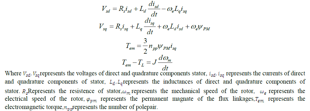 |
| The advantages of PMSG are high efficiency, easier controllability, smaller in size.then compared to the DFIG. The disadvantages of PMSG are fixed excitation. |
IV. BACK TO BACK POWER CONVERTER |
 |
| The above diagram is back to back converter [3].The power flow can be a bi-directional, either generator side or grid side. In the diagram generator side is AC is converted to the DC this is acts like as a rectifier. In the grid side DC is converted to the AC this is acts like as an inverter. Here DC link capacitor is constant. The capacitor acts like as a filter. This is eliminates the ripples of the harmonics. The back to back converter is widely used wind turbine applications. In the diagram two identical voltages sources and connected between the capacitor. |
V.PERTURB AND OBSERVEMPPT TECHNIQUE |
| There are different types of MPPT techniques are available, but in this project Perturb and Observe method is used. Perturb & Observe (P&O) is the simplest method. In this we use only one sensor, that is the voltage sensor, to sense the PV array voltage and so the cost of implementation is less and hence easy to implement. The time complexity of this algorithm is very less but on reaching very close to the MPP it doesn’t stop at the MPP and keeps on perturbing on both the directions. When this happens the algorithm has reached very close to the MPP and we can set an appropriate error limit or can use a wait function which ends up increasing the time complexity of the algorithm. |
VI.TRANSFORMER |
| The basic principal of transformer is faradays law of electromagnetic induction. Then the features of transformer are Constant frequency device, Constant power device, Electromagnetic energy conversion device, Complete transform, Transformer is a coupled circuit, Transformer is single excited device, Transformer is a phase shifting device, Transformer is a constant flux device, Transformer is a negative feedback circuit, Two port network. |
| Where two types of transformers i.e step up or step down transformers is used. Here step up transformer is used because of the level of voltage has to be increased connected in order to be a transmission line i.e. a transformer is used and it is connected to the pcc(point of common coupling). |
VII.BLOCK DIAGRAM OF PMSG |
 |
| In the above block diagram consisting of the wind is given to the wind turbine ,in the wind turbine gear box is available ,gear box and the PMSG is decoupled with a shaft. Then the wind turbine transforms wind energy into the mechanical energy.The mechanicalenergy is given to the PMSG then it is converted to the electrical energy,then electrical energy is given to the back toback converter.where filter is eliminates the harmonics.Then the transformer is the improves the level of voltages i.e is step up the voltages.where wind turbine controls the pitch angle control(β),the generator side converter controls the speed of the generator and the speed of the torque and maximum output power at low wind speeds.Then the grid side converter controls the dc-link capacitor constant and reactive power delivered to the grid. |
VIII.PI CONTROLLER |
 |
| The PI controller computes and transfer a signal which is desired to the controlled.The output signal O(t)is computed.The PI controller depends on the parameters is propotional gain(Kp),integral time(Ti),output signal O(t), error e(t) and etc.The change to the output of propotional gain Kp i.e the propotional to the current error value. The propotional gain Kp value is high the system become unstable. On the other hand a small value is given of the Kp, a small out put response is obtained.The PI controller eliminates its steady state error.The advantages of PI controller is design is simple,and fast response,improves the steady state response.In the PI controller is obtained by Kp,Ki, values.The disadvantages of PI controller is eliminates its steady state error and peak over shoot. |
IX.SIMULATION RESULTS |
 |
 |
| In the above fig4 Generator line current vs time is shown. So during the power oscillations damping in the generator up to a 0.25secs the oscillations is reduced at 0.25secs and it’s maintain the line current is 54amps. In the above fig5 the rotor speed vs time is shown.generator speed changes and oscillate during the sudden load changes and fault conditions it is going to damped and settle down at 0.8secs. In the above fig6 Te, Tm is electrical torque and mechanical torque. So during the power oscillations in the damping in the generator torque is settle down at 0.8secs and also mechanical torque is 0.8secs i.e. Te=Tm. In the above fig7 active and reactive power vs. Time is shown. Active power increases and reactive power decreases at the 0.25secs the active power is maintain 220MW and the reactive power is maintain 5MW.Then observe both the curves are maintain 1.5MW.In the above fig8 generator voltage vs time is shown. Then the line voltage is maintained at 520v constant magnitude and constant frequency in the line. |
X. TABULAR FORM |
 |
XI.CONCLUSION |
| It is possible to state that the main objectives of the project have been achieved. The main objective to implement the control system of the grid side converter for a large wind turbine system connected to the grid. Therefore good knowledge about control systems has been necessary. Besides, to perform the simulations, the models of the components have been prepared and therefore good skills about power control of grid connected PMSG wind energy system by using MATLAB/Simulink. Where finally speed of rotor, electrical torque, Mechanical Torque, line to line voltage, line current, Rms voltage, Rms current the different types of results are observed. Power systems connected to the grid have to comply with the grid requirements. In the case of the wind turbines, considering that the amount of wind energy penetrating to the grid is increasing considerably, it is very important to develop reliable and quality control systems.In this project also used by P&O MPPT method and PI controller is used. The laboratory tests are very important. In this way it is possible to verify the results of the simulations. Besides that, the experimental work is useful to familiarize with the real components and have a better understanding of the systems. |
XII. APPENDIX |
 |
References |
|