In this paper, a circuit for power factor correction by implementing Power Factor Correction(PFC) circuit with boost converter in the Permanent Magnet Synchronous Motor drive is developed. The control of PMSM drive used is Field Oriented Control using Space Vector Modulation. The simulation is carried out with and without power factor correction controller and analysis of input current waveform is done. The power factor correction circuit proposed here improves the power factor and reduces harmonic distortion. Simulation work is performed using MATLAB / SIMULINK environment.
Keywords |
| Field oriented control, Space vector modulation, Boost converter, Power factor correction |
I. INTRODUCTION |
| This paper presents performance of a Permanent Magnet Synchronous motor with boost PFC converter. In most
electronic power supplies, the AC input is rectified and a bulk capacitor is connected directly after the diode rectifier
bridge[1]. This type of utility interface draws excessive peak input currents and hence it produces a high level of
harmonics and low input power factor. Due to low power factor, the load efficiency is reduced. In order to meet the
harmonics limits, new AC-DC converter designs must employ active power factor correction at the input. Therefore
boost PFC converter is designed with boost converter and it is implemented with PMSM drive[4] . By simulation the
characteristics of the PMSM system can be investigated and simulation results are presented. |
II. FIELD ORIENTED CONTROL OF PMSM |
| Field oriented control demonstrates that, a synchronous motor could be controlled like a separately excited dc motor by
the orientation of the stator mmf or current vector in relation to the rotor flux to achieve a desired objective. The aim of
the FOC method is to control the magnetic field and torque by controlling the d and q components of the stator currents
or relatively fluxes[5]. With the information of the stator currents and the rotor angle a FOC technique can control the
motor torque and the flux in a very effective way. The main advantages of this technique are the fast response and
reduced torque ripple. The implementation of this technique will be carried out using two current regulators, one for the
direct-axis component and another for the quadrature-axis component, and one speed regulator. There are three PI
regulators in the control system. One is for the mechanical system (speed) and two others for the electrical system (d
and q currents). At first, the reference speed is compared with the measured speed and the error signal is fed to the
speed PI controller. This regulator compares the actual and reference speed and outputs a torque command. Once is
obtained the torque command, it can be turned into the quadrature-axis current reference, Iq,ref . There is a PI controller
to regulate the d component of the stator current. The reference value, Id,ref, is zero since there is no flux weakening
operation. The d component error of the current is used as an input for the PI regulator. Moreover, there is another PI
controller to regulate the q component of the current. The reference value is compared with the measured and then fed
to the PI regulator. |
| The performance of the FOC block diagram can be summarized in the following steps: |
| 1. The stator currents are measured as well as the rotor angle. |
| 2. The stator currents are converted into a two-axis reference frame with the Clark Transformation. |
| 3. The α,β currents are converted into a rotor reference frame using Park Transformation. |
| 4. With the speed regulator, a quadrature-axis current reference is obtained. The d-current controls the air gap flux, the
q-current control the torque production. |
| 5. The current error signals are used in controllers to generate reference voltages for the inverter. |
| 6. The voltage references are turned back into abc domain. |
| 7. With these values are computed the PWM signals required for driving the inverter. |
III. SPACE VECTOR MODULATION |
| The basis of SVPWM is different from that of sine pulse width modulation (SPWM). SPWM aims to achieve
symmetrical 3-phase sine voltage waveforms of adjustable voltage and frequency, while SVPWM takes the inverter
and motor as a whole, using the eight fundamental voltage vectors to realize variable frequency of voltage and speed
adjustment[6]. SVPWM aims to generate a voltage vector that is close to the reference circle through the various
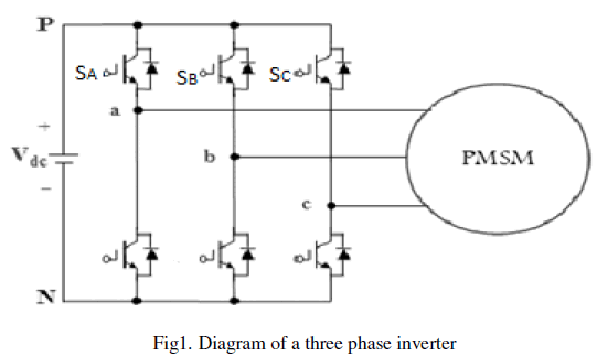
switching modes of inverter[3]. Fig.1 is the typical diagram of a three-phase voltage source inverter model. For the onoff
state of the three-phase inverter circuit, every phase can be considered as a switch S. Here, SA(t), SB(t) and SC(t) are
used as the switching functions for the three phases, respectively. |
 |
| The space vector of output voltage of inverter can be expressed as |
 |
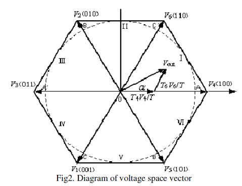
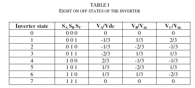
| where Vdc is the DC bus voltage of inverter and α=ej120. If we express the on state of the upper-arm with “1” and the
off state with “0”, the on-off states of three phases have eight combinations, correspondingly forming eight voltage
space vectors, as shown in Fig. 2. T refers to the operation times of two adjacent non-zero voltage space vectors in the
same zone. Both V0(000) and V7(111) are called the zero voltage space vector, and the other six vectors are called the
effective vector with a magnitude of 2Vdc/3. For example, when the output voltage vector V is within zone one, it is
composed of V4, V6, V0 and V7 and can be obtained by |
| Vout = T4V4/ T+T6V6/T |
 |
| The eight on-off states of inverter are listed in Table.I |
 |
IV. THE PROPOSED PMSM DRIVE WITH ACTIVE POWER FACTOR CORRECTION(APFC) |
 |
| Figure 3 shows the block diagram of PMSM drive with Active power Factor Correction. The APFC consists of an
energy stored element, switching device and control module. It is commonly installed between the power rectifier and
the dc link bus. The main purpose of APFC is to make the input of the power supply look like a pure resistor. In other
words, it is to make the input current waveform in phase with the input voltage waveform so that there is no phase
displacement between them. The operation of APFC is basically based on a controller that can output the signal to a
switching device to control the energy being stored or released in the reactive elements[1]. In such a way, the input
current waveform can be adjusted. The magnitude and phase of the input current waveforms by proper control can
follow that of the input voltage waveform. Consequently, the power factor improvement can be achieved and further,
the voltage stability can be obtained as well[2]. The dc link voltage for the inverter is obtained from PFC block.
The stator currents and rotor position of PMSM are given to the FOC, which controls the flux and torque components.
The current error signals are used in controllers to generate reference voltages Vα and Vβ, which are the inputs of
SVM. Space Vector modulation gives signals required for driving the inverter. By using inverter three phase supply is
given to the PMSM |
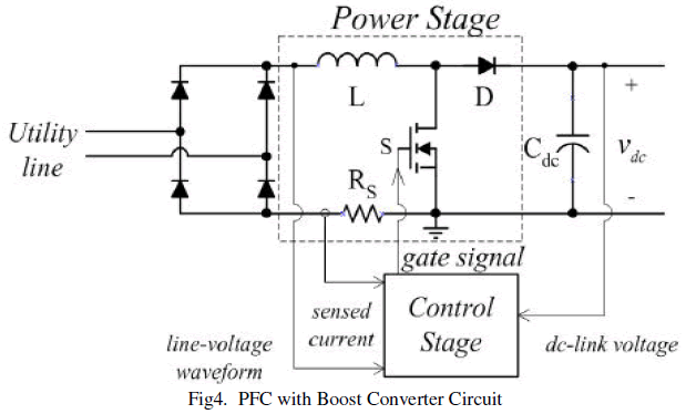 |
| Figure 4. shows the circuit of power factor correction circuit with boost converter. An uncontrolled diode rectifier with
a boost converter is used to convert the single phase AC voltage into a constant DC link voltage, which is fed to the
three phase inverter supplying a PMSM. The boost converter is the widely used topology for achieving power factor
correction[2]. This converter draws nearly unity power factor current from the AC mains and eliminates a harmonic
current which regulates the DC link voltage even under fluctuating voltage conditions of AC mains. This circuit uses a
diode bridge rectifier, an inductor which is connected in series with the supply, a switch MOSFET and an output
capacitor. The bulk energy storage capacitor sits on the output side of the converter rather than just after the diode
rectifier bridge. The average inductor current which charges the bulk capacitor is proportional to the utility line voltage.
For proper operation, the output voltage must be higher than the peak line voltage and current drawn from the line must
be proportional to the line voltage. In circuit operation, it is assumed that the inductance of boost inductor is large so
that it can be represented by constant current source and that the output ripple voltage is negligible so that the voltage
across the output filter capacitor can be represented by constant voltage source. |
V. DESIGN EQUATIONS OF BOOST POWER FACTOR CORRECTION CIRCUIT |
| The AC input voltage given to the power factor correction circuit is 100V and input frequency is 50Hz. The selection
of boost converter components is based on the following equations |
| Maximum input power |
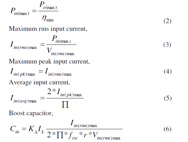 |
| KΔIL = Inductor current ripple factor (20% in this design)
r= high frequency voltage ripple factor typically from 3% to 9% ( 5% used in this design). |
| Switching frequency, fsw= 100KHz
Minimum input peak voltage, |
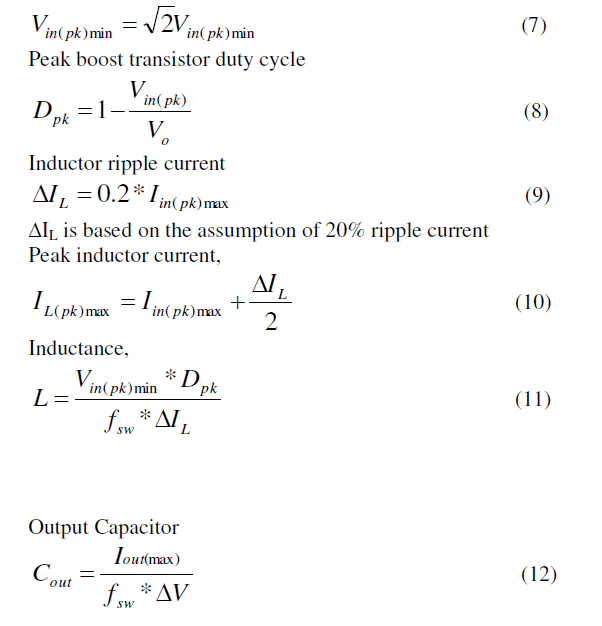 |
| where fsw is the switching frequency and ΔV is desired peak to peak output voltage ripple. |
VI. SIMULATION RESULTS |
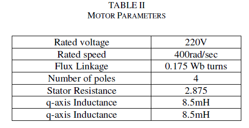
| A field oriented controlled PMSM is simulated using MATLAB / SIMULINK. Simulation of PMSM drive have been
carried out using the parameter summarized in the Table II. Table III shows the parameters of PFC boost converter.
The simulation time used is 0.5s. |
 |
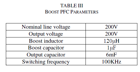 |
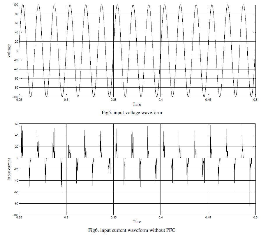
| It can be seen that a better power factor of 0.99 is achieved using the designed PFC circuit. The proposed converter
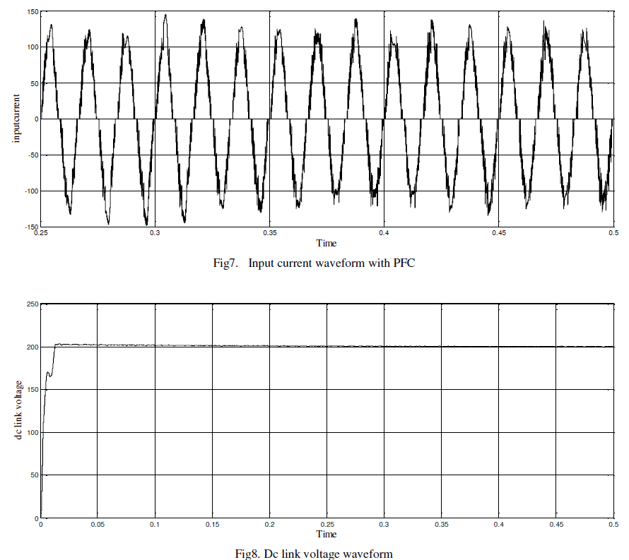
provides improved power factor and efficiency. The input voltage is shown in Fig 5. Fig 6 and 7 shows the input current
waveform without and with PFC respectively. The waveform clearly indicates that the voltage and current waveform is
in phase with each other when PFC is employed. The dc link voltage is shown in fig 8. A constant dc link voltage of
200V is obtained which is given to the three phase inverter. |
 |
 |
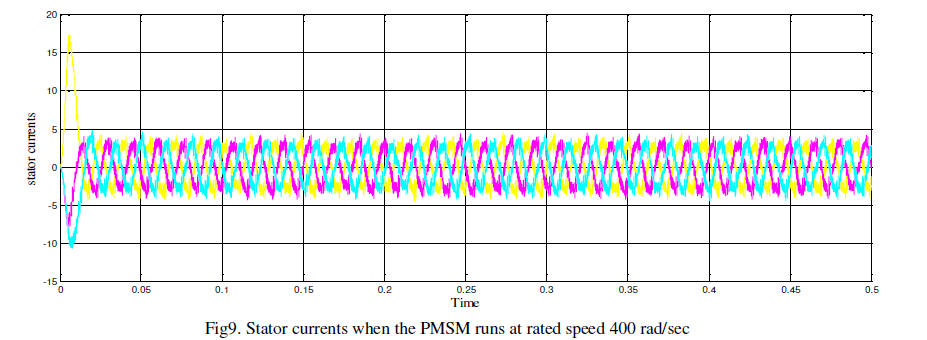
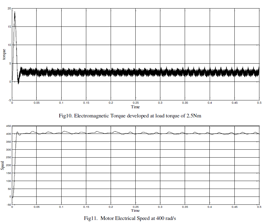
| When the parameters of speed regulator are set as Kp=10, Ki=1; the q-axis current regulator is set as Kp=1, Ki =.005;
the d-axis current regulator is set as Kp=.005, Ki =.0001, the simulated current, torque and rotor speed of the PMSM
are shown in Fig.9,10 and 11 respectively. It can be seen that the simulations agree with common operational
characteristics, proving the validity of the presented model. The simulation reference speed is set as 400 rad/s. Load
torque is given as 2.5 Nm. From the simulations, it can be seen that the startup speed of motor is fast and is able to
follow the reference speed. The parameters of PMSM used in the simulation model are listed in Table II. |
 |
 |
VII.CONCLUSION |
| This paper illustrates the simulation study of implementation of boost PFC converter with PMSM drive. With installing
the proposed active PFC controller, it can achieve smooth output dc link voltage, which is applied to the PMSM motor
drive, and obtain the sinusoidal line current waveform with lower total harmonic distortion. From the simulation study,
it is established that the PMSM with boost PFC converter provides a input power factor of 0.99. A Space Vector
Modulation-Permanent Magnet Synchronous Motor drive has been introduced here. The SVM inverter increases the
output voltage and lowers the output harmonic distortions compared with the conventional sinusoidal PWM inverter.
The field oriented control using space vector modulation allows easy implementation of the PMSM drive with less
harmonics.The advantages of the proposed drive are confirmed by the simulation results.Therefore, the power factor
and overall efficiency of the PMSM drive with APFC can be predicted to increase considerably. |
References |
- Alipio BC, David FC, Isabel RS, Juan CNM. Manuel AE. Comparison of batch, stirred flow chamber, and column experiments to study adsorption, Desorption and transport of carbofuran within two acidic soils. Chemosphere. 2012; 88(1): 106-120.
- Arnaud B, Richard C, Michel S. A comparison of five pesticides adsorption and Desorption processes in thirteen contrasting field soils. Chemosphere. 2005; 61(5): 668-676.
- Chunxian W, Jin-Jun W, Su-Zhi Z, Zhong-Ming Z. Adsorption and Desorption of Methiopyrsulfuron in Soils. Pedosphere. 2011; 21(3): 380-388.
- Chunxian W, Suzhi Z, Guo N, Zhongming Z, Jinjun W. Adsorption and Desorption of herbicide monosulfuron-ester in Chinese soils. J Environ Sci. 2011; 23(9): 1524-1532.
- Christine MFB, Josette MF. Adsorption-desorption and leaching of phenylurea herbicides on soils. Talanta. 1996; 43(10): 1793-1802.
|