ISSN ONLINE(2278-8875) PRINT (2320-3765)
ISSN ONLINE(2278-8875) PRINT (2320-3765)
K.Maniraj
|
| Related article at Pubmed, Scholar Google |
Visit for more related articles at International Journal of Advanced Research in Electrical, Electronics and Instrumentation Engineering
The main objective of the project is to enhance the power quality by using dstatcom with reduced number of sensors. The control algorithm also proposed with reduced number of current and voltage sensors. a current control technique is proposed to control the reactive power flow from a grid through a three-phase parallel-connected inverter to the load. The parallel-connected inverter ensures active and reactive power flow from the grid with lowcurrent total harmonic distortion even in the presence of nonlinear load. A p–q theory-based Hilbert transformation approach is used to find the reference current of the parallel-connected inverter to ensure desired operating conditions at the grid terminal. The proposed current controller is simple to implement and gives superior performance over the conventional current controllers, such as rotating frame proportional–integral controller or stationary frame proportional resonant controller. The stability of the proposed controller is ensured by direct Lyapunov method. Detailed experimental results are presented to show the efficacy of the proposed current control scheme along with the proposed nonlinear controller to control the reactive power flow and to eliminate the THD in the source current
Keywords |
| Dstatcom, Inverter, Lyapunov method, pq theory, THD. |
I.INTRODUCTION |
| The increased use of power electronic controlled equipment and non linear electronic devices in power system has given rise to a type of voltage and current waveform distortion called as ‘harmonics’ .The motive of electricity provider companies is to supply uninterrupted sinusoidal supply voltage and current of proper magnitude with negligible harmonic contents. The quality of the supply should be as possible as recommended by the international regulating bodies such as IEC 61000-3-2, IEEE 519-1992. However, it is always difficult to achieve the above goals due to rapidly increasingly nonlinear load. Non-linear loads, especially power electronics converters based adjustable speed drives, computer power supply, furnaces, etc. generate harmonic currents and voltages in electrical systems. These harmonics cause equipment overheating, blown capacitor fuses, distorted voltage waveform, low power factor, eddy current losses on transformer, oscillatory torque response and reduces the efficiency of the system. Excessive neutral current is also major problem in case of three-phase four-wire systems .Over- sizing, heating and losses in neutral conductors are major drawbacks of excessive neutral current. Traditionally, passive filters have used to eliminate the current harmonics and to improve the power factor. Their main advantage is high efficiency and low cost. However, they are bulky, load dependent and create resonance problems. Filtering performance is effected by the variation of source impedance and frequency. |
| Most of the more important international standards define power quality as the physical characteristics of the electrical supply provided under normal operating conditions that do not disrupt or disturb the customer’s processes. Therefore, a power quality problem exists if any voltage, current or frequency deviation results in a failure or in a bad operation of customer’s equipment. However, it is important to notice that the quality of power supply implies basically voltage quality and supply reliability. Voltage quality problems relate to any failure of equipment due to deviations of the line voltage from its nominal characteristics, and the supply reliability is characterized by its adequacy (ability to supply the load), security (ability to withstand sudden disturbances such as system faults) and availability (focusing especially on long interruptions). |
| Power quality problems are common in most of commercial, industrial and utility networks. Natural phenomena, such as lightning are the most frequent cause of power quality problems. Switching phenomena resulting in oscillatory transients in the electrical supply, for example when capacitors are switched, also contribute substantially to power quality disturbances. Also, the connection of high power non-linear loads contributes to the generation of current and voltage harmonic components. Between the different voltage disturbances that can be produced, the most significant and critical power quality problems are voltage sags due to the high economical losses that can be generated. Shortterm voltage drops (sags) can trip electrical drives or more sensitive equipment, leading to costly interruptions of production .For all these reasons, from the consumer point of view, power quality issues will become an increasingly important factor to consider in order to satisfy good productivity. On the other hand, for the electrical supply industry, the quality of power delivered will be one of the distinguishing factors for ensuring customer loyalty in this very competitive and deregulated market. To address the needs of energy consumers trying to improve productivity through the reduction of power quality related process stoppages and energy suppliers trying to maximize operating profits while keeping customers satisfied with supply quality, innovative technology provides the key to cost-effective power quality enhancements solutions. However, with the various power quality solutions available, the obvious question for a consumer or utility facing a particular power quality problem is which equipment provides the better solution. |
II. SHUNT ACTIVE FILTER |
| The power electronic converters utilize switching devices for high power efficiency. The switching action generates transient and spurious frequencies, which have intolerable effects on the power source. Electromagnetic interference radiated or conducted through the supply line also affects the load and other nearby equipment. Hence, it is necessary to filter both input and output or both. Filters for waveform improvement are classified as passive filter, active filter or a combination of both, known as hybrid filter. |
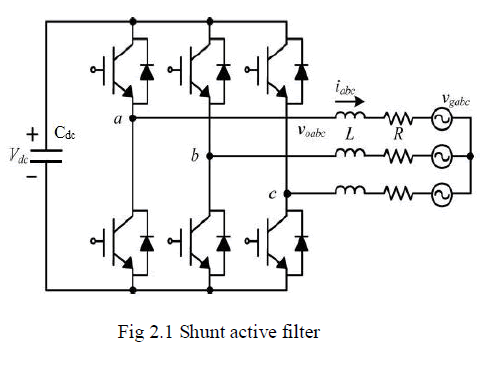 |
| R - Resistor |
| L - Inductor |
| Cdc - DC capacitor |
| Due to the intensive use of power converters and other non-linear loads in industry and by consumers in general, it can be observed an increasing deterioration of the power systems voltage and current waveforms. The presence of harmonics in the power lines results in greater power losses in distribution, interference problems in communication systems and, sometimes, in operation failures of electronic equipment, which are more and more sensitive since they include microelectronic control systems, which work with very low energy levels. |
| Because of these problems, the issue of the power quality delivered to the end consumers is, more than ever, an object of great concern. International standards concerning electrical power quality (IEEE-519, IEC 61000, EN 50160, among others) impose that electrical equipment and facilities should not produce harmonic contents greater than specified values, and also specify distortion limits to the supply voltage. Meanwhile, it is mandatory to solve the harmonic problems caused by those equipment already installed. Passive filters have been used as a solution to solve harmonic current problems, but they present several disadvantages, namely: they only filter the frequencies they were previously tuned for; their operation cannot be limited to a certain load; resonances can occur because of the interaction between the passive filters and other loads, with unpredictable results. To cope with these disadvantages, recent efforts have been concentrated in the development of active filters. |
III. REFERENCE CURRENT GENERATION |
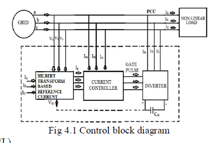
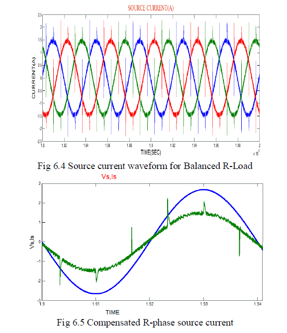
| The three phase three wire system considered in this section consists of a set of three phase non linear load. The three phase non linear load is the diode bridge rectifier with R load. The line current drawn by this non linear load contains substantial amount of harmonics. In order to reduce the current harmonics, control the reactive power flow, current unbalance the Shunt active power filter is proposed. Active compensation or APF can solve the problem of harmonic and reactive power simultaneously based on estimated reference currents signal. The pq theory based Hilbert transformation is used. |
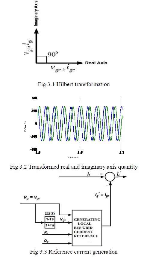 |
| The transfer function of the Hilbert transformation is |
| H(s) = (1-Ts)/ (1+Ts) |
| Where T = 1/ω and ω is the fundamental power frequency in radians per second. By using this technique, vgi is estimated from the instantaneous measurement of vgr. Therefore, in terms of time-domain convolution, |
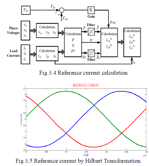
| Using p–q theory, the instantaneous active and reactive power flow balance equation at the grid can be written as follows, By inverting the matrix the igr and igi can be solved. The real grid current reference ig* can be calculated as follows |
| If Kirchhoff’s Current Law (KCL) is applied at the PCC terminal, the reference current for the CCVSI is found by measuring the load current iS , as given by |
| Here the load current and the source voltage is sensed for the reference current generation. depending upon the average load power requirements from the source the current control action has been implemented for the parallel connected inverter. |
 |
IV. LYAPUNOV CONTROLLER |
| CCVSI current reference ic* can have any type of periodic shape (i.e., sinusoidal or non sinusoidal shape), depending on the load. In order to ensure proper power flow, a fast current tracking controller is needed. The current tracking system of the CCVSI can be modeled as a first-order system. Neglecting the switching-frequency-related harmonics voltages, the VSI is modeled as a dependent voltage source vinv = Vdc × vc , where vc is the control signal of the sine PWM inverter. The dynamic equation of the CCVSI current ic can be written as follows |
 |
| dic/dt=(-R*ic/L)+(Vdc*Vc/L)-(Vg/L) |
| To analyze the system from control point of view, the state of the system is chosen as x = ic , control input u = vc , disturbance input d = −(1/L)vg , state function f(x) = −(R/L)I c , and the input function b(x) = Vdc/L. Therefore, the state equation of the system can be written as follows |
| dx/dt=f(x)+b(x)u+d |
| However, the considered model of the sine-pulse-width modulation (SPWM) inverter is simple and it does not consider any unpredictable nonlinear periodic disturbances dup (one such possible source is the blanking time in the inverter driver circuit). In actual circuit, these nonlinear periodic disturbances play important roles. In practical cases, the disturbance term d consists of not only grid voltage disturbance −(1/L)Vg , but also the unpredictable nonlinear disturbances as follows |
| d= − (Vg/L) +dup |
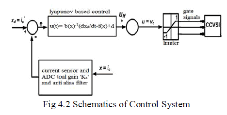 |
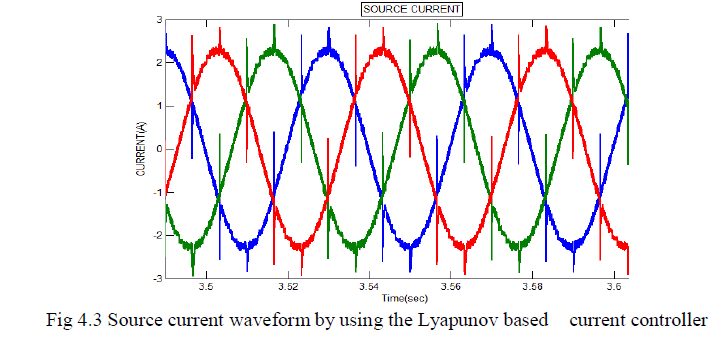
| It is needed to generate the control input u (t) so that x = ic tracks the reference value xd = ic* . The dynamic tracking error can be written as e = xd − x. It is required to find out a control input u(t) such that tracking error e(t) asymptotically converges to zero. Lyapunov direct method is used to find out the control input u(t) for the specific application. |
| The Lyapunov function is taken as follows |
| V=1*e2/2 |
 |
 |
V. CONTROL OF DC CAPACITOR |
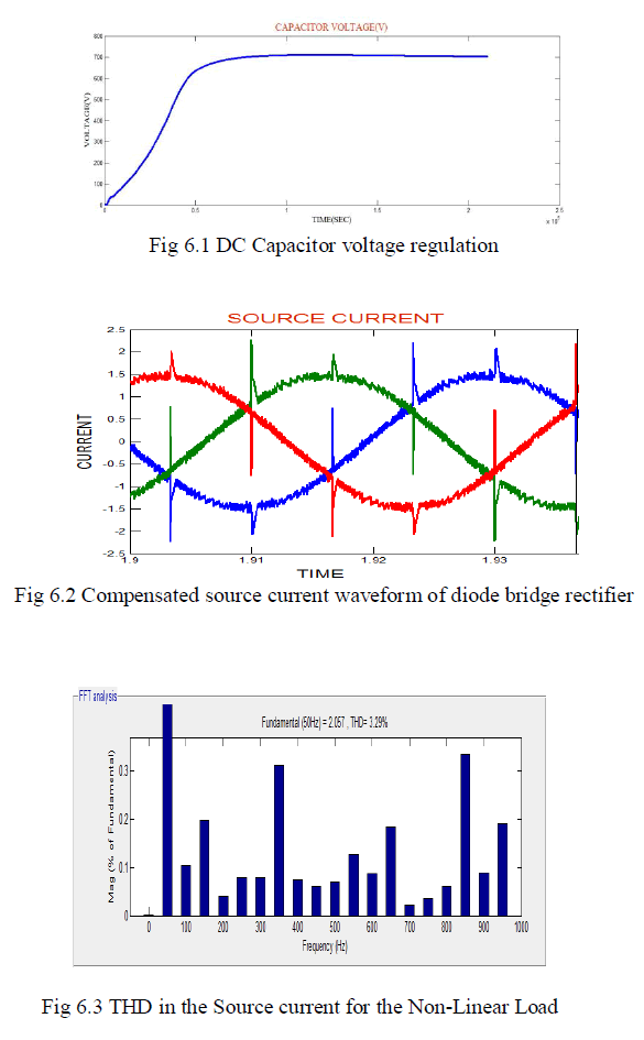
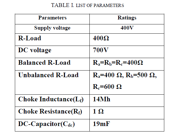
| DSTATCOM is supplied through a dc capacitor. The dc voltage stored (Vdc) in the storage capacitor Cdc must be maintained in order for perfect current tracking. This however will not be possible unless the loss due to Rf is somehow replenished by drawing additional power from the source. In order to accommodate this, the real power supplied by the source is not equal to the average load power |
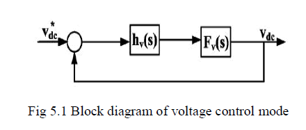 |
| Transfer function of the converter is, |
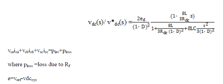 |
| For the Inverter, very high value of Rdc has been taken |
| Input current regulation in the inverter is achieved by adjusting the duty cycle. Generally three basic algorithm used are P, PI and PID. Here in this project PI controller used. The PI consists of two basic modes that are proportional modes and integral modes. A proportional controller (kp) reduced settling time and reduced the error but not eliminated it. An integral controller (ki) will have the effect of eliminating the steady-state error. Limiter is used to control the duty cycle within the desirable band |
 |
 |
 |
 |
VII. CONCLUSION |
| The grid interfacing inverter for three phase three wire system is simulated using MATLAB/SIMULINK. The closed loop response of three leg VSI type shunt active filter is found. The reference currents are generated by using pq theory based Hilbert transformation technique. The Total harmonic distortion in the source current is reduced. It compensates the reactive power flow between the source and the load, source current shaping, current unbalance and it maintains the power factor near to unity. |
References |
|