Keywords
|
| Direct torque control (DTC), induction motor, Power Quality, Voltage Source Converter (VSC), Statcom, THD |
INTRODUCTION
|
| The DTC based induction motor drive (IMD) uses a single-phase or three-phase uncontrolled ac-dc converter (for rectification of ac mains voltage), an energy storage element (capacitor filter for smoothening the dc link voltage), and a three-phase voltage source inverter (VSI) for feeding a three-phase squirrel cage induction motor. Such type of utility interface suffers from problems related to power quality such as poor power factor, injection of current harmonics into the ac mains, variation in dc link voltage with fluctuations in the voltage of input ac supply, equipment overheating due to harmonic current absorption, voltage distortion at the point of common coupling (PCC) due to the voltage drop caused by harmonics currents flowing through system impedance and decreased rectifier efficiency. These power quality problemscan cause malfunction of sensitive electronic equipments, interference in telephone and communication lines due to highfrequency switching, failure of switching capacitors and other power equipment and loss of data. |
| Early STATCOM generally used the zigzag transformer in the main circuit topology as voltage source inverter. However, the zigzag transformer has some difficulties, which is hard to overcome in terms of cost, transformer loss as well as the control. When the inverter is used as the main circuit topology, STATCOM has a little floor space, easy to split-phase control, high reliability, and easy expansion of capacity, etc. In addition, because it has no use for the zigzag transformer, it makes the existing STATCOM free of the most serious problems such as device over-voltage caused by the magnetic saturation and nonlinearity in the transformer excitation circuit .So the inverter structure for large capacity STATCOM is concerned by a large number of engineering designers more and more. |
DTC BASED INDUCTION MOTOR DRIVE
|
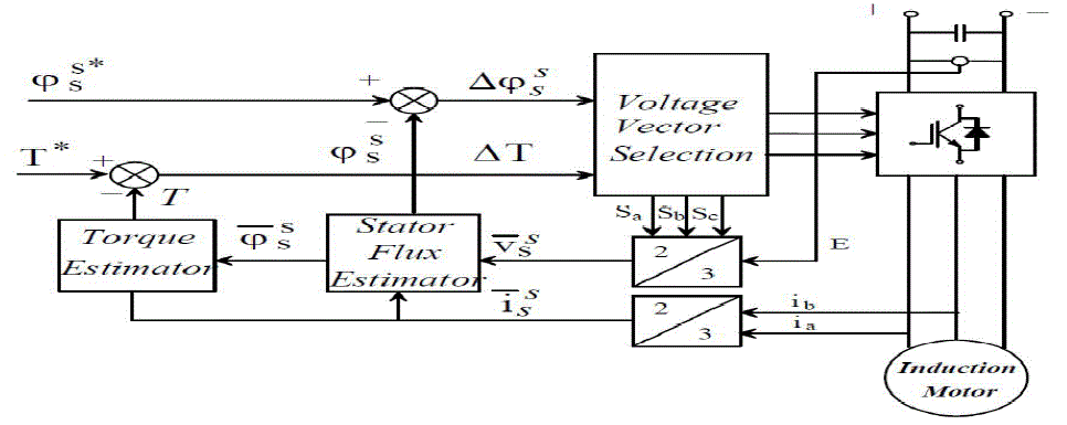
| In principle the DTC method selects one of the six nonzero and two zero voltage vectors of the inverter on the basis of the instantaneous errors in torque and stator flux magnitude. |
 |
| Assuming the voltage drop Rsiss small, the stator flux is driven in the direction of the stator voltage v ss |
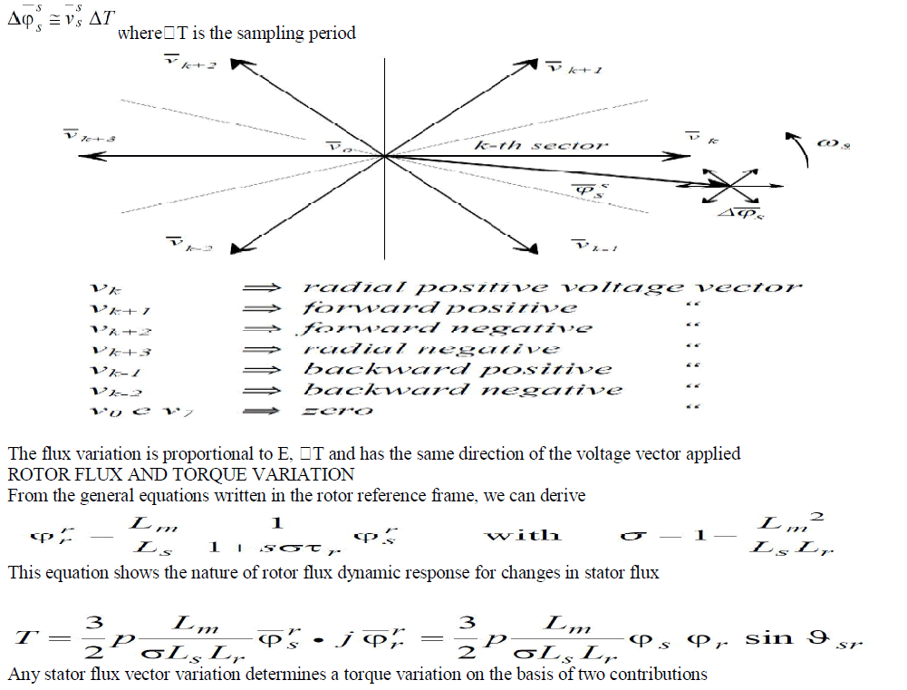 |
| I) The variation of the stator flux magnitude |
| II) The variation of the stator flux phase angle with respect to rotor flux |
| Any command which causes the flux angle to change will determine a quick torque variation. |
WORKING OF STATCOM
|
 |
| In the case of two AC sources, which have the same frequency and are connected through a series reactance, the power flows will be: |
| Active or Real Power flows from the leading source to the lagging source. |
| Reactive Power flows from the higher to the lower voltage magnitude source. |
| Consequently, the phase angle difference between the sources decides the active power flow, while the voltage magnitude difference between the sources determines the reactive power flow. Based on this principle, a STATCOM can be used to regulate the reactive power flow by changing the output voltage of the voltage-source converter with respect to the system voltage |
| Modes of Operation |
| The STATCOM can be operated in two different modes: |
| A. Voltage Regulation |
| The static synchronous compensator regulates voltage at its connection point by controlling the amount of reactive power that is absorbed from or injected into the power system through a voltage-source converter. |
| In steady-state operation, the voltage V2 generated by the VSC through the DC capacitor is in phase with the system voltage V1 (δ=0), so that only reactive power (Q) is flowing (P=0). |
| 1. When system voltage is high, the STATCOM will absorb reactive power (inductive behavior) |
| 2. When system voltage is low, the STATCOM will generate and inject reactive power into the system (capacitive). Subsequently, the amount of reactive power flow is given by the equation: |
| Q = [V1(V1-V2)] / X |
| B. Var Control |
| In this mode, the STATCOM reactive power output is kept constant independent of other system parameter. |
SIMULATION
|
| With the help of the MATLAB Simulink model of three phase induction motor and STATCOM is easily established .The following figure ( shows the various parts of the motor model with |
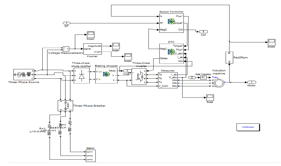 |
| The speed controller is based on a PI regulator, shown below. The output of this regulator is a torque set point applied to the DTC controller block.The Torque & Flux calculator block is used to estimate the motor flux αβ components and the electromagnetic torque. This calculator is based on motor equation synthesis.The αβ vector block is used to find the sector of the αβ plane in which the flux vector lies. The αβ plane is divided into six different sectors spaced by 60 degrees.The Flux & Torque Hysteresis blocks contain a two-level hysteresis comparator for flux control and a three level hysteresis comparator for the torque control. The description of the hysteresis comparators is available below.The Switching table block contains two lookup tables that select a specific voltage vector in accordance with the output of the Flux & Torque Hysteresis comparators. This block also produces the initial flux in the machine.The Switching control block is used to limit the inverter commutation frequency to a maximum value specifiedby the user. |
RESULTS AND DISCUSSIONS
|
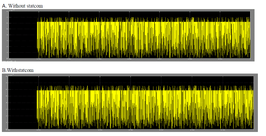
| Performance of the DTC based IMD is studied for both the configurations namely, with and withoutSTATCOM at the front end. Waveforms consist of Fourier and FFT of source phase voltage (vas)rotor speed (Nr), electromagnetic torque (Te) for the rating of 5 HP, 460V, 60Hz, 1750rpm The ac mains voltage waveform and its harmonic spectra at load is shown in which show that THD at no load. From these results it can be concluded that it is necessary to use improved power quality converters at front end of the DTC based IMD. As the next step, a STATCOM is employed in the waveforms of a DTC based IMD for load conditions fed from a STATCOM at the front end are shown in The ac mains current and its harmonic spectra for load.Fourier response with response show ripple within .09% and .07% with stacom. It can be noted that the THD of ac mains voltage at load is 0.01%. A significant improvement as compared to the case without statcom where THD is 24.9%.Fourier response with and without statcom are shown |
 |
| C.FFT (WITHOUT STACOM) THD=24.9% |
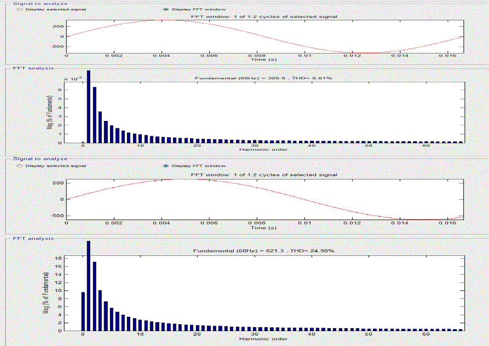 |
| D.FFT(WITH STATCOM) THD=0.01% |
References
|
- Bose, B. K.; "Power Electronics and AC Drives". Prentice-Hall. 1986.
- Mohan, Undeland, Robbins. “Power Electronics".Wiley.Second edition. 1989.
- Novotny, D. W. and Lipo, T. A. “Vector Control and Dynamics of AC Drives.” Oxford University Press Inc, New York, 1996.
- Vas, P. " Sensor less Vector and Direct Torque Control". Oxford University Press 1998.
- Paul C. Krause, Oleg Wasynczuk, Scott D. Sudhoff “Analysis Of Electric Machinery And Drives” Second Edition, IEEE Press WileyInterscience 2002.
- Chintan Patel, Student Member, IEEE, Rajeevan P. P., AnubrataDey, RijilRamchand, Student Member, IEEE, K. Gopakumar, SeniorMember, IEEE,and Marian P. Kazmierkowski, Fellow, IEEEâÃâ¬Ãâ¢Fast Direct Torque Control of an Open-End Induction Motor Drive Using 12-SidedPolygonal Voltage Space Vectors’’ IEEE TRANSACTIONS ON POWER ELECTRONICS, VOL. 27, NO. 1, JANUARY 2012.
- Tejavathu Ramesh, Anup Kumar Pandl, Member IEEE, Y Suresh and Suresh Mikkili Department of Electrical Engineering, NationalInstitute of Technology, Rourkela, Orissa, India âÃâ¬Ãâ¢Direct Flux and Torque Control of Induction Motor Drive for Speed Regulator using PI and FuzzyLogic Controllers,’’ IEEE- International Conference On Advances In Engineering, Science And Management (ICAESM -2012) March 30, 31, 2012
- Zhao Liu, Bangyin Liu, Member, IEEE, ShanxuDuan, and Yong KangâÃâ¬Ãâ¢A Novel DC Capacitor Voltage Balance Control Method for CascadeMultilevel STATCOM,’’IEEE Transactions On Power Electronics, VOL. 27, NO. 1, JANUARY 2012
|