Keywords
|
| Direct torque control (DTC), induction motor, Power Quality, Voltage Source Converter (VSC), STATCOM, GTO, SHEM, Multilevel Inverter, THD. |
INTRODUCTION
|
| Induction motors, the most widely used motors in industry, have been traditionally operated in open loop control applications, for reasons of cost, size, reliability, ruggedness, simplicity, efficiency, less maintenance, ease of manufacture and their capability to operate in dirty or explosive conditions. |
| However, because the induction motor requires more complex control methods, the dc motor has dominated in high performance adjustable speed drive applications. With developments in micro processors/digital signal processor (DSP), power electronics and control theory, the induction motor can now be used in high performance variable-speed and cost-sensitive applications, such as heating, ventilation, and air conditioning (HVAC) systems, waste water treatment plants, blowers, fans, textile mills, rolling mills etc. due to their advantages like energy conservation and reduction in inrush current drawn, etc. The use of variable frequency induction motor drives (VFIMDs) has further increased due to their capability to achieve good dynamic performance using vector control (or field oriented control-FOC) and direct torque and flux control (DTC). With these control techniques, induction motor drives can achieve similar or even better performance than dc motor drives. It is well known that the FOC needs complicated co-ordinate transformations to decouple the interaction between the flux and torque components of stator currents. The implementation of FOC is difficult and very sensitive to parameter variations. Direct torque control (DTC) [2] is relatively simple in implementation and less sensitive to the parameter variations yet performs as well as FOC technique [1], [3]. It is based on the decoupled and independent control of stator flux and torque providing a quick and robust response. However, the conventional DTC strategy using switching table of a six pulse voltage source inverter (VSI) presents notable torque, flux, current and speed ripple. In DTC, stator voltage vectors are selected according to the differences between the reference and actual torque and stator flux linkage. |
| The DTC based induction motor drive (IMD) [8] uses a single-phase or three-phase uncontrolled ac-dc converter (for rectification of ac mains voltage), an energy storage element (capacitor filter for smoothening the dc link voltage), and a three-phase voltage source inverter (VSI) for feeding a three-phase squirrel cage induction motor. Such type of utility interface suffers from problems related to power quality such as poor power factor, injection of current harmonics into the ac mains, variation in dc link voltage with fluctuations in the voltage of input ac supply, equipment overheating due to harmonic current absorption, voltage distortion at the point of common coupling (PCC) due to the voltage drop caused by harmonics currents flowing through system impedance and decreased rectifier efficiency. These power quality problems can cause malfunction of sensitive electronic equipments, interference in telephone and communication lines due to high frequency switching, failure of switching capacitors and other power equipment and loss of data. Different international organizations have given guidelines to impose strict limits on the levels of harmonic current emissions. |
| Different active and passive filtering techniques [4] are used to mitigate distortions in the input line current. The approach of active power factor correction can achieve unity power factor and very low total harmonic distortion (THD) of ac mains current along with a good regulation of the dc link voltage. But the disadvantages are high cost (cost is nearly doubled), increased complexity in control (particularly if optimum performance is desired under preexisting supply voltage distortions), and higher dc-link voltage due to boost operation. |
| Early STATCOM generally used the zigzag transformer in the main circuit topology as voltage source inverter. However, the zigzag transformer has some difficulties, which is hard to overcome in terms of cost, transformer loss as well as the control. When the cascaded multilevel inverter is used as the main circuit topology, STATCOM has a little floor space, easy to split-phase control, high reliability, and easy expansion of capacity, etc. In addition, because it has no use for the zigzag transformer, it makes the existing STATCOM free of the most serious problems such as device over-voltage caused by the magnetic saturation and nonlinearity in the transformer excitation circuit .So the cascaded multilevel inverter structure for large capacity STATCOM is concerned by a large number of engineering designers more and more. |
DTC BASED INDUCTION MOTOR DRIVE
|
| DTC uses a simple switching table to determine the most Opportune inverter state to attain a desired output torque. By means of current and voltage measurements, it is possible to compute approximately the instantaneous stator flux and output motor torque. The control algorithm based on flux and torque hysteresis controllers determines the voltage required to drive the flux and torque to the desired values within a fixed time period. The fundamental functional blocks used to implement the DTC scheme are represented [5] in Fig. 1. |
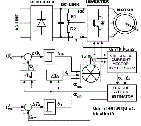 |
| Fig. 1. DTC Induction Motor scheme |
| The stator flux vector - and the torque produced by the motor, Gem, can be estimated respectively. These equations only require the knowledge of the previously applied voltage vector Vs, measured stator current Is, stator resistance Rs, and the motor poles number p. |
 |
 |
| Once the electromagnetic torque and stator flux magnitude are estimated, a hysteresis control is done and the voltage vectors to be applied are obtained from a switching table. The stator voltage polar components (Vsa,Vsß) on perpendicular (a,ß) reference frame result from measured dc-link voltage [5] Udc and the switching controls logical states Sa, Sb, and Sc is given as |
 |
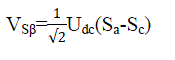 |
| and stator current components (Ia,Iß) |
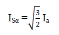 |
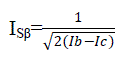 |
| The stator resistance can be assumed constant. During a switching period, the voltage vector applied to the motor is constant. By integrating the back electromotive force (EMF), the stator flux can be estimated using equation no.(5) |
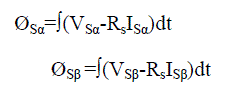 |
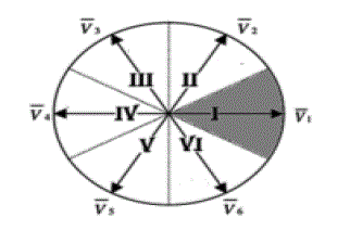 |
| Fig. 2. DTC sectors and inverter voltage vectors |
| During the switching period, each voltage vector is constant and (5) is then rewritten as |
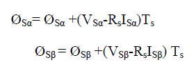 |
| Where Ts is the control loop period. |
| The magnitude of the stator flux can be estimated by |
 |
| We can find the flux vector zone using the stator flux components (fsa,fsß). By using the flux components, current components and IM number of poles, the electromagnetic torque can be calculated by |
 |
| As shown in Fig.2, six equally spaced voltage vectors having the same amplitude and two zero-voltage vectors are the only switching combinations, which can be chosen for an inverter operation. The selection of a voltage vector is made to preserve the torque and the stator flux inside the hysteresis bands limits. |
WORKING OF STATCOM
|
| STATCOM is a primary shunt device of the FACTS family, which uses power electronics to control power flow and improve transient stability on power grids. The STATCOM regulates voltage at its terminals by controlling the amount of reactive power injected into or absorbed from the power system. For purely reactive power flow the three phase voltages of the STATCOM must be maintained in phase with the system voltages. The variation of reactive power is performed by means of a VSC connected through a coupling transformer. The VSC uses forced commutated power electronics devices (GTO's or IGBT's) to synthesize the voltage from a dc voltage source. The operating principle of STATACOM is explained in Fig.4. It can be seen that if V 2> V I then the reactive current Iq flows from the converter to the ac system through the coupling transformer by injecting reactive power to the ac system. On the other hand, if V 2< V I then current Iq flows from ac system to the converter by absorbing reactive power from the system. Finally, if V2= VI then there is no exchange of reactive power. The amount of reactive power exchange is given by: |
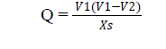 |
| V I: Magnitude of system Voltage. |
| V 2: Magnitude of STATCOM output voltage. |
| Xs: Equivalent impedance between STATCOM and the system. |
 |
| Fig. 3: Schematic Configuration of STATCOM |
CASCADED MULTILEVEL CIRCUIT
|
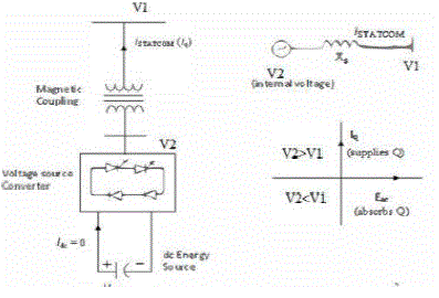
| A cascaded multi-level converter circuit is shown in Fig. 5. It is a three phase VSC which comprises of three single phases and each phase consists of H-bridges connected in series. The three phases in the converter are star connected. Each single phase H-bridge converter has two arms consisting of two pairs of GTO and diode connected in anti-parallel. Each H-bridge has its own capacitor, acting as a voltage source. Individual capacitors of same capacitance are selected to meet the economic and harmonic criteria [7]. |
| The peak output voltage of STATCOM is N times to that of the capacitor voltage, where N is the number of Hbridges in each phase. Each H-bridge generates three voltage levels +Vdc, 0 and - Vdc and the total output voltage of each phase is the combination of individual H-bridge voltages. A STATCOM with N converters per phase can synthesize 2N+1 voltage levels. |
 |
| Fig. 4 Single phase 9 level H-bridge inverter and switching strategies |
| The output voltage waveform of the cascaded N-Level STATCOM depends on the switching pattern, which is controlled by the switching angles of the converters. These switching angles can be independently selected, but appropriate switching angles are required to achieve goodnquality of the output voltage waveform. Lower order harmonics can be eliminated in the output waveform. The amplitude of the odd harmonic order of the output voltage with 2N+1 level can be represented using Fourier's series method as, |
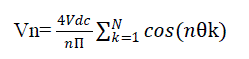 |
| Where, |
| Vn is the amplitude of voltage harmonic of nth order |
| V de is the DC voltage across the capacitor |
| N is the number of the bridges in each phase |
| n is the odd harmonic order In this paper a nine level cascaded multilevel converter is designed and is simulated in MATLAB simulink environment. |
SIMULATION RESULTS
|
| In This paper, The proposed model of multilevel STATCOM connected in shunt configuration to a three phase source feeding dynamic motor loads is developed using Simulink of MATLAB software. Simulated results demonstrate that multi level STATCOM can be considered as a variable solution for solving such voltage dip problems. This thesis work aims at developing a multilevel STATCOM for induction machines with voltage dip. |
| Direct torque control (DTC) is a well-known control scheme of induction motor (IM) drives that provides fast and robust control of the IM. DTC has attached considerable attention as a result of its use as the main platform for ABB inverter technology. The DTC has been implemented using either variable switching frequency or constant sampling techniques. |
| This paper deals with the design and implementation of a multilevel voltage source converter based static synchronous compensator (STATCOM) employing an effective modulation based on three-phase induction motor (IM) under direct torque control (DTC) technique in a MATLAB/Simulink. So large starting currents and objectionable voltage drop during the starting of an induction motor could be critical for the entire system. Circuit diagram as shown in fig 6. |
| This large voltage dip is encountered at the starting of induction motor However, the voltage dip is now within limits as the motor is already started and is drawing normal full rated current, shows the stator current, rotor current, load voltage, speed, electromagnetic torque with respect to time. The advantages of CHB inverter are low harmonic distortion, reduced number of switches and suppression of switching losses. The multi level STATCOM helps to improve the power factor and eliminate the Total Harmonics Distortion (THD). |
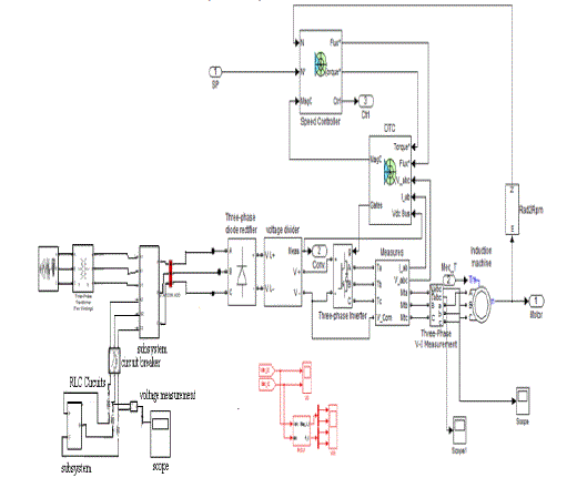 |
| Fig. 5 MATLAB Simulink model of DTC based IMD with Multi level STATCOM |
RESULTS AND DISCUSSIONS
|
| Performance of the DTC based IMD is studied for both the configurations namely, a six-pulse diode bridge rectifier and multi level STATCOM at the front end. Fig. 6 shows the dynamic performance of the drive fed from a sixpulse diode bridge rectifier for load conditions. Waveforms consist of source phase voltage (vas), source line current (ias), rotor speed (Nr), electromagnetic torque (Te) for the rating of. Pn =1.1 kW, Un =415 V, f=50 Hz, Ωn =1415 r/min, Rs =6.03 Ω, Rr = 6.085Ω, Lls = 29.9 mH, Llr = 29.9 mH, Lm =489.3 mH, J = 0.011787 Kg.m2 |
| The ac mains current waveform and its harmonic spectra at load is shown in Figs. 7 and 8 which show that THD at full load. From these results it can be concluded that it is necessary to use improved power quality converters at front end of the DTC based IMD. As the next step, a Multi level STATCOM is employed in place of the uncontrolled 6-pulse converter. The waveforms of a DTC based IMD for load conditions fed from a Multi level STATCOM at the front end are shown in Fig. 9. The ac mains current and its harmonic spectra for load as shown in Figs.10. It can be noted that the THD of ac mains current at load is 4.60%. A significant improvement as compared to the case fed from a simple diode bridge rectifier. The comparison of THD with load for DTC based |
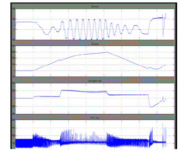 |
| Fig. 6. Dynamics of a DTC based IMD with a simple diode bridge rectifier |
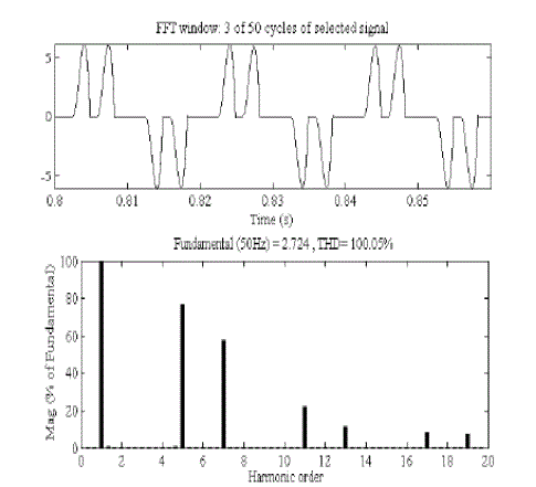 |
| Fig. 7 AC mains current waveform and harmonic spectrum for DTC based IMD with a simple diode bridge rectifier at rated load |
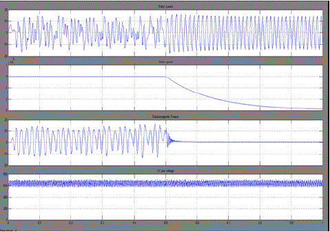 |
| Fig. 8 Dynamics of a DTC based IMD with a simple diode bridge rectifier and Multi-Level STATCOM at the front end |
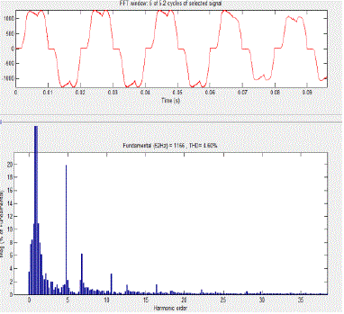 |
| Fig. 9 AC mains current and harmonic spectrum for DTC based IMD with Multi Level STATCOM at the front of DTC |
CONCLUSION
|
| Designing and implementation of a multilevel voltage source converter based static synchronous compensator (STATCOM) employing an effective modulation based on three-phase induction motor (IM) under direct torque control (DTC) technique in a MATLAB /Simulink. So large starting currents and objectionable voltage drop during the starting of an induction motor could be critical for the entire system. Thus STATCOM is an effective solution for power systems facing such power quality problems. This report deals with one of the potential applications of static compensator (STATCOM) to industrial systems for mitigation of voltage dip problem. The dip in voltage is generally encountered during the starting of an induction motor. |
| The model of multilevel STATCOM connected in shunt configuration to a three phase source feeding dynamic motor loads is developed using Simulink of MATLAB software. Simulated results demonstrate that multilevel STATCOM can be considered as a viable solution for solving such voltage dip problems. This thesis work aims at developing a multi level STATCOM for induction machines with reduced voltage dip. The advantages of CHB inverter are low harmonic distortion, reduced number of switches and suppression of switching losses. The multi level STATCOM helps to improve the power factor and eliminate the Total Harmonics Distortion (THD). |
References
|
- Bhim Singh, Pradeep Jain, A. P. Mittal and J. R. P. Gupta, âÃâ¬Ãâ¢Direct torque control: a practical approach to electric vehicle,âÃâ¬Ãâ in Proc. of IEEE PowerIndia Conference, June 2006.
- I. Takahashi and T. Noguchi, âÃâ¬Ãâ¢A new quick-response and high-efficiency control strategy of an induction motor,âÃâ¬Ãâ IEEE Trans. Ind. Appl., vol. IA- 22,no. 5, pp. 820–827, Sep./Oct. 1986.
- S. A. Zaid, O. A. Mahgoub, and K. El-Metwally, âÃâ¬Ãâ¢Implementation of a new fast direct torque control algorithm for induction motor drives,âÃâ¬ÃâIETElectr. Power Appl., vol. 4, no. 5, pp. 305–313, May 2010.
- B. Singh, B. N. Singh, A. Chandra, K. Al-Haddad, A. Pandey and D. P.Kothari, âÃâ¬Ãâ¢A review of three-phase improved power quality AC-DCconverters,âÃâ¬ÃâIEEE Trans. Industrial Electronics, vol.51, no.3, June 2004.
- BrahimMetidji, Student Member, IEEE, Nabil Taib, LotfiBaghli, Member, IEEE, ToufikRekioua,and SeddikBacha, Member, IEEE âÃâ¬Ãâ¢Low-Cost Direct Torque Control Algorithm for Induction Motor Without AC Phase Current Sensors,’’IEEETRANSACTIONS ON POWER ELECTRONICS, VOL. 27, NO. 9, SEPTEMBER 2012
- Prof. B.S.KrishnaVarma, G.Vineesha, J.Truptikumar, K.Sasank, P. Naga Yasasvi and Associate Professor of EEE âÃâ¬Ãâ¢Simulated Control System Designof a Multilevel STATCOM for Reactive Power Compensation’’ IEEE-international Conference On Advances In Engineering, Science And Management(ICAESM -2012) March 30, 31, 2012.
- Zhao Liu, Bangyin Liu, Member, IEEE, ShanxuDuan, and Yong KangâÃâ¬Ãâ¢A Novel DC Capacitor Voltage Balance Control Method for CascadeMultilevel STATCOM,’’IEEE Transactions On Power Electronics, VOL. 27, NO. 1, JANUARY 2012
- Chintan Patel, Student Member, IEEE, Rajeevan P. P., AnubrataDey, RijilRamchand, Student Member, IEEE, K. Gopakumar, Senior Member, IEEE,and Marian P. Kazmierkowski, Fellow, IEEEâÃâ¬Ãâ¢Fast Direct Torque Control of an Open-End Induction Motor Drive Using 12-Sided Polygonal Voltage Space Vectors’’ IEEE TRANSACTIONS ONPOWER ELECTRONICS, VOL. 27, NO. 1, JANUARY 2012.
- Tejavathu Ramesh, Anup Kumar Pandl, Member IEEE, Y Suresh and Suresh Mikkili Department of Electrical Engineering, National Institute ofTechnology, Rourkela, Orissa, India âÃâ¬Ãâ¢Direct Flux and Torque Control of Induction Motor Drive for Speed Regulator using PI and Fuzzy LogicControllers,’’ IEEE- International Conference On Advances In Engineering, Science AndManagement (ICAESM -2012) March 30, 31, 2012.
|