Keywords
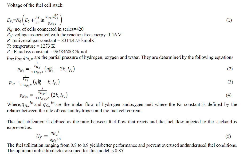
|
| Grid interfacing inverter, Pulse Width Modulation(PWM), Power Quality(PQ), Renewable Energy Sources (RES). |
INTRODUCTION
|
| The energy demand is increasing day by day which can create problems for electric utilities and end users of electric power. Renewable energy resources such as solar photovoltaic, wind, fuel cell etc. are largely integrated into the power system. The integration of Renewable Energy Resources at the distribution level is termed as Distributed Generation (DG). Distributed generation (DG) systems are presented as an alternative form to offer reliable electrical power supply. The concept is particularly interesting when different kinds of energy resources are available, such as photovoltaic panels, fuel cells or wind turbines. The utility is concerned due to the high penetration level of intermittent RES in distribution systems as it may pose a threat to network in terms of stability, voltage regulation and Power Quality (PQ).Renewable Energy Sources need power electronic interfaces for its connection to the ac grids. This way, inverters or dc-to-ac converters are connected to a common ac bus with the aim to share properly the disperse loads connected to the local grid. DG systems are required to comply with strict technical and regulatory frameworks to ensure safe, reliable and efficient operation of the overall network. With the advancement in power electronics and digital control technology, the DG systems can now be actively controlled to enhance the system operation with improved PQ at the Point of Common Coupling(PCC). However, the extensive use of power electronics based equipment and non-linear loads at PCC generate harmonic currents, which may deteriorate the quality of power. |
| A. Power Quality and Renewable Energy Resources |
| The renewable sources interconnected with the main supply can influence the power quality at the Point of Common Coupling and can pollute the electrical network with harmonic components that must not exceed the stipulated limits.Power Quality is a summarizing concept, including different criteria to judge the technical quality of an electric power delivery.The quality of power exchanged at the Point of Common Coupling (PCC) is termed as power quality. It also depends on the quality of voltage and current.Power Quality issues are any power related problem manifested in voltage, current or frequency deviation, which results in the failure or malfunctioning of operation of consumer equipment or affecting the end users. Some of the power quality issues are: |
| Harmonics |
| Loads equipped with electronic devices that absorb high frequency current components produces harmonics in grid current. Voltage harmonics are produced due to converters and by the switching of electronic components. |
| Reactive Power Burden |
| Reactive power is required to maintain the voltage to deliver active power through transmission lines. It is significant with electrical loads having coils or capacitors. Reactive power deficiency causes the voltage to sag down. Reactive power has to be balanced in grid to avoid voltage problem and to secure stable operation. |
| Over voltage and voltage dips |
| Over voltages mainly occur due to environmental phenomena such as lightning on grid. These are rare events and can be reduced using grid components. Fast reclosing action of switches in order to eliminate transient faults may cause voltage dips. |
| This paper presents an interfacing inverter for a grid connected renewable energy system. This grid interfacing inverter can be utilized for transfer of active power generated from renewable resources and reactive power compensation at the Point of Common Coupling. |
SYSTEM CONFIGURATION
|
| The system consists of RES connected to the dc-link of a grid-interfacing inverter as shown in Fig. 1. The Voltage Source Inverter is a key element of a DG system as it interfaces the Renewable Energy Source to the grid and delivers the generated power. The RES may be a DC source or an AC source with rectifier coupled to dc-link. Usually, the fuel cell and photovoltaic energy sources generate power at variable low dc voltage, while the variable speed wind turbines generate power at variable ac voltage. Thus, the power generated from these renewable sources needs power conditioning (i.e., dc/dc or ac/dc) before connecting on dc-link. The dc-capacitor decouples the RES from grid and also allows independent control of converters on either side of dc-link. Renewable Energy Source(RES) used here is fuel cell. |
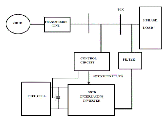 |
| Fig.1: Basic system configuration |
| A. Modelling of Fuel Cell |
| Solid Oxide Fuel Cell(SOFC) is used.SOFC is one of the most developed fuel cells showing great promise in stationary power generation applications. Some advantages of the SOFC are as follows: |
| • SOFC technology is most suited to applications in the distributed generation (ie,stationary power) market because its high conversion efficiency provides the greatestbenefit when fuel costs are higher, due to long fuel delivery systems to customer premises. |
| • SOFCs have a modular and solid state construction and do not present any movingparts, thereby are quiet enough to be installed indoors. |
| • SOFCs have extremely low emissions by eliminating the danger of carbon monoxidein exhaust gases, as any CO produced is converted to CO2 at the highoperating temperature. |
| The following assumptions are made in developing the mathematical model of the fuel cell stack. The gases considered are ideal, that is, their chemical and physical properties are not co-related to the pressure. Nernst equation is applicable and fuel cell temperature is constant at all times. The ideal gas law is used to calculate the partial pressure of all the gases. |
 |
| B. Inverter Control |
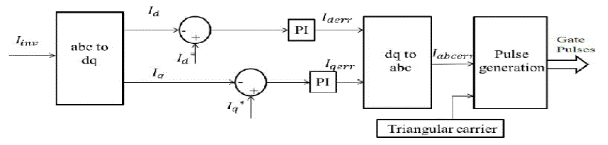 |
| Fig.2 Control technique using dq reference template with Pref , Qref inputs and triangular carrier PWM |
| Control technique used is triangular carrier Pulse Width Modulation (PWM) with dqreference template generation. The actual inverter current is sensed and it is transformed into dq co-ordinates. It is compared with the reference current values (Id* andIq* ). The error values of current is transformed back to abc co-ordinates and given to the gate pulse generation block. Reference values of active and reactive power are given as input. Reference values of d and q components of current are calculated using the following equations. |
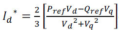 |
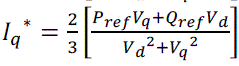 |
SIMULATIONS AND RESULTS
|
| Fuel cell is connected to the Point of Common Coupling through the grid interfacing inverter. Pulse Width Modulation is used to generate gate pulse for inverter.Fig.3 shows the Simulink model of the grid connected system |
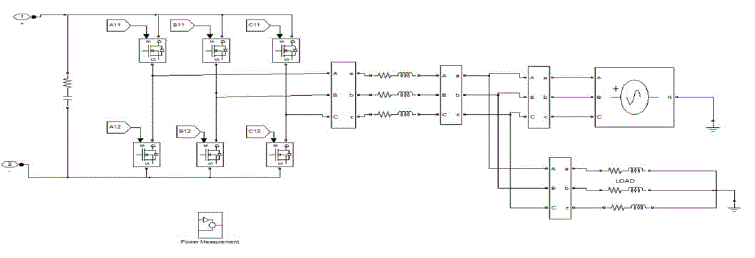 |
| Fig.3 Simulink model of the grid connected system |
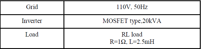
| A 12kW Solid Oxide Fuel Cell (SOFC) is connected to the grid interfacing inverter through a dc link capacitor. Two fuel cell stack of each having 420 cells are connected in parallel. Fig.4 shows the Simulink model of two fuel cell stack connected in parallel. System parameters used for simulation is shown in table 1.Simulation interval considered is from 0 to 0.5 s. |
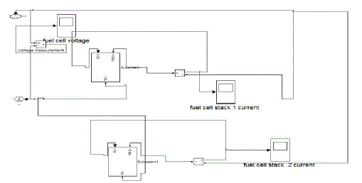 |
| Fig.4 Simulink model of fuel cell connected in parallel |
 |
 |
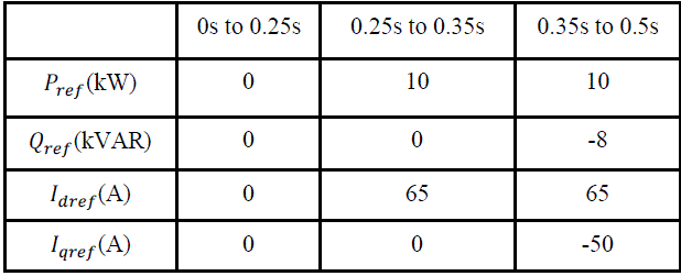
| Table 1: System Parameters |
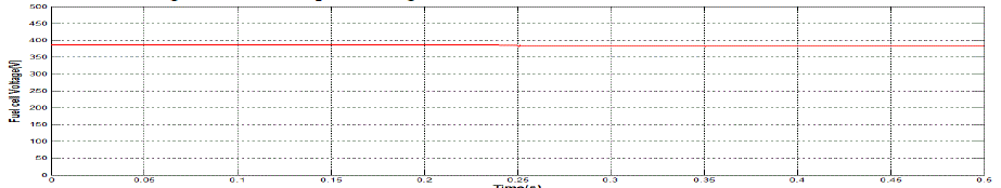
| Table 2 shows the reference values of active and reactive power (Prefand Qref) in kW and kVAR during the respective simulation interval.The simulation intervals considered here are from t=0 to 0.25s, 0.25 to 0.35 s and 0.35 to 0.5s.The load active and reactive power demand remains constant throughout. |
 |
| Table 2:Reference values |
| A. Waveforms |
| The waveforms for voltage, current and power of grid and load side is shown below. |
 |
| Fig.4 Fuel cell output voltage |
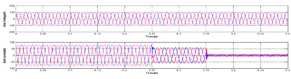 |
| Fig.5 Grid Voltage and current |
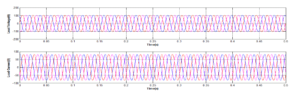 |
| Fig.6 Load Voltage and Current |
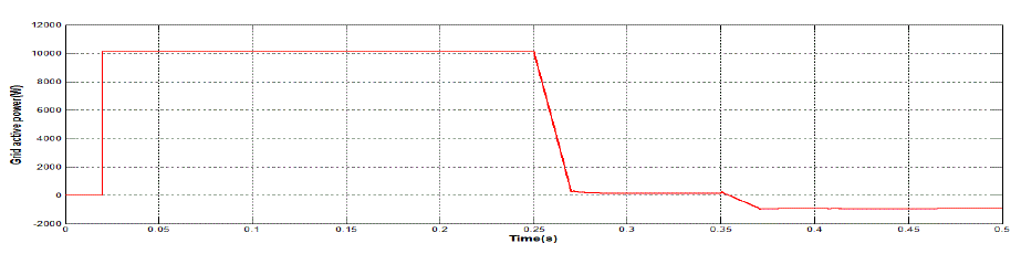 |
| Fig.7 Grid Active Power |
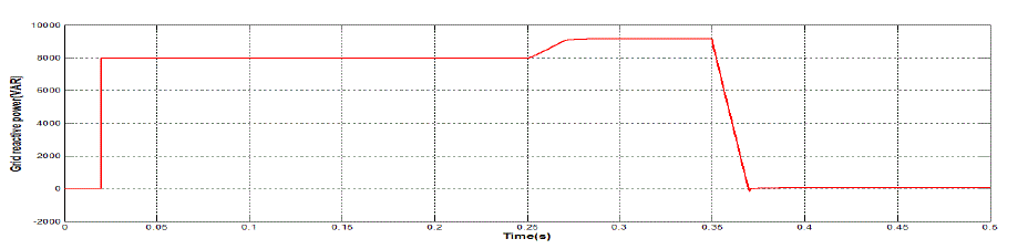 |
| Fig.8 Grid reactive power |
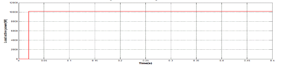 |
| Fig.9 Load active power |
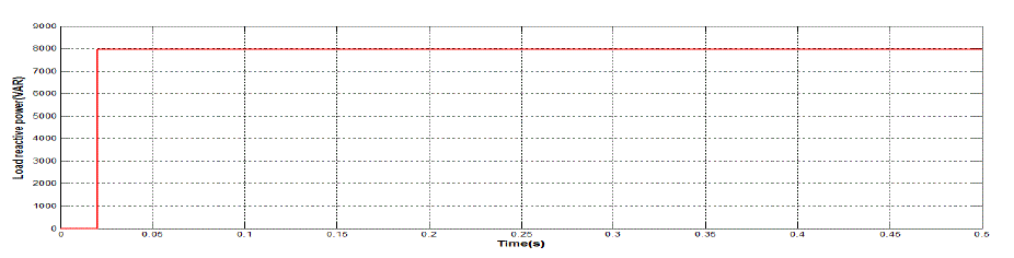 |
| Fig.10 Load reactive power |
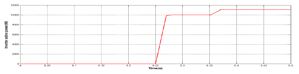 |
| Fig.11 Inverter active power |
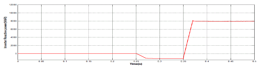 |
| Fig.12 Inverter Reactive Power |
| From time t=0 to 0.25 s, the inverter is not injecting power into the system. The active and reactive demand of the load is supplied from the grid. |
| At t=0.25 to 0.35 s inverter starts injecting active power to the system. So the grid active power demand reduces. From t= 0.35 inverter starts supplying reactive power demand along with the active power. Hence the grid reactive power value is reduced to zero. |
CONCLUSION
|
| A Solid Oxide Fuel Cell Distributed Generation system with grid interfacing inverter to improve the quality of power at PCC is modelled. Pulse Width Modulation (PWM) technique with dq reference template is used to generate gate pulses. The inverter is controlled to perform as a multi-function device by incorporating active power filter functionality. The voltage, current and power flow waveforms are obtained. Reactive power demand of the system is thus compensated. |
References
|
- Mukhtiar Singh, VinodKhadkikar ,Ambrish Chandra and Rajiv K. Varma,“Grid Interconnection of Renewable Energy Sources at theDistribution Level With Power-Quality Improvement Features”, , IEEE transactions on power delivery, vol. 26, no. 1, january 2011
- F. Blaabjerg, R. Teodorescu, M. Liserre, and A. V. Timbus, “Overview of control and grid synchronization for distributed power generationsystems,” IEEE Trans. Ind. Electron., vol. 53, no. 5, pp. 1398–1409,Oct. 2006.
- J. M. Carrasco, L. G. Franquelo, J. T. Bialasiewicz, E. Galván, R. C.P. Guisado, M. Á. M.Prats, J. I. León, and N. M. Alfonso, “Powerelectronic systems for the grid integration of renewable energy sources: A survey,” IEEE Trans. Ind. Electron., vol. 53, no. 4, pp. 1002–1016, Aug.2006.
- Bart Meersman, Bert Renders, LievenDegroote, Tine Vandoorn,Jeroen De Kooning and LievenVandevelde,” Overview of three-phase invertertopologies for distributed generation purposes” April 18-21,2010
- U. Borup, F. Blaabjerg, and P. N. Enjeti, “Sharing of nonlinear load in parallel-connected three-phase converters,” IEEE Trans. Ind. Appl.,vol.37, no. 6, pp. 1817–1823, Nov./Dec. 2001
- P. Jintakosonwit, H. Fujita, H. Akagi, and S. Ogasawara, “Implementation and performance of cooperative control of shunt active filters forharmonic damping throughout a power distribution system,” IEEE Trans. Ind. Appl., vol. 39, no. 2, pp. 556–564, Mar./Apr. 2003.
- Amin Hajizadeh† and MasoudAliakbarGolkar,” Power Flow Control of Grid-Connected Fuel Cell Distributed Generation Systems”, Journalof Electrical Engineering & Technology, Vol. 3, No. 2, pp. 143~151, 2008 143
- Mukesh Kumar Baliwal, 2Dr.A.Bhargava, 3Mr. S.N. Joshi,4Sunil kumar,” Modeling and Simulation of Solid Oxide Fuel Cell BasedDistributed Generation System”, International Journal of Engineering Research & Technology (IJERT)Vol. 2 Issue 8, August – 2013 IJERT ISSN:2278-0181
- F. Gonzalez-Longatt1,2, A. Hernandez2, F. Guillen1 and C. Fortoul3,” Load Following Function of Fuel Cell Plant in DistributedEnvironment”
- Schauder, H.Mehta,”Vector Analysis and control of advanced static VAR compensators”IEE proceedings-C,vol.140,No.4,july 1993.
|