Keywords
|
| International Electro-technical Commission (IEC), power quality, wind generating system (WGS). |
INTRODUCTION
|
| The causes of power quality problems are generally complex and difficult to detect when we integrate a wind turbine to the grid. Technically speaking, the ideal AC line supply by the utility system should be a pure sine wave of fundamental frequency (50/60Hz). We can therefore conclude that the lack of quality power can cause loss of production, damage of equipment or appliances or can even be detrimental to human health. It is therefore imperative that a high standard of power quality is maintained. This project demonstrates that the power electronic based power conditioning using custom power devices like P-STATCOM can be effectively utilized to improve the quality of power supplied to the customers. |
| Power quality and reliability cost the industry large amounts due to mainly sags and short-term interruptions. Distorted and unwanted voltage wave forms, too. And the main concern for the consumers of electricity was the reliability of supply. Here we define the reliability as the continuity of supply. The problem of distribution lines is divided into two major categories. First group is power quality, second is power reliability. First group consists of harmonic distortions, impulses and swells. Second group consists of voltage sags and outages. Voltage sags is much more serious and can cause a large amount of damage. If exceeds a few cycle, motors, robots, servo drives and machine tools cannot maintain control of process. |
| Transmission lines are exposed to the forces of nature. Furthermore, each transmission line has its load ability limit that is often determined by either stability constraints or by thermal limits or by the dielectric limits. Even though the power quality problem is distribution side problem, transmission lines are often having an impact on the quality of the power supplied. It is however to be noted that while most problems associated with the transmission systems arise due to the forces of nature or due to the interconnection of power systems, individual customers are responsible for more substantial fraction of the problems of power distribution systems. |
STATCOM
|
| In 1999 the first SVC with Voltage Source Converter called STATCOM (static compensator) went into operation. The STATCOM has a characteristic similar to the synchronous condenser, but as an electronic device it has no inertia and is superior to the synchronous condenser in several ways, such as better dynamics, a lower investment cost and lower operating and maintenance costs. |
| A STATCOM is build with Thyristors with turn-off capability like GTO or today IGCT or with more and more IGBTs. The static line between the current limitations has a certain steepness determining the control characteristic for the voltage. The advantage of a STATCOM is that the reactive power provision is independent from the actual voltage on the connection point. This can be seen in the diagram for the maximum currents being independent of the voltage in comparison to the SVC. This means, that even during most severe contingencies, the STATCOM keeps its full capability. |
| In the distributed energy sector the usage of Voltage Source Converters for grid interconnection is common practice today. The next step in STATCOM development is the combination with energy storages on the DC-side. The performance for power quality and balanced network operation can be improved much more with the combination of active and reactive power. |
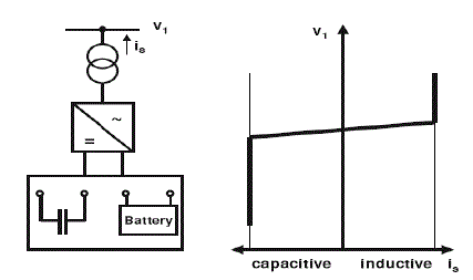 |
| Fig.1.STATCOM structure and voltage / current characteristic |
| STATCOMs are based on Voltage Sourced Converter (VSC) topology and utilize either Gate-Turn-off Thyristors (GTO) or Isolated Gate Bipolar Transistors (IGBT) devices. The STATCOM is a very fast acting, electronic equivalent of a synchronous condenser. |
| If the STATCOM voltage, Vs, (which is proportional to the dc bus voltage Vc) is larger than bus voltage, Es, then leading or capacitive VARS are produced. If Vs is smaller then Es then lagging or inductive VARS are produced. |
| 1) Exchange of reactive power:- If the output voltage of the voltage source converter is greater than the system voltage then the SATCOM will act as capacitor and generate reactive power(i.e.. provide lagging current to the system) |
| 2) Exchange of real power: - As the switching devices are not loss less there is a need for the DC capacitor to provide the required real power to the switches. For long duration of real power requirement even after the primary supply failed back up energy storage system (BESS) is used. Hence there is a need for real power exchange with an AC system to make the capacitor voltage constant in case of direct voltage control. There is also a real power exchange with the AC system if STATCOM is provided with an external DC source to regulate the voltage in case of very low voltage in the distribution system or in case of faults. |
TOPOLOGY FOR POWER QUALITY IMPROVEMENT
|
| The STATCOM based current control voltage source inverter injects the current into the grid in such a way that the source current are harmonic free and their phase-angle with respect to source voltage has a desired value. The injected current will cancel out the reactive part and harmonic part of the load and induction generator current, thus it improves the power factor and the power quality. To accomplish these goals, the grid voltages are sensed and are synchronized in generating the current command for the inverter. The proposed grid connected system is implemented for power quality improvement at point of common coupling (PCC). |
| The grid connected system in Fig. 1, consists of wind energy generation system and battery energy storage system with STATCOM. |
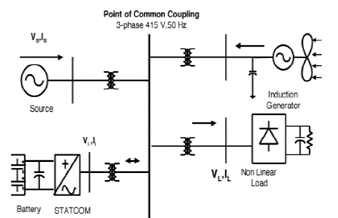 |
| Fig.2 Grid connected system for power quality improvement of Proposed System |
| In this configuration, wind generations are based on constant speed topologies with pitch control turbine. The induction generators used in the proposed scheme because of its simplicity, it does not require a separate field circuit, it can accept constant and variable loads, and has natural protection against short circuit. The available power of wind energy system is presented asunder the equation, |
 |
| It is not possible to extract all kinetic energy of wind, thus it extract a fraction of power in wind, called power coefficient Cp of the wind turbine, and is given in eq |
 |
| A.BESS-STATCOM |
| The battery energy storage system (BESS) is used as an energy storage element for the purpose of voltage regulation. The BESS will naturally maintain dc capacitor voltage constant and is best suited in STATCOM since it rapidly injects or absorbed reactive power to stabilize the grid system. It also control the distribution and transmission system in a very fast rate. When power fluctuation occurs in the system, the BESS can be used to level the power fluctuation by charging and discharging operation. The battery is connected in parallel to the dc capacitor of STATCOM. |
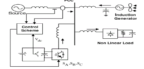 |
| Fig 3 System operational scheme in grid system. |
| The shunt connected STATCOM with battery energy storage is connected with the interface of the induction generator and non-linear load at the PCC in the grid system. The STATCOM compensator output strategy, so as to maintain the power quality norms in the gridy stem. The current control strategy is included in the control scheme that defines the functional operation of the STATCOM compensator in the power system. A single STATCOM using insulated gate bipolar transistor is proposed to have a reactive power support, to the induction generator and to the non linear load in the grid system. |
SIMULATION RESULTS
|
| A. Simulation Model |
| Wind generation using wind turbine, pitch control, Induction Generator. Here we are using the induction generator as generating machine due to its advantages over other machines for its simplicity and economical factors. The pitch angle controller makes the angle of the turbine blade to adjust in such a way that the speed of rotation at every velocity of the wind is maintained constant. And the parallel capacitive bank is to supply the reactive power to the IM running as the generator. Here we considered the per unit values in the closed loop that can be seen from the fig 6.9. The rms values of the current and voltage generated is taken and the power is being calculated at every sampling time interval and the wave form is being traced in the scope. A timer is used in fig for assigning the wind velocity at 3 different states which will be linearise after some loop operations. |
| B. PARAMETERS |
| Grid voltage 415 V. |
| Operating frequency 60 HZ. |
| Induction generator 3.35KVA, |
| 415V, 60 Hz, Speed 1440rpm, |
| Rr 0.01Ω, |
| Rs 0.015Ω, |
| Ls=Lr 0.06H. |
| Inverter - DC Link Voltage 800V, DC Link Capacitance 100μF, |
| Switching Frequency 2 kHz. |
| Non linear load 25 KW. |
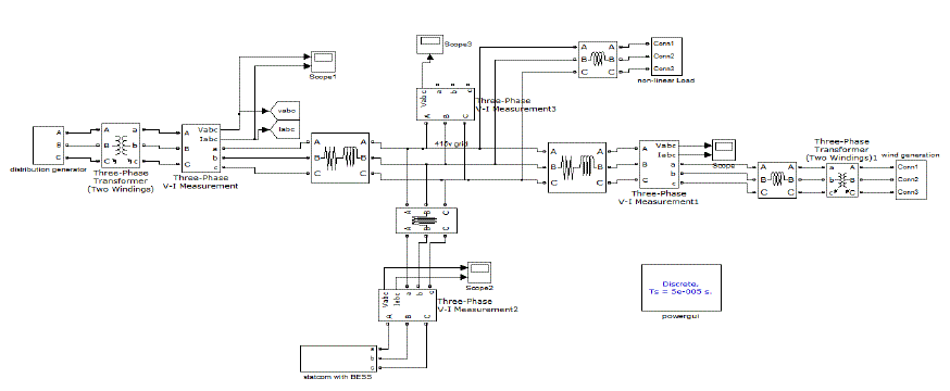 |
| Fig 4 Over all circuit diagram in simulink with sub systems |
| C.Results |
 |
| Fig 5 grid voltage without statcom |
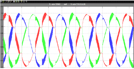
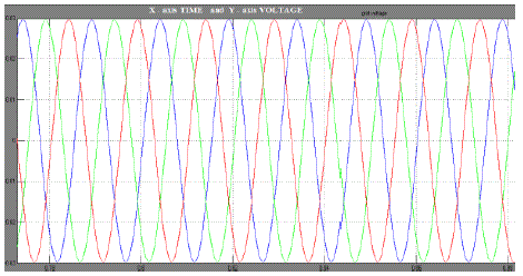
| Fig.5 shows the grid voltage waveform before the incorporation of STATCOM which gives low voltage of around 0.02 pu where the actual value should be 0.0301 pu(415 V/ 13.8 KV = 0.0301 p.u and this is obtained by the incorporation of STATCOM in the circuit and the power quality is under control. This result is shown in Fig.6. |
 |
| Fig 6 compensated grid voltage |
CONCLUSION
|
| In this paper we present the FACTS device (STATCOM) -based control scheme for power quality improvement in grid connected wind generating system and with nonlinear load. The power quality issues and its consequences on the consumer and electric utility are presented. The operation of the control system developed for the STATCOM in MATLAB/SIMULINK for maintaining the power quality is to be simulated. It has a capability to cancel out the harmonic parts of the load current. It maintains the source voltage and current in-phase and support the reactive power demand for the wind generator and load at PCC in the grid system, thus it gives an opportunity to enhance the utilization factor of transmission line. |
| Thus the integrated wind generation and FACTS device with BESS have shown the outstanding performance in maintaining the voltage profile as per requirement. Thus the proposed scheme in the grid connected system fulfils the power quality requirements and maintains the grid voltage free from distortion and harmonics. |
References
|
- A.Sannino,“Global power systems for sustainable development,” in IEEE General Meeting, Denver, CO, Jun. 2004.
- K.S. Hook, Y.Liu, and S. Atcitty,”Mitigation of the wind generation integration related power quality issues by energy storage,” EPQU J., vol. XII, no.2, 2006.
- J.Manel, “Power electronic system for grid integration of renewable energy source: A survey,”IEEE Trans. Ind. Electron., vol. 53, no. 4,pp. 1002-1014,2006, Carrasco.
- M. Tsili and S. Papathanassiou,” A review of grid code technology requirements for wind turbine,” Proc. IET Renew.power gen., vol. 3, pp. 308-332,2009.
- A.E. Hammad, Comparing the Voltage source capability of Present and future Var Compensation Techniques in Transmission System, IEEE Trans, onPower Delivery. Volume 1.No.1 Jan 1995.
- G.Yalienkaya, M.H.J Bollen, P.A. Crossley, “Characterization of Voltage Sags in Industrial Distribution System”, IEEE transactions on industryapplications, volume 34, No. 4, July/August, PP.682- 688, 1999.
- Haque, M.H., “Compensation of Distribution Systems Voltage sags by DVR and D-STATCOM”, Power Tech Proceedings, 2001 IEEE Porto, Volume1, PP.10-13, September 2001.
- Anaya-Lara O, Acha E., “Modeling and Analysis Of Custom Power Systems by PSCAD/EMTDC”, IEEE Transactions on Power Delivery, Volume17, Issue: 2002, Pages: 266-272.
- Bollen, M.H.J.,”Voltage sags in Three Phase Systems”, Power Engineering Review, IEEE, Volume 21, Issue: 9, September 2001, PP: 11-15.
- V.Kumar and J.Karpagam,” Control Techniques for Multilevel Voltage Source Inverters, IPEC” vol. 5, pp.978-981, 2007.
- K.Malarvizhi and K.Baskaran,” Enhancement of Voltage Stability in Fixed Speed Wind Energy Conversion Systems using FACTS Controller”,International Journal of Engineering Science and Technology, vol. 2, No. 4, pp.1800-1810, 2010.
- Fu.SPai and S.I Hung, ” Design and operation of converter for micro Turbine Powered distributed generator with capacity expansion capability”,IEEE Transactions on Energy Conversion., vol. 3, No. 1, pp. 110–116,2009.
|