Keywords
|
| Power quality, Voltage sag, DVR, SRF theory, Self supported DVR |
INTRODUCTION
|
| The electric power utilities must provide their consumers with uninterrupted sinusoidal voltage at the desired magnitude and frequency. Recent technological advancements have led to a rapid growth in the number of nonlinear loads present in the power distribution system which adversely affects the quality of power supply. These nonlinear loads distort the supply voltage waveform. This results in various power quality disturbances [1]. |
| Most of the electronic devices used today are sensitive to the power disturbances and hence are more susceptible to degradation of power quality. For some of the sophisticated devices, a momentary disturbance can lead to scrambled data, communication interruptions, system crashes and failure of equipment [2]. Power Quality problems include disturbances like voltage sags, voltage swells, voltage unbalance, harmonics, power frequency variations, flicker, impulse transient and interruptions. Voltage sags are recognized as the most frequent, severe and costly power quality problem damaging sensitive loads. According to IEEE Standard 1100-1992, sag is ` a reduction in the rms value of AC voltage, for durations from 0.5 cycles to about 1 minute, at the power frequency [1]. |
| For improving power quality and system reliability, a new category of devices known as custom power devices are introduced. The most commonly used custom power devices in the distribution side are Dynamic Voltage Restorer (DVR), Distribution Static Synchronous Compensator (DSTATCOM), Active Filter (AF) and Unified Power Quality Conditioner (UPQC) [3]. DVR is the most effective solution for compensating voltage sag and swell from the point of view of economy and efficiency. DVR also possesses additional features like compensation of line voltage harmonics, fault current limitation and reduction of voltage transients [2]. |
| In this paper, effectiveness of two different configurations of DVR - the battery supported and self supported DVR - in power quality improvement are studied through simulations in PSCAD/EMTDC software. The adopted control strategy combines Synchronous Reference Frame (SRF) method for voltage sag detection and the method of unit vectors for reference voltage generation. |
DYNAMIC VOLTAGE RESTORER
|
| A. Basic Configuration and Operation |
| DVR is a device that keeps the load side voltage undisturbed by injecting voltage into the system. It is generally installed in series with the distribution system at the point of common coupling between the supply and the critical load feeder. Fig.1 shows the basic components and connection of a DVR. |
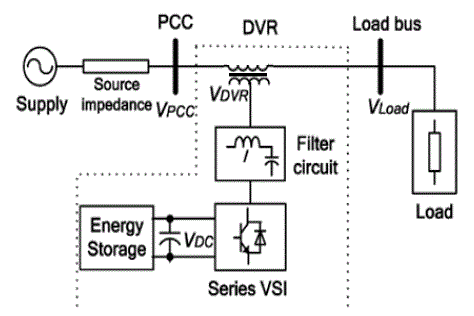 |
| Fig. 1. Basic DVR topology |
| A sag in the system voltage is identified by the control circuitry of DVR which in turn generates the firing pulses for the inverter. The voltage to be injected into the system is generated by the inverter which is coupled to the distribution system via the injection transformer. The harmonic contents in the inverter output are filtered out by a harmonic filter. The DC source is used for satisfying the real power requirement for voltage sag compensation [3]. |
POWER CIRCUIT TOPOLOGIES FOR DVR
|
| Power circuit topologies for DVR are broadly classified into two; one uses stored energy and the other uses no significant energy storage [4,5]. The system topologies are; |
| 1. Topologies with stored energy |
| i. Constant DC-link voltage |
| ii. Variable DC-link voltage |
| 2. Topologies with power from the supply |
| i. Supply side connected passive shunt converter |
| ii. Load side connected passive shunt converter |
| Among these, the DVR configuration with stored energy is discussed in this paper. The topologies with constant DC link voltage as well as variable DC link voltage are discussed below. |
| A. Constant DC-link voltage |
| A DVR with constant DC-link voltage illustrated in fig. 2 is expected to have superior performance and an effective utilization of the energy storage. An additional converter is expected to convert energy from the main storage to a small DC-link and thereby control and stabilize the DC-link voltage. The stored energy can be delivered from different kinds of energy storage systems such as batteries, flywheel storage or SMES. The DVR with a constant voltage is here considered to be a reference topology by which the other DVR topologies are evaluated. It offers a constant DC-link voltage at all times and does not increase the current drawn from the supply. This configuration is also known as Battery Supported DVR as the DC link voltage is always constant [5]. |
| The performance of this system is improved compared to the variable DC link solution, but the equipment costs are higher as energy storage is needed and a separate high-rated power converter is necessary [4]. |
| B. Variable DC link voltage |
| The DVR with variable DC-link voltage is illustrated in fig. 3. It offers benefits in simplicity due to only one high rated converter and only DC-link capacitors as the energy storage. The voltage injection capacity depends on the actual level of the DC-link voltage and energy saving control strategies are urgent to fully utilize the energy storage system. As this DVR configuration is capable of compensating power quality problems with the help of its self supporting DC bus, this type is generally referred to as Self Supported DVR. The DC-link voltage can be utilized only down to a certain DC-link voltage level. Hence, the range of power disturbances that can be compensated by this type of DVR configuration is limited [4,5]. |
 |
CONTROL STRATEGY
|
| A. Control of Self Supported DVR |
| The control algorithm for self supported DVR is based on the principle of unit vectors and instantaneous symmetrical component theory for fundamental voltage extraction [6,7]. The block diagram of the control system is shown in fig. 4. Voltage sag, swell and harmonics can be compensated using this technique. |
| The voltages at PCC (Vabc), load currents (IL), load voltages (VL) and DC voltage (VDC) are sensed for deriving the Insulated Gate Bipolar Transistor (IGBT) gate signals. The reference load voltage (VL *) is derived as |
 |
| Where VLa* is the reference load voltage of phase A in abc frame. Vta1 is the fundamental positive sequence voltage [8, 9]. Vad corresponds to required active voltage component of phase A for self supporting DC bus. Vaq is the required reactive voltage component for voltage regulation at load terminal. Reference load voltage of the remaining phases can be determined similarly. |
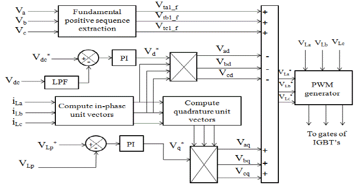 |
| Fig. 4 Control block diagram of self supported DVR |
| The active and reactive components of the voltage to be injected by the DVR are estimated using two PI controllers. In phase unit vectors are derived using samples of load current as, |
 |
| Two Proportional Integral (PI) controllers are used for regulating the DC bus voltage and the load voltage to their reference values. The reference load voltage and sensed load voltages are fed to the PWM controller for generating the gate pulses for the converter switches [7]. |
| B. Control of Battery Supported DVR |
| The control block diagram of battery supported DVR is shown in fig. 5. The system employs SRF transformations and method of unit vectors for reference signal estimation [7]. The voltages at the PCC, Vs and load terminal VL are sensed for deriving the IGBT gate signals. The reference load voltage VL* is extracted using the derived unit vector [10]. |
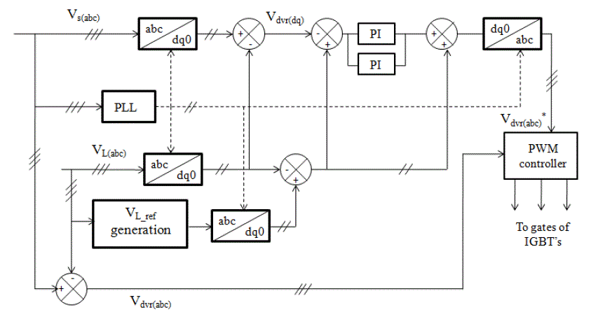 |
| Fig. 5 Control block diagram of battery supported DVR |
| Initially, the sensed source voltage, actual load voltage and reference load voltage are converted to the rotating reference frame using abc - dq0 conversion. The actual DVR voltage in the dq frame is the difference between the source and load voltage in dq frame [10]. |
 |
| The reference DVR voltages are obtained in the rotating reference frame as the difference between reference and actual load voltage. |
 |
| The error between the reference and actual DVR voltages in the rotating reference frame is regulated using two PI controllers. By applying dq0-abc transformation to this regulated error, the reference DVR voltage in the abc frame (Vdvra, Vdvrb and Vdvrc) is obtained. The transformation equation is, |
 |
| Where, vDd*, vDq* and vD0* are the dq0 components of regulated error voltage. Reference DVR voltages (Vdvra*, Vdvrb* and Vdvrc*) and actual DVR voltages (Vdvra, Vdvrb and Vdvrc) are used in a PWM controller to generate gating pulses to the VSI [10]. |
SIMULATION ANALYSIS
|
| The simulations are carried out in PSCAD/EMTDC software. Test system is a 3 phase 415 V system with a load of 8 kVA, 0.8 p.f lag. The PSCAD implementation of the test system is shown in fig. 6. The DVR consists of three single phase injection transformers connected in series with the line and three single phase H-bridge inverters one for each phase. The inverter is supplied from an ac source-rectifier assembly in case of battery supported type and no energy storage other than DC link capacitor is present in self supported type. |
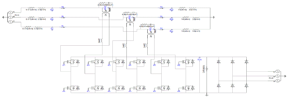 |
| Fig. 6. PSCAD implementation of the test system with battery supported DVR |
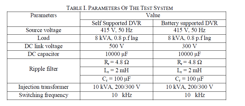
| The system parameters for battery supported and self supported configuration are summarized in table I. |
 |
| A. Simulation Results of Self Supported DVR |
| The performance of the self supported DVR with the specified control mechanism is simulated for four different power quality disturbances; balanced voltage sag/swell and unbalanced voltage sag/swell. |
| a) Three Phase Voltage Sag |
| A three phase fault is generated at 0.3s and sustained for 0.1s to obtain the three phase voltage sag. The three phase source voltages are reduced by 50% for the time interval of 100 ms. The source voltage, load voltage, injecting voltage and DC link voltage are shown in fig. 7. |
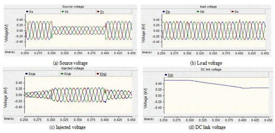 |
| Fig. 7. Simulation results under a three phase voltage sag with depth of 50% for a duration of 0.1 sec with self supported DVR |
| b) Single Phase Voltage Sag |
| A single phase fault is initiated at the instant t=0.3s and sustained for 0.1s. As a result of the fault, phase A voltage undergone a sag of about 50% depth. Relevant waveforms are shown in fig. 8. |
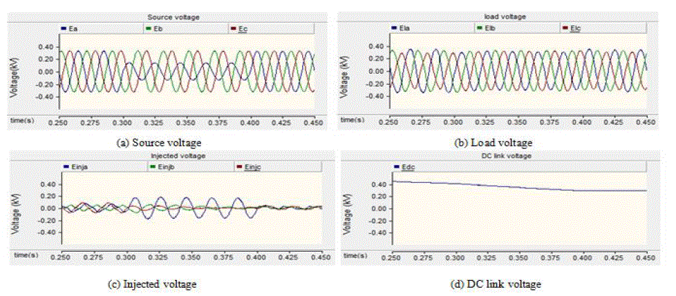 |
| Fig. 8. Simulation results under a single phase voltage sag with depth of 50% for a duration of 0.1 sec with self supported DVR |
| c) Three Phase Voltage Swell |
| A capacitor bank is switched to the system during the interval 0.3-0.4s which resulted in a voltage rise in the system voltage. The source voltage, load voltage, injected voltage and the DC link voltage are shown in fig. 9. |
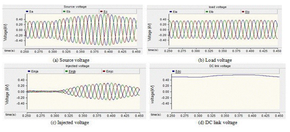 |
| Fig. 9. Simulation results under a three phase voltage swell for a duration of 0.1 sec with self supported DVR |
| d) Single Phase Volatge Swell |
| A capacitor is switched to phase A of the system during the interval 0.3-0.4 sec which resulted in a voltage rise in phase A. The source voltage, load voltage, injected voltage and the DC link voltage are shown in fig. 10. |
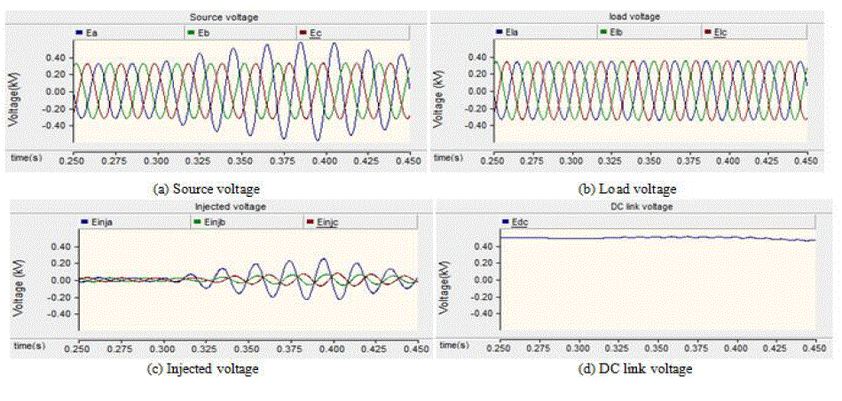 |
| Fig. 10. Simulation results under a single phase voltage swell for a duration of 0.1 sec with self supported DVR |
| B. Simulation Results of Battery Supported DVR |
| a) Three Phase Voltage Sag |
| Three phase sag of 50% depth is generated in the interval 0.3 -0.4 sec. The source voltage, load voltage, injecting voltage and DC link voltage are shown in fig. 11. |
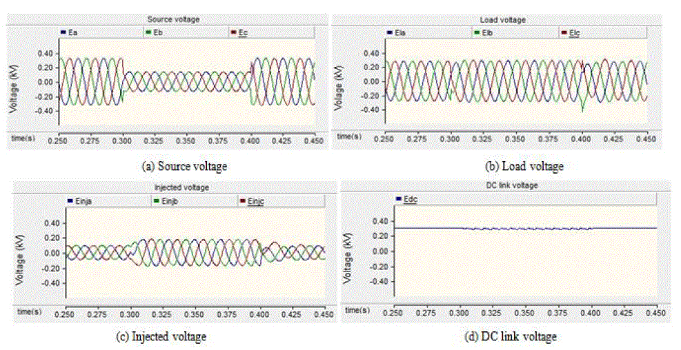 |
| Fig. 11. Simulation results under a three phase voltage sag of 50% depth for a duration of 0.1 sec with battery supported DVR |
| b) Single Phase Voltage Sag |
| A single phase fault is initiated at the instant t=0.3s and sustained for 0.1s. As a result of the fault, phase A voltage undergone a sag of about 50% depth. Relevant waveforms are shown in fig. 12. |
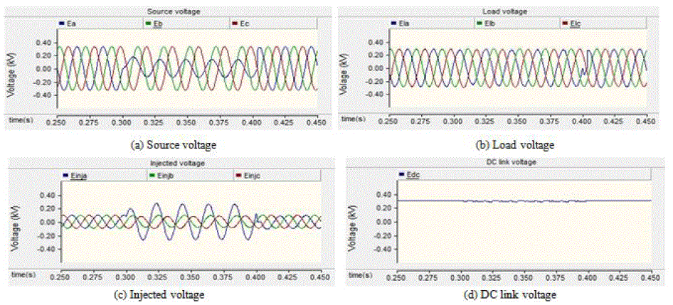 |
| Fig. 12. Simulation results under a single phase voltage sag of 50% depth for a duration of 0.1 sec with battery supported DVR |
| c) Three Phase Voltage Swell |
| A capacitor bank is switched to the system during the interval 0.3-0.4s which resulted in a voltage rise in the system voltage. The source voltage, load voltage, injected voltage and the DC link voltage are shown in fig. 13. |
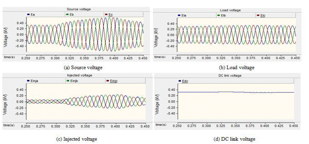 |
| Fig. 13. Simulation results under a three phase voltage swell for a duration of 0.1 sec with battery supported DVR |
| d) Single Phase Voltage Swell |
| A capacitor is switched to phase A of the system during the interval 0.3-0.4 sec which resulted in a voltage rise in phase A. The source voltage, load voltage, injected voltage and the DC link voltage are shown in fig. 14. |
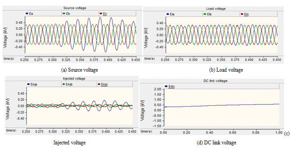 |
| Fig. 14. Simulation results under a three phase voltage swell for a duration of 0.1 sec with battery supported DVR |
CONCLUSION
|
| The battery supported DVR regulates the DC link voltage to a constant value whereas self supported type gives a variable DC link voltage. The former type is capable of compensating deeper voltage sags by extracting active power from its external storage. But, the sag depth that can be compensated by the self supported type is limited as it has no means for energy storage other than the DC link capacitor. Long duration events can be compensated by battery supported DVR more effectively than self supported type. Because, in the latter configuration, DC link voltage decays after some time. Both the configurations described in this paper are capable of compensating symmetrical as well as non symmetrical voltage disturbances. The Battery supported DVR system is more complex as it requires two high rated converters. While self supported type has a simple structure with only one high rated converter. |
References
|
- P. Roncero-Sánchez, E. Acha, J. E. Ortega-Calderon, V. Feliu, and A. García-Cerrada, “A versatile control scheme for a dynamic voltage restorerfor power-quality improvement,” IEEE Trans. Power Del., vol. 24, no. 1, pp. 277–284, Jan. 2009.
- I. Chung, S. Park, S. Moon, and S. Hur, “The control and analysis of zero sequence components in DVR system,” in Proc. IEEE Power Eng. Soc.Winter Meeting, 2001, pp. 1021–1026.
- J. G. Nielsen, F. Blaabjerg, and N. Mohan, “Control strategies for dynamic voltage restorer compensating voltage sags with phase jump,” in Proc.IEEE APEC, pp. 1267–1273, May 2001.
- J. G. Nielsen, F. Blaabjerg, `A Detailed Comparison of System Topologies for Dynamic Voltage Restorers', IEEE Transactions on IndustryApplications, 41(5), 2005.
- J. G Nielsen, `Design and Control of a Dynamic Voltage Restorer', Ph. D Thesis, Aalborg University, Denmark, 2002.
- ParagKanjiya, Bhim Singh, `A Robust Control Algorithm for Self Supported Dynamic Voltage Restorer', IEEE India International Conferenceon Power Electronics, 1-8, 2011.
- Bhim Singh, P. Jayaprakash, `Indirect Control of Capacitor Supported DVR for Power Quality Improvement in Distribution System', IEEEConference on Power and Energy, 1-7, 2008.
- ParagKanjiya, VinodKhadkikar, `Reactive Power Estimation based control of Self Supported Dynamic Voltage Restorer', InternationalConference on Harmonics and Quality of Power, 785-790, 2012.
- ParagKanjiya, Bhim Singh, SRF Theory Revisited" to Control Self Supported Dynamic Voltage Restorer for Unbalanced and Nonlinear Loads,2011.
- P. Jayaprakash, Bhim Singh, `Control of Reduced-Rating Dynamic Voltage Restorer with a Battery Energy Storage System', IEEE Transactionson Industry Applications, 50(2), 1179- 1190, 2014.
|