Keywords
|
| Active power filter (APF), harmonic compensation, power quality, reactive power compensation, unified power quality conditioner (UPQC) |
INTRODUCTION
|
| Some major concerns of power quality problems are poor load power factor, harmonic contents in load, notching in load voltage, DC offset in load voltage, unbalanced loads, supply voltage distortion, voltage sag/swell, voltage flicker etc.The growing use of electronic equipment produces a large amount of harmonics in the power distribution systems because of non-sinusoidal currents consumed by nonlinear loads. Some of the examples for non -linear loads are diode-rectifiers, thyristor converters, adjustable speed drives, furnaces, computer power supplies, uninterruptible power supplies etc. These devices are much economical, flexible and energy efficient, but they are responsible for the degradation of power quality by producing harmonic current and consuming excessive reactive power which results in many problems such as resonance, excessive neutral currents, low power factor etc. They have many unwanted negative impact on power system equipments such as additional losses in overhead and underground cables, transformers and rotating electric machines, problem in the operation of the protection systems, error of measuring instruments, and malfunction of low efficiency of customer sensitive loads. Traditionally passive filters have been used for mitigation of distortion due to harmonic current in industrial power systems. They did not become popular because they had many drawbacks such as resonance problem , performance dependence on the system impedance, absorption of harmonics current of nonlinear load, which could lead to further harmonic propagation through the power system. To overcome the problems associated with the passive filter active power filters were introduced in practical system applications . |
| Active power filters (APFs) that have been explored in shunt, series and combination of shunt and series configurations to compensate for current and voltage based distortions .It will play an important role for better quality solutions . |
| Conventional power quality mitigation equipment is proving to be inadequate for applications, and this fact has attracted the attention of power engineers to develop dynamic and adjustable solutions to power quality problems. Thus, between the different technical options available to improve power quality, Active Power Filters (APFs) have proved to be an important alternative to minimize the financial impacts of PQ problems. |
| Unified Power Quality Conditioner (UPQC) is one of the modern and very promising PQ improving device, which consists of two APFs connected back-to-back on the DC side and deals with both load current and supply voltage imperfections. |
| The main purpose of a UPQC is to compensate for voltage flicker/imbalance, reactive power, negative-sequence current, and harmonics. In other words, UPQC has the capability of improving power quality at the point of installation on the power distribution systems or industrial power system[3]. |
UPQC
|
| Figure:1 shows a single-line representation of the UPQC system configuration. |
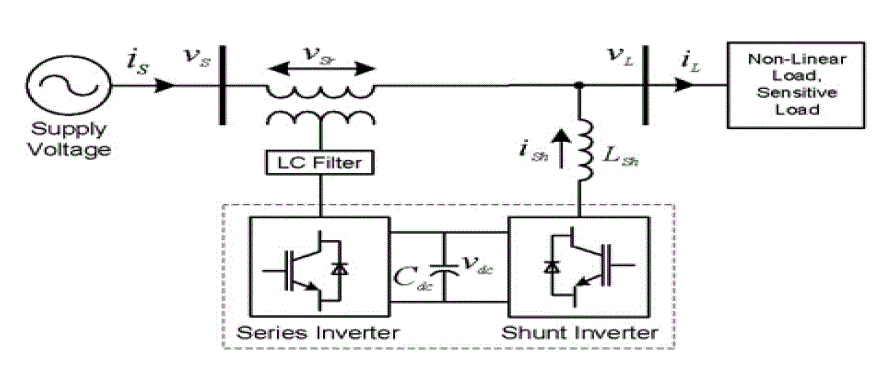 |
| Fig.1: UPQC general block diagram representation |
| UPQC consists of two voltage source converter. They are operated from a common dc link provided by a dc storage capacitor. One converter is connected across the line referred as shunt converter and the other which is connected in series with the line referred as series converter. Shunt coupling inductor LSh is used to interface the shunt inverter to the network. It also helps in smoothing the current wave shape. Sometimes an isolation transformer is utilized to electrically isolate the inverter from the network. In Fig.1, the dc link is realized using a capacitor which interconnects the two inverters and also maintains a constant self-supporting dc bus voltage across it. An LC filter that serves as a passive low-pass filter (LPF) helps to eliminate high-frequency switching ripples on generated inverter output voltage. A series injection transformer is used to connect the series inverter to the network. A suitable turn ratio is often considered to reduce the current or voltage rating of the series inverter [2]. |
| UPQC is an integration of shunt and series APFs with a common self-supporting dc bus. The shunt inverter in UPQC is controlled in current control mode such that it delivers a current which is equal to the set value of the reference current as governed by the UPQC control algorithm. Additionally, the shunt inverter plays an important role in achieving required performance from a UPQC system by maintaining the dc bus voltage at a set reference value. In order to cancel the harmonics generated by a nonlinear load, the shunt inverter should inject a current as governed by following equation: |
 |
 |
| Where, VSr (ωt), V* L(ωt) and VS(ωt) represent the series inverter injected voltage, reference load voltage, and actual source voltage, respectively.The arrangement functions an ideal ac-to-ac power converter in which the real power can freely flow in either direction between the ac terminals of the two converter, and each converter can independently generate or absorb reactive power at its own ac output terminal. |
SYNCHRONOUS REFERENCE THEORY (SRF)
|
| In the SRF ,a time varying angle represents the angular position of the reference frame which is rotating at constant speed in synchronism with the three phase ac voltages. To implement the SRF method some kind of synchronizing system should be used. A phase-locked loop (PLL) can be used for the implementation of this method. In this case the speed of the reference frame is practically constant, that is, the method behaves as if the reference frame’s moment of inertia is infinite. The fundamental currents of the d-q components are now dc values. The harmonics appear like ripple. Harmonic isolation of the d-q transformed signal is achieved by removing the dc offset. This is accomplished using high pass filters (HPF). In spite of a high pass filter, a low pass filter is used to obtain the reference source current in d -q coordinates[6]. |
| Direct–quadrature–zero (d-q-o) transformation is a mathematical transformation that rotates the reference frame of three-phase systems in an effort to simplify the analysis of three phase circuits. In the case of balanced three-phase circuits, application of the d-q-o transformation reduces the three AC quantities to two DC quantities. Simplified calculations can then be carried out on these DC quantities before performing the inverse transform to recover the actual three-phase AC results. The power-invariant, right-handed d-q-o transformation applied to any three-phase quantities (e.g. voltages, currents, flux linkages, etc.) is shown below in matrix form. |
 |
BASIC CONTROL FUNCTION
|
| UPQC should separate out the fundamental frequency positive sequence components first from the other components. Then it is required to control both series and shunt active filter to give the required compensation[1].The control strategy uses a PLL based unit vector template for extraction of reference signal from the distorted input supply. The block diagram of extraction of unit vector template is as given in Figure: 2. |
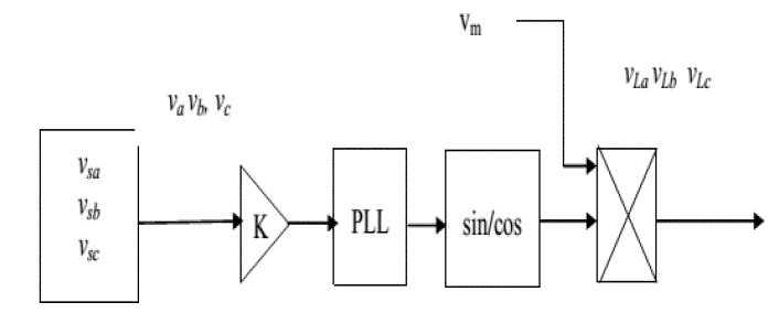 |
| Fig 2: Extraction of unit vector template |
| The input source voltage at point of common coupling contains fundamental and distorted component. To get unit vector templates of voltage, the input voltage is sensed and multiplied by gain equal to 1/vm, where vm is peak amplitude of fundamental input voltage. These unit vector templates are then passed through a PLL for synchronization of signals. The unit vector templates for different phases are obtained as follows: |
 |
 |
 |
| A. Shunt converter control |
| The unit vector template of voltage is used to generate the reference signal for shunt APF. The control block diagram of shunt active filter is given in Figure:3. As indicated earlier, the shunt APF compensates current harmonics in addition to maintaining the dc link current at a constant level. To achieve this, dc link current of the UPQC is compared with a constant reference current of magnitude equal to peak of harmonic current . The error between measured dc link current and reference current is processed in a PI controller. The output of PI controller is added to real power loss component to derive reference source current Iar, Ibr, Icr as shown in Figure:3. |
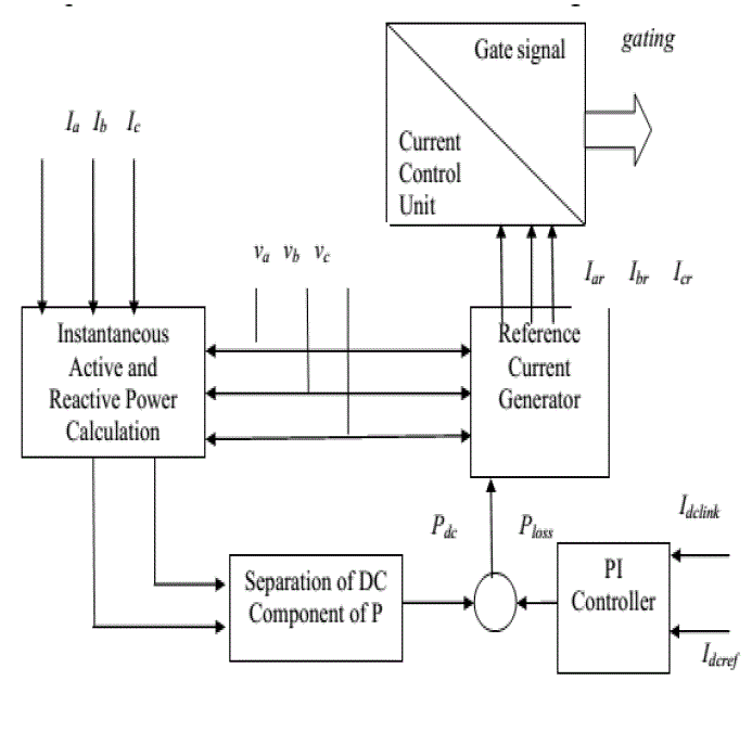 |
| Fig.3 Control block of shunt filter controller |
| B. Series converter control |
| In order for the load voltage to be perfectly sinusoidal and balanced, the series filter should produce the required compensated voltage . The reference load voltages are obtained by multiplying the unit vector templates with a constant equal to peak amplitude of fundamental input voltage. The compensation signals for series filter are thus obtained by comparing these reference load voltages with actual source voltage using equations given below[5]. |
 |
MATLAB/SIMULINK MODEL AND SIMULATION RESULTS
|
| Simulink Model of UPQC worked out in MATLAB R2010a is shown in Figure:4(a). Operation of UPQC under different kinds of load such as RC,RL and non-linear loads are carried out here. Simulation results are shown in Figure:4 (b),(c) and in Figure:5. |
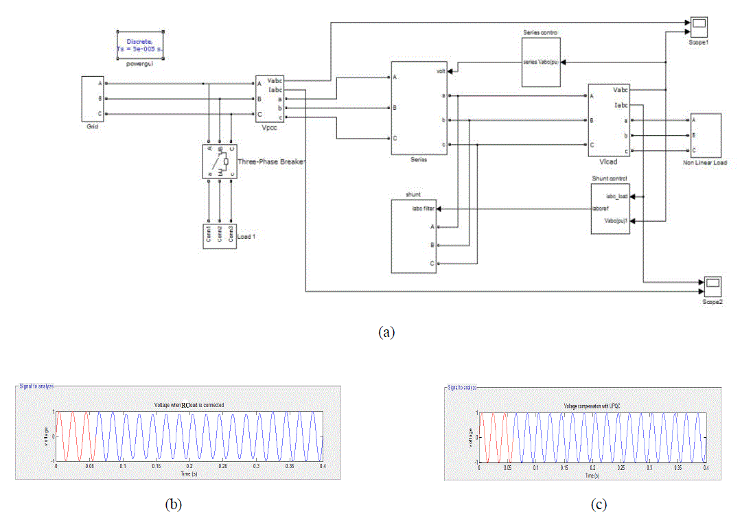 |
| Fig 4: (a) SIMULINK Model of UPQC (b) Voltage when RC load is connected (c) Compensated Voltage with UPQC |
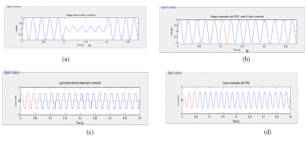 |
| Fig 5: (a) Voltage when for RL load (b)Voltage compensation with UPQC (c) Current when non-linear load is connected (d) Current Compensation with UPQC |
| Operation of UPQC under different load condition such as RL ,RC and non-linear loads are carried out. Figure: 4(b) shows the voltage variation when RC load is connected to the system. Load is connected at the instant between .1sec and .3secs.At that time voltage is reduced from 1volt to .8volt. Figure:4(c) shows the voltage compensation with UPQC when RC load is connected. It maintains the voltage constant even under load changed conditions. Figure:5(a) shows the voltage variation when RL load is connected to the system. Load is connected at the instant between .1sec and .2secs.At that time voltage is reduced from 1volt to .4volt.Figure:5(b) shows the voltage compensation with UPQC when RC load is connected. It maintains the voltage constant irrespective of load. Figure:5(c) shows the harmonic distortion in current when non-linear load is connected. Figure:5(d) shows the current compensation provided by UPQC. With UPQC compensation a pure sinusoidal waveform is obtained. |
 |
| Fig 6: SIMULINK Model of power system with passive filter |
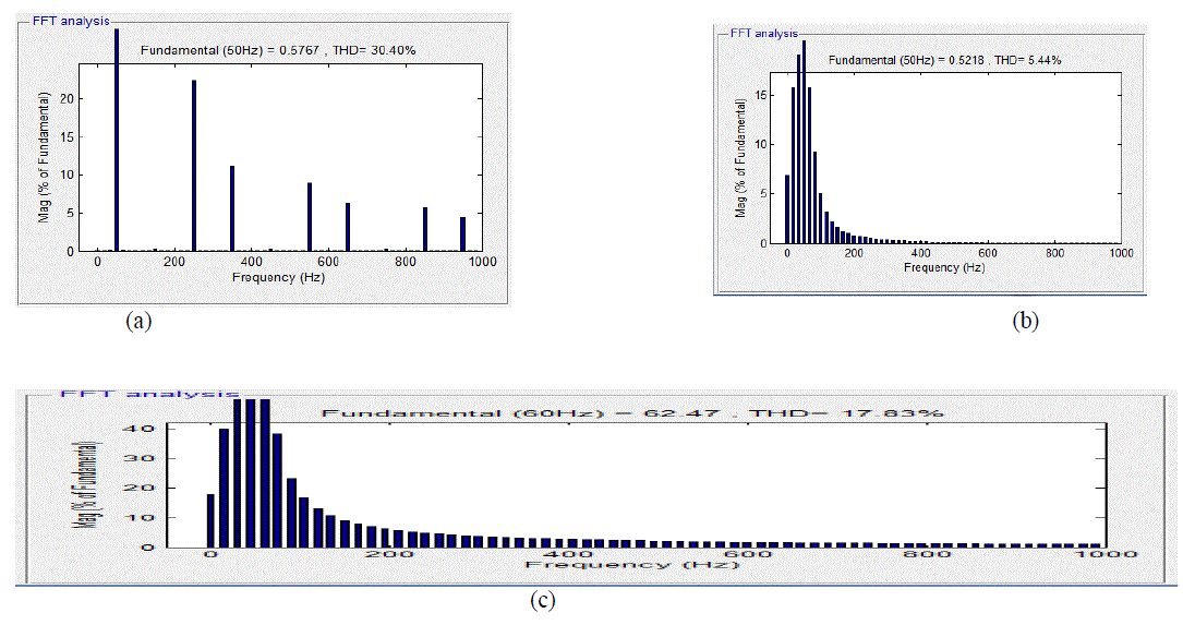 |
| Fig:7 (a) THD when non-linear load is connected (b) THD with UPQC (c)THD with passive filter |
| Figure :7(a) shows the total harmonic distortion(THD) variation in line when non-linear load is connected to the system.Figure:7(b) and 7(c) shows the THD reduction with UPQC and passive filter. UPQC reduces THD in line current to 5% from 31% and passive filter reduces the THD to 20%. |
| Passive filter reduces the harmonics in the line. But disadvantages of passive filter are it results in resonance with the source impedance and it gives fixed compensation. But UPQC provide better compensation for voltage and current and reduces the harmonics in the line significantly. The total harmonic distortion analysis of power system with UPQC and passive LC filter is given in the Table.I |
| Table I PERFORMANCE OF UPQC AND PASSIVE FILTER |
 |
CONCLUSION
|
| UPQC is used to enhance the electric power quality at distribution level. UPQC is concerned about the quality of load voltage and the line current at the point of installation and it does not improve the power quality of entire system. The performance of UPQC has been studied under different cases of R-L, R-C loads and non-linear loads. Also a comparative study on the performance of UPQC and passive filter on the suppression of current harmonics when nonlinear load connected is also carried out. |
| UPQC maintains the voltage constant under varying RLC load conditions. Therefore it provides better voltage regulations in switching of loads and improvement in the real and reactive power flow through the transmission line. With UPQC compensation , the harmonic distortion in line current when non-linear load connected is around 5% . |
| But with passive filter, THD is about 20% . UPQC reduces the THD by 15 percent compared to passive filter. So UPQC is well effective in active filtering, improvement of power quality and power factor. |
References
|
- Sai Shankar, Ashvani Kumar,” Operation of Unified Power Quality Conditioner under Different Situations” , 978-1-4577-1002-5/11/$26.00 ©IEEE 2011.
- VinodKhadkikar, “Enhancing Electric Power Quality Using UPQC:A Comprehensive Overview”, IEEE transactions on Power Electronics,VOL. 27, NO. 5, MAY 2012.
- H. Fujita and H. Akagi, “The unified power quality conditioner: The Integration of series- and shunt active filters”, IEEE Trans. PowerElectronics, vol. 13, no. 2, pp. 3 15-322, 1998.
- R. Rezaipour and A. Kazemi, “Review of novel control strategy for UPQC” International journal of electrical and power engineering vol2(3): p.p 185-195, 2008.
- J. Turunen, H. Tuusa, “ Improvement of the voltage compensation performance of the series active powerfilter using a simple PI controlmethod” ,IEEE Proceedings on Power Electronics and Applications, 2007 .
- Arang E, Calvente J, Giral R,” Synchronous-reference frame based control method for UPQC under different load conditions”, Int. Journalof Engineering Research and Applications, Vol. 3, Issue 6, Nov-Dec 2013.
- NehaKumari, IshaAwashthi," Harmonic Compensation Using Shunt Active PowerFilter in Power System Using Matlab ",InternationalJournal of Scientic Engineering and Research, Volume 1, Issue 3, November 2013.
- Byung-Moon Han, Bo-Hyung Cho, Seung-Ki Sul, "Unied Power Quality Conditioner for Compensating Voltage Interruption ", Journal ofElectrical Engineering Technology, Vol. 1, No. 4, 2006 .
- M.Sunitha, B. N .Kartheek ,"Elimination of Harmonics Using Active Power Filter Based on DQ Reference Frame Theory ", InternationalJournal of Engineering Trends and Technology ,Volume4 ,Issue4 , April 2013 .
- AnkitaSharmah, A.K.Upadhyay, "Harmonic Mitigation Using Inverter Based Hybrid Shunt Active Power Filter",International Journal ofElectronic and Electrical Engineering, Volume 7, Number 8 ,2014
|