Keywords
|
| FOV; CDMA; TDMA; FDMA; LED Nonlinearity; Optical Wireless Channels. |
INTRODUCTION
|
| Optical communication is an alternative system that provides high security. It is very difficult for anyone to pick up the signal from outside the room as the optical signals do not penetrate through walls or other opaque objects. This improves the security of wireless communication for more details, we refer the reader [1].The coverage of infrared system is limited to the room boundaries, in which the system is installed see [2],[3]. Optical wireless communication systems offer a number of advantages over radio frequency (RF) communication systems. Optical wireless communication has various advantages such as the unlimited license- free bandwidth, cheap transceivers, free from harmful radiation interferences at any health concerned areas such as hospital, etc. NICT Japan, did the first demonstration of a system using optical CDMA in free space and in optical fiber link [4]. The optical channel typically employs Intensity Modulation with Direct Detection (IM/DD) and this is the main difference between an optical channel and a conventional electrical channel. This has two major consequences. |
| (i)First the input to the optical channel must be non- negative. |
| (ii)Second, the average transmit optical power is proportional to the mean of the input to the channel [5]. |
| Many multiple access technologies, which are also widely used in optical wireless communication systems, are Frequency Division Multiple Access (FDMA), Time-Division Multiple Access (TDMA) Code Division Multiple Access (CDMA) and Wavelength Division Multiple Access (WDMA) technology. These are achieved through additional wavelength filters by separating different wavelengths. |
| Frequency Division Multiple Access (FDMA) and Time Division Multiple Access (TDMA), both techniques assign particular frequency or time slices to different wireless terminals. When all slices are occupied in the system, no additional wireless terminal can be accommodated. Multiple access capability is also provided by Code Division Multiple Access (CDMA). The most common techniques of CDMA are frequency–hopped CDMA or direct–sequence CDMA. Simultaneous use of a common channel by multiple users, at a time, for transmission of information, is possible in CDMA. CDMA allows multiple users to use a common channel for transmission of information. Information signal of a CDMA transmitter will be coded with a code sequence or spreading sequence. Afterwards, the transmitter sends the coded signal to the receiver. Using the same code sequence as the transmitter, the receiver is able to decode the received signal. Also, the receiver will be able to decode the information from the transmitter even when it is receiving more than one signal. This is possible if the code sequences satisfy cross-correlation and auto-correlation requirements. The information bandwidth is much smaller than the bandwidth of the coded signal. The coding process is, therefore, also called a spread spectrum modulation, while the coded signal is called a Spread-Spectrum Signal. The CDMA gets its multiple access capability by the spreading of the information signal. Subscribers can be separated in the frequency, time, or code domain. A key–feature of CDMA systems using Pseudo–Noise (PN) sequences is if all wireless terminals in one cell can tolerate certain degradation in their performance then they can tolerate overload (these are situations where the actual Bit Error Probability (BEP) is very high for a short time). CDMA systems using PN sequences the Bit Error Probability (BEP) increases with the number of active terminals [6]. |
RECENT WORK
|
| Wong et al [7] has used a simulated annealing algorithm (SA) for improving the system performance. The simulated annealing algorithm was proposed by Kirkpatrick [8] as a means of finding a global minimum in an optimization process and used by Yao et al [9], to convert a point source into an extended source with the lowest cost function for optimizing the hologram mask. It was shown that simulated annealing technique has longer computing time but resulted in an improvement of 19% as compared to the simple iterative method. For optimizing the spot pattern obtaining minimum delay spread for the five different FOVs, 87.5% reduction was observed over the uniform illumination pattern and a 93% reduction in the standard deviation of the received signal power below that of the grid design [9]. |
| Rajbhandari, S, Ghassemlooy, Z. and Angelova, M have shown the Bit-Error Rate (BER) performance of a pulse position modulation (PPM) scheme for non-line-of-sight indoor optical links employing channel equalisation based on the Artificial Neural Network (ANN) Their study shows that for a highly diffuse channel, the signal-to-noise ratio requirement to achieve a Bit Error Rate(BER) of 10-5 for ANN-based equaliser is ~10~dB lower compared with the unequalised-soft-decoding for 16-PPM at a data rate of 155 Mbps. It is indicated that neural network equalisation is an effective tool of mitigating the inter-symbol interference for all range of delay spread. |
DIRECTED LINE OF SIGHT LINK
|
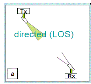
| Directed LOS is used for point-to-point communication links, mainly, in outdoor and in some cases in indoor environment too as shown in Fig.1 It exhibits low power requirements as well as creates a high-power flux density at the photo detector as the optical is concentrated in a very narrow beam. The LOS link further offers the highest data rate (hundreds of Mbps and above) over a link span from a few meters to 5 km. Moreover, directed LOS links do not suffer from multipath-induced signal distortion. When used with a narrow field-of-view (FOV) receiver, the noise from the ambient light sources is also largely rejected [10]. The data rate is, therefore, limited by free-space path loss rather than the effects of multipath dispersion [10], [11]. There are some disadvantages too. For indoor applications, providing coverage area and roaming could become problematic, if the coverage area provided by a signal channel is very small. Mobile users cannot be supported by directed LOS links because there is a requirement for alignment of receiver and transmitter modules. In LOS OWC-based LANs catering for single users, the transmitter/receiver base station is usually mounted to the room ceiling. However, a cellular topology is adopted in situations where there is a need to offer services to multiple users within a relatively large room. In cellular topology, the narrow transmit optical beam is replaced with a source of a wide optical foot print. In cellular OWC links, the communication between mobile users is established via a base station located at the centre of each cell and the optical signal is broadcast to all mobile users within the cell. Cellular OWC topology requires no alignment and tracking and offers reduced power efficiency as well as mobility. As a high proportion of the transmitted light is detected at the photo detector from a number of different directions, they overcome blocking problem by relying on reflections from surfaces of objects within rooms. However, they must contend with multipath-induced dispersion and incur a high optical path loss (thus higher transmit power. While multipath propagation does not result in multipath fading in indoor IR systems, since detector sizes are huge in comparison with the wavelength, it does give rise to inter- symbol interference (ISI), thus limiting the data rate to around a few Mbps in a typical size room. In addition to this, OWC degrades the link performance as it is able to operate in environments with intense ambient light levels. |
NON-DIRECTED LOS
|
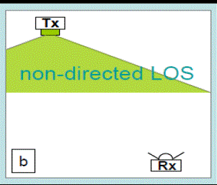
| Non-directed links are suitable for point to multipoint broadcast applications as shown in Fig.2 They require no alignment and tracking but offer robustness to shadowing and blockage [12]. A high proportion of the transmitted light is detected at the photo detector from a number of different directions and this helps in minimizing the blocking problem. They have higher transmitting power but acquire a higher optical path loss. They must also contend with multipathinduced dispersion It limits the data rate to around a few Mbps in a typical size room and give rise to Inter-Symbol Interference (ISI) as sizes are huge in comparison with the wavelength In addition to this, OWC links ought to be able to operate in environments with intense ambient light levels, thus degrading the link performance. |
DIFFUSE CONFIGURATION
|
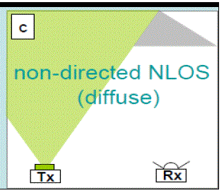
| The configuration is also known as non-directed non- LOS [11] as shown in Fig.3 It typically consists of a transmitter pointing directly towards the ceiling, emitting a wide IR beam. The diffuse OWC indoor topology is the most suitable for infrastructure and LAN adhoc networks [11], [13] as it is almost resistant to blockage of the transmission path. It d o e s n o t require an LOS path to be maintained nor does it require careful alignment of the transmitter and receiver modules. It is also extremely flexible. Unfortunately, for a horizontal separation of 5 m, a high path loss, typically 50– 70 dB is experienced [14]. The path loss is increased further, if the main signal path is blocked by a temporary obstruction, such as a person, obscures the receiver, a situation referred to shadowing [15]. In addition, a photo detector with a wide FOV normally collects signals that have under-gone one or more reflections from ceiling, walls and room objects. An array of photo detector can further be improved and reflections can be attenuated when the signal with reflection coefficients between 0.4 and 0. 9 are replaced by the non imaging receiver in both non directed and non-LOS links by a single imaging light concentrator. For example, the power requirements of pulse-position modulation (PPM) are higher than the On-Off Keying (OOK) at higher data rates. However, the eye safety regulations and electrical power consumption in portable (battery-powered) devices limits the average optical power emitted by an IR transceiver. Therefore, the use of power-efficient modulation techniques is desirable. In addition, in diffuse systems, the entire room needs to be illuminated by a single or multiple transmitters. This can be achieved by diffused light propagation after a few reflections but it requires a relatively huge transmitted optical power. For instance, 475 of transmit power for a diffuse 50- Mbps link at a horizontal link separation of 5m between transmitter and for receiver both directed to the ceiling [16]. It improves the link performance by the way of reducing the multipath distortion and the ambient light noise. Use of multi beam transmitter and a multiple element narrow FOV angle-diversity receiver improves the performance of diffuse systems. The light power is projected on to a ceiling, over a regular grid of small spots, in the form of multiple narrow beams of equal optical intensity. In this configuration, each diffusing spot offers reduced path loss leading to the increased link Signal-to-Noise Ratio (SNR) by ~20 dB, and so would be considered as a source offering a LOS link to a narrow FOV receiver[14], [15]. Due to imaging concentrators and physical orientation, the angle-diversity receivers consists of multiple receiver elements effectively pointing in different directions [14]. The photocurrent generated by each receiver element can be processed in a number of ways, including the use of digital wavelet- AI techniques. The ambient noise and multipath distortion can be reduced by this type of receiver as these unwanted contributions are usually received from different directions to that of the desired signal [12]. The performance of such schemes has been analyzed in Refs. [16], [18]. The Inter Symbol Interference can be control led by using Dielectric Totally Internally Reflecting Concentrator (DTRIC) optical antenna. LOS links can be used for a number of outdoor applications such as university campuses, last miles access networks, cellular communication backhaul, inter satellite communications, satellite uplink/downlink, deep space probes to ground, disaster recovery, fibre communication back-up, video etc…. |
HYBRID LOS SYSTEMS
|
| In hybrid LOS systems, all the elements have a narrow FOV. Only the transmitter or the receiver has a wide FOV. In typical hybrid LOS system, the transmitters are mounted on the ceiling to illuminate a wide area. For the directed non-LOS links, the transmitter has a narrow angle emission and the receiver has a narrow FOV. For overcoming any obstacles between them and enabling the first reflection to reach the receiver, the transmitter is aimed at a reflective surface. In addition to this, the multipath dispersion is minimized by r eceiving the information signal after a single reflection [15]. However, due to a highly directional transmitter and receiver, the alignment is problematic. Either a wide beam transmitter or a narrow FOV receiver or vice versa, is incorporated in the hybrid system. This relaxes the need for strict alignment between the transmitter and the receiver. The system is affected by multipath propagation though blocking probability can be significantly reduced using the link design. |
THEORETICAL APPROACH
|
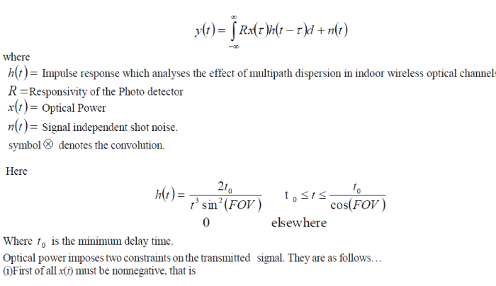
| Directed line of sight and the multispot diffuse (quasi-diffuse) configuration links can be increased by reducing the Field of View (FOV), which is proved by a Mathematical equation. Indoor OWC link is evident itself as the Inter- Symbol Interference (ISI) as they do not suffer from the effects of multipath fading but suffer from the effects of dispersion. Dispersion is modeled as a linear base-band channel impulse response h(t). For a given position of transmitter, receiver and intervening reflecting objects, the channel characteristic of an OWC link is fixed. The channel characteristic only changes when these components are moved by distances of the order of centimetres [19]. The channel may be considered as quasi-static because they vary only on the time scale of many bit periods due to the relatively slow movement of objects, and people within a room and due to high bit rates [20]. |
| The Intensity Modulation with Direct Detection (IM/DD) of an optical wireless link summarized by the following equations |
 |
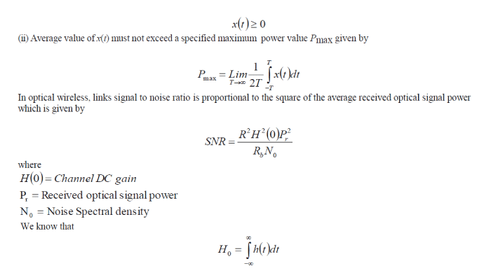 |
| In an optical system, only a limited path loss can be bearable and requires relatively high optical transmit powers. It is suggested that modulation techniques that possess a high peak-to- mean power ratio are most approvable because of the fact that the average optical transmit power is limited. This is generally achieved by balancing the power efficiency against the bandwidth efficiency. When shot noise is dominant, the SNR is also proportional to the photo detector area because the received electrical power and the variance of the shot noise are proportional to 2 d A and d A , respectively, where d A is the receiver detector area. Thus, the use of large-area detectors is favourable for single element receivers. However, there is a limiting effect on receiver bandwidth and the transmission capacity as the detector area and its capacitance increase. This is in direct conflict with the increased bandwidth requirement associated with power efficient modulation techniques, and hence, a trade-off exists between these two factors. Transfer function of an optical wireless channel How( f) is defined by |
 |
SIMULATION RESULTS
|
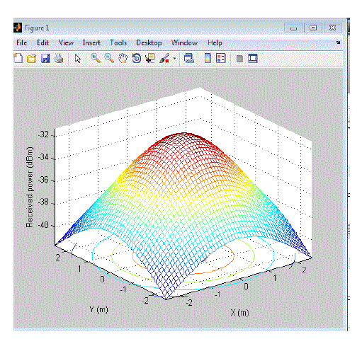
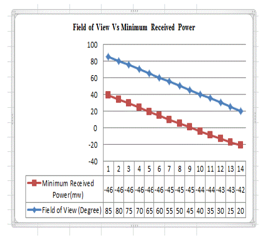
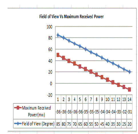
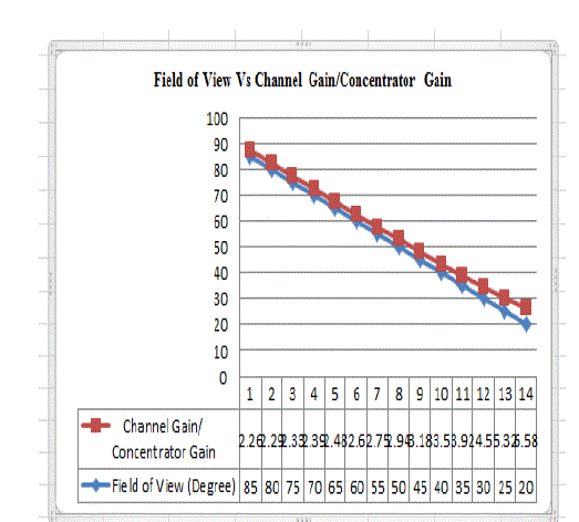
| Simulation studies involves enhancement of power ratio of an Optical Wireless Channel using Matlab by enhancing the Directed Line of Sight Channel Gain by reducing the receiver Field of View (FOV). The Field of View of the receiver is related to the collection area of a lens and the photo detector area. In Fig. 1. Directed line of Sight is shown. Authors have used Directed LOS for point-to-point communication links in indoor environment. In Fig. 2. Non-directed LOS is shown that are suitable for point to multipoint broadcast applications. In Fig. 3. Non-directed non-LOS is shown that d o e s n o t require an LOS path to be maintained nor does it require careful alignment of the transmitter and receiver modules. Table 1 shows the values of maximum received power, minimum received power and the Concentrator/Channel Gain at different field of View. As shown in table, the maximum and minimum received power and Channel gain increases on decreasing the Field of view. Fig. 4 shows the 3-D view of Line of Sight Channel gain drawn using Matlab. In Fig. 5, a graph is drawn between minimum received power and the Field of View and in Fig. 6 a graph is drawn between Maximum received power and the angles of Field of view. As shown, the Field of View is inversely proportional to both minimum and maximum received power. In Fig. 7, the graph drawn between the angles of Field of View and the Concentrator/ Channel Gain. |
CONCLUSION
|
| Based on the simulation result in this article following point wise conclusions can be drawn |
| (i)The Directed line of sight and the multispot diffuse (quasi-diffuse) configuration links can be increased by reducing the Field of View (FOV). |
| (ii)The Field of View (FOV) of the receiver is somehow proportional to the collection area of a lens and the photo detector area. |
| (iii)The concentrator gain or channel gain is inversely proportional to the value of FOV, which is proved by simulated results. |
Tables at a glance
|
 |
| Table 1 |
|
| |
Figures at a glance
|
 |
 |
 |
 |
| Figure 1 |
Figure 2 |
Figure 3 |
Figure 4 |
 |
 |
 |
| Figure 5 |
Figure 6 |
Figure 7 |
|
| |
References
|
- WasineeNoonpakdee, Jiang LIU, Shigeru Shimamoto, ?Position based Access Scheme for Indoor Optical wireless Communication Systems?, 8th Annual IEEE consumer communication and Networking Conference-Wireless Consumer Communications and networking, pp958- 962,2011.
- Jiang LIU, ,WasineeNoonpakdee, ?Evalution of Reflected Light Effect for Indoor Wireless Optical CDMA System?, IEEE WCNC
- PHY,pp1688-1692,2011.
- Mahdy A. and Deogun J.S, ?Wireless optical communications: a survey? IEEE WCNC, Vol.4, pp2399- 2404,March 2004.
- K.Sasaki, N. Minato. T. Ushikubo and Y. Arimoto, First OCDMA experiment demonstration over free space and optical fiber link,?OFC/NFOEC 2008. San Diego, califonia, MR8?Febuary- 2008.
- R.You and J .M. Kahn, ?Upper-bounding the capacity of optical IM/DD channels with multiple – subcarrier modulation and fixed bias using trigonometric moment space method,? IEEE Transactions on information Theory, vol.48, no. 2, pp. 514-523, February 2002.
- Damon W.K. Wong, George C.K. Chen and Jianping Yao, ?Optimization of Spot pattern in indoor diffuse optical wireless local area networks,? Optics Express 3000,Vol.13,April 2005.
- S. Kirkpatrick,C.D. Jr. Gerlatt, and M.P. Vecchi, ?Optimization by Stimulated Annealing,? Science 220,p.p671-680, 1983.
- J. P. Yao, G. Chen, and T. K. Lim, "Holographic diffuser for diffuse infrared wireless home networking," Optical Engineering, vol. 42, no. 2, pp. 317-324, February 2003.
- Tim C.W. Schenk. Lorenzo Feri. Hongming Yang. Jean-Paul M.G. Linnartz.?Optical Wireless CDMA Employing Solid State Lighting LEDs ?IEEE Photonics Society Summer Topicals 2009,pp-23- 24,July 2009.
- O. Bouchet, H. Sizun, C. Boisrobert, F. De Fornel and P. Favennec, Free-Space Optics:Propagation and Communication, London: ISTE Ltd, 2006.
- S. Rajbhandari, Wavelet— Artificial Neural Network Receiver for Indoor Optical Wireless Communications.Journal of LightwaveTechnology, 29 (17). pp. 2651-2659. ISSN 0733-8724.
- A. M. Street, P. N. Stavrinou, D. C. Obrien and D. J. Edwards, Indoor optical wireless systems—A review, Optical and Quantum Electronics, 29, p.p.349–378, 1997.
- O. Bouchet, M. El Tabach, M. Wolf, D. C. O’Brien, G. E. Faulkner, J. W. Walewski, S. Randel, M Franke, S. Nerreter, K. D. Langer, J. Grubor and T. Kamalakis, Hybrid wireless optics (HWO): Building the next-generation home network,Communication Systems, Networks and Digital Signal Processing, 2008. CNSDSP 2008. 6th International Symposium on,Graz, Austria, pp.283–287. 2008,
- A. Sivabalan and J. John, Improved power distribution in diffuse indoor optical wireless systems employing multiple transmitter configurations, Optical and Quantum Electronics,38, p.p.711–725, 2006.
- J. M. Kahn, P. Djahani, A. G. Weisbin, K. T. Beh, A. P. Tang and R. You, Imaging diver- sity receivers for high-speed infrared wireless communication, IEEE Communications Magazine, 36,p.p 88–94, 1998.
- W. Kang and S. Hranilovic, ?Power reduction techniques for multiple-subcarrier modulated diffuse wireless optical channels,?IEEE Transactions on Communication, vol. 56, no. 2, pp 279-288, February 2008
- M. A. Naboulsi, H. Sizun and F. d. Fornel Wavelength selection for the free space optical telecommunication technology, SPIE, 5465, p.p. 168–179, 2004.
- GiulioCossu, RaffaeleCorsini, and Ernesto Ciaramella, ?High-Speed Bi-directional Optical Wireless System in Non-Directed lineof- Sight Configuration?, Journal Of Lightwave Technology, Vol. 32, No. 10, May 15, 2014
- R. Ramirez-Iniguez and R. J. Green, Optical antenna design for indoor optical wireless communication systems, International Journal of Communication Systems—Special Issue on Indoor Optical Wireless Communication Systems and Networks, 18,p.p 229–245, 2005.
- Z. Ghassemlooy, W.Popoola, S. Rajbhandari- Optical Wireless Communications System and Channel Modelling with MATLAB.
|