In this paper a design of proximity coupled equilateral triangular microstrip antenna with diamond shape slot on the radiating patch is studied. The antenna consists of two layers with glass epoxy material of thickness (h) 0.32cm each forming total thickness of 0.64cm. The proposed diamond shape slot loaded antenna resonates at two different frequencies 2.95GHz and 5.91GHz with bandwidth of 8.87% and 11.05% respectively with compared to that of conventional microstrip antenna which resonates at 3.07GHz with bandwidth of 9.15%. These antennas are simulated by using Ansoft HFSS electromagnetic simulation software. The antenna parameters such as return loss, bandwidth and radiation pattern are discussed and presented.
Keywords |
| Proximity coupled, triangular microstrip antenna, diamond shape, bandwidth, radiation pattern |
INTRODUCTION |
| Due to the many attractive features and desirable characteristics, the microstrip antennas have gained the most
important candidate for the modern wireless communication systems as well as an ultimate solution for development of
handheld mobile devices in both commercial industries and research academia [1]. The present era of wireless
communication possess many desirable features such as light weight, wide bandwidth, low cost, direct integrability
with microwave circuitry [2]. To meet these requirements, microstrip antenna is an essential element which offers an
optimal solution for modern wireless communication. Among different shapes of radiating patches such as square,
rectangular, circular, ellipse etc. the equilateral triangular radiating patch was found to exhibit good radiation
characteristics, simple to design and compact in size when compared to other microstrip patch shapes [3]. |
| In recent years, the microstrip antenna designers have proposed many techniques to improve the antenna parameters
such as microstripline feeding approaches of aperture coupled feeding and proximity coupled feeding etc. To improve
the impedance bandwidth, radiation characteristics, gain, multiband operation etc., slot loading techniques [4-7]. In [4],
the 50Ω microstripline inset fed triangular microstrip antenna has been studied with reconfiguration of a chip resistor.
The dual frequency equilateral triangular microstrip is etched on the FR4 dielectric substrate is proposed in [5], the
proposed antenna also is designed for different substrate thicknesses and patch sizes to achieve the dual polarization. A
double T shaped stub tuning triangular microstrip antenna with slot [6] has been studied for wideband operation. A
small slot coupled with a shorting-pin or chip-resistor triangular patch antenna has been presented in [7] for broadband
operation. This antenna also resonates at fixed operating frequency with size reduction characteristics. Moreover, the
above methods are complicated. To overcome these difficulties, in this paper simple microstripline proximity coupled
feeding technique is used to achieve the dual band operation with wide impedance bandwidth. |
ANTENNA DESIGN CONSIDERATION |
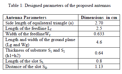
| The proposed antenna is designed for the frequency of 3 GHz using the relations present in the literature for the design
of equilateral triangular microstrip antenna. A low cost glass epoxy substrate material with substrate S1and S2 having
thicknesses of 0.32 cm and with dielectric constant εr = 4.2 is used to simulate the antenna. |
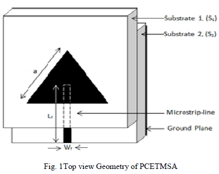
| Fig. 1 shows the geometry of proximity-coupled equilateral triangular microstrip antenna (PCETMSA).The equilateral
triangular radiating patch with length ‘a’ is etched on top surface of substrate S1. The value of ‘a’ is obtained from the
equation (1); |
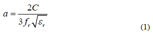 |
| where, C is the velocity of light and fr is the resonating frequency. The microstripline feed of length Lf and width Wf is
etched on the top surface of substrate S2. The substrate S2 is placed below substrate S1 such that the tip of the feedline
and the centre of the radiating patch coincide one over the other. The bottom surface of the substrate S2 acts as the
ground plane. The dimensions of the ground plane Lg and Wg are calculated from equation; |
| Wg = Lg = 6h+a |
 |
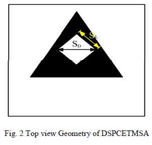
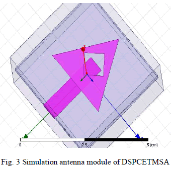
| Further, the study is carried out by loading diamond shape slot on the radiating patch as shown in Fig. 2 and Ansoft
HFSS antenna module of DSPCETMSA is as shown in Fig. 3, where SD is the distance of the diamond shape slot and
SL is the side length of the slot. All the dimensions of the PCETMSA and DSPCETMSA are shown in Table 1. |
 |
 |
 |
SIMULATION RESULTS AND DISCUSSIONS |
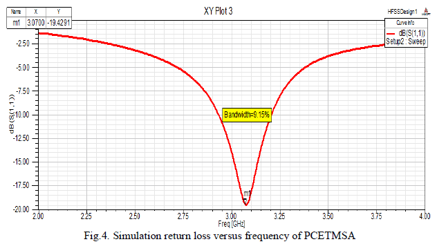
| The proposed antennas are designed and simulated using Ansoft HFSS simulation software. The impedance bandwidth
over return loss less than -10dB is calculated. The variations of return loss versus frequency of PCETMSA and
DSPCETMSA are shown in Fig. 4 and 5. From these figures, the impedance bandwidth is calculated using the
equation (2), |
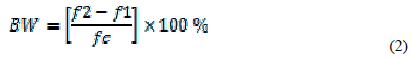 |
| where, f1and f2 are the lower and upper cut-off frequencies of the operating bands respectively when its return loss
reaches –10dB and fC is the center frequency between f1and f2. |
 |
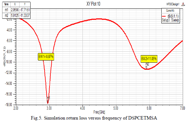 |
| From the Fig. 4 and 5 it is observed that, the PCETMSA resonates at 3.07 GHz with impedance bandwidth of 9.15%
and the minimum return loss is found to be -19.42dB, whereas after loading the diamond shape slot in the radiating
patch by keeping all the parameters constant, the antenna resonates at two different frequency i.e., 2.95GHz and
5.91GHz with impedance bandwidth 8.87% and 11.05%, which is 1.90 times more when compared to the conventional
microstrip antenna and the minimum return loss measured is found to be -17.71dB and -11.33dB respectively as shown
in Fig. 5. |
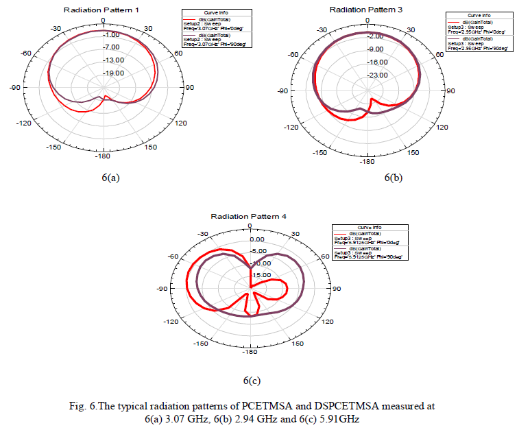
| The E and H plane radiation patterns of the proposed antennas for φ at 00 and 900and ϴ at 00 and 900is as shown in
Fig. 6(a), Fig. 6(b) and Fig. 6(c). From these figures it is clear that, the obtained radiation patterns are broadside in
nature. |
 |
CONCLUSIONS |
| From the detailed study, it is clear that the PCETMSA antenna gives a single frequency band but after loading the
diamond shape slot i.e. DSPCETMSA resonates for two operating frequency bands with enhancement in the bandwidth
with better broadside radiation pattern at the resonating frequencies. The antenna is also superior as it uses low cost
substrate material and finds applications in modern communication systems such as WLAN, Bluetooth and Wi-Fi. |
References |
- Constantine. A. Balanis “Antenna theory analysis and design”, John Willey, New York, 1997.
- D.M.Pozar, “Microstrip Antennas,” Proceeding, IEEE, Vol. 80, pp.79- 81, January,1992.
- R. Garg, P. Bartia, I. Bhal, and A. Ittipiboon, “Microstrip antenna design handbook”, Artech House, Norwood, MAY, 2001.
- Y. F. Lin and K. L. Wong, “Compact broadband triangular microstrip antennas with an inset microstrip-line feed,” Microwave Opt. Technol.Lett., Vol. 17, pp. 169–170, Feb. 20, 1998.
- J.-S. Row and K.-W .Lin, “Low-profile design of dual-frequency and dual-polarised triangular microstrip antennas,” Electron.Lett., Vol. 40,No. 3, 2004.
- J.-Z. Zuercher, O. Staub, and K. Skrivervik, “Triangular slot antenna with a double-T-shaped tuning stub for wideband operation, “MicrowaveOpt. Technol. Lett., Vol. 49, No. 9, pp. 2123-2128, Sep. 2007.
- J. H. Lu, C. L. Tang, and K. L. Wong, “Slot-coupled small triangular microstrip antenna,” Microwave Opt. Technol. Lett., Vol. 16, pp. 371–374, Dec. 20, 1997.
|