ISSN ONLINE(2278-8875) PRINT (2320-3765)
ISSN ONLINE(2278-8875) PRINT (2320-3765)
Chandan Kumar Tiwary1, Dr. Amita Mohar2
|
| Related article at Pubmed, Scholar Google |
Visit for more related articles at International Journal of Advanced Research in Electrical, Electronics and Instrumentation Engineering
This paper shows the work done on the method to operate a grid connected hybrid system which is composed of a Photovoltaic (PV) array and a Proton exchange membrane fuel cell .With the proton exchange membrane the hybrid system output power becomes controllable. Here the system uses two operation modes, the unitpower control (UPC) mode and the feeder-flow control (FFC) mode. This papers discusses the coordination of two control modes, the coordination of the PV array and the proton exchange membrane fuel cell in hybrid system and the way in which the reference parameters are determined. The proposed operating strategy with a flexible operation mode change always operates the The PV array operates at maximum output power and the Proton Exchange membrane cell in its high efficiency performance band, using the proposed strategy which has a flexible operation mode thus improving the performance of system operation with enhance stability and reduction in number of operating mode change.
Keywords |
| Distributed generation, fuel cell, hybrid system, microgrid, photovoltaic, power management |
INTRODUCTION |
| With the world economic development and growing demand for energy, the conventional energy sources have become increasingly unable to meet the world demand for the energy. Thus, it is important to explore more and better means of alternative energy sources like sunlight, wind and biomass. Photovoltaic energy is a source of interesting energy; it is renewable, inexhaustible and non-polluting, and it is more and more intensively used as energy sources in various applications [1]. In regard to endless importance of solar energy, it is worth saying that solar energy is a unique perspective solution for energy crisis. Meanwhile, despite all these advantages of solar energy, they do not present desirable efficiency [2], [3]. The main renewable sources are biomass, geothermal, hydro, photovoltaic, and wind. Photovoltaic (PV) power is expected to have the fastest annual growth rate having already shown a top growth rate of more than 50% in 2006 and 2007 [4]. PV power systems have the advantage that their installation is static (i.e. no moving parts), simple and quickly compared to other renewable sources. Thus, they have a longer lifetime span, (typically more than 20 years) [5]. Moreover, due to their low operational cost and maintenance, they provide a significant solution for powering remote areas. The photovoltaic (PV) used to harness the solar energy tends to become an uncontrollable source because of the use of maximum power point tracking (MPPT) technique to continuously deliver the highest power to the load when variations in irradiation and temperature occur. The disadvantage of PV energy is that the PV output power depends on weather conditions and cell temperature, making it an uncontrollable source. Furthermore, it is not available during the night. In order to overcome these inherent drawbacks, alternative sources, such as PEMFC, should be installed in the hybrid system. By changing the FC output power, the hybrid source output becomes controllable. However, PEMFC, in its turn, works only at a high efficiency within a specific power range. |
| The hybrid system can either be connected to the main grid or work autonomously with respect to the grid connected mode or islanded mode, respectively. In the grid-connected mode, the hybrid source is connected to the main grid at the point of common coupling (PCC) to deliver power to the load. When load demand changes, the power supplied by the main grid and hybrid system must be properly changed. The power delivered from the main grid and PV array as well as PEMFC must be coordinated to meet load demand. The hybrid source has two control modes: 1) unit-power control (UPC) mode and feeder-flow control (FFC) mode. In the UPC mode, variations of load demand are compensated by the main grid because the hybrid source output is regulated to reference power. Therefore, the reference value of the hybrid source output must be determined. In the FFC mode, the feeder flow is regulated to a constant, the extra load demand is picked up by the hybrid source, and, hence, the feeder reference power must be known. |
| The proposed operating strategy is to coordinate the two control modes and determine the reference values of the UPC mode and FFC mode so that all constraints are satisfied. This operating strategy will minimize the number of operating mode changes, improve performance of the system operation, and enhance system stability. |
SCHEME DETAILS |
Structure of Grid-Connected Hybrid Power System |
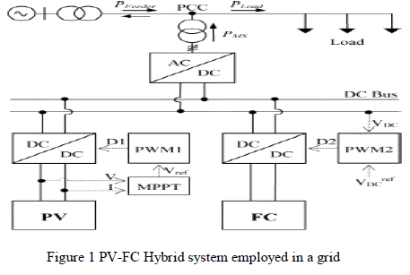
| The system consists of a PV-FC hybrid source with the main grid connecting to loads at the PCC as shown in Fig. 1. The photovoltaic [8], [9] and the PEMFC [10], [11] are modeled as nonlinear voltage sources. These sources are connected to dc–dc converters which are coupled at the dc side of a dc/ac inverter. The dc/dc connected to the PV array works as an MPPT controller. Many MPPT algorithms have been proposed in the literature, such as incremental conductance (INC), constant voltage (CV), and perturbation and observation (P&O). |
| The P&O method has been widely used because of its simple feedback structure and fewer measured parameters [12]. The P&O algorithm with power feedback control [13]–[15] is shown in Fig. 2. As PV voltage and current are determined, the power is calculated. At the maximum power point, the derivative dP/dV is equal to zero. The maximum power point can be achieved by changing the reference voltage by the amount of ΔVref. |
Photovoltic Array Model |
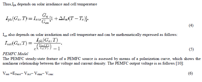
| The mathematical model 3 and 4 can be expressed as |
 |
 |
 |
 |
| where ENerst is the “thermodynamic potential” of Nerst, which represents the reversible (or open-circuit) voltage of the fuel cell. Activation voltage drop VAct is given in the Tafel equation as |
 |
MPPT Control |
| Many MPPT algorithms have been proposed in the literature, such as incremental conductance (INC), constant voltage (CV), and perturbation and observation (P&O). The two algorithms often used to achieve maximum power point tracking are the P&O and INC methods. The INC method offers good performance under rapidly changing atmospheric conditions. However, four sensors are required to perform the computations. |
| If the sensors require more conversion time, then the MPPT process will take longer to track the maximum power point. During tracking time, the PV output is less than its maximum power. This means that the longer the conversion time is, the larger amount of power loss [12] will be. On the contrary, if the execution speed of the P&O method increases, then the system loss will decrease. Moreover, this method only requires two sensors, which results in a reduction of hardware requirements and cost. Therefore, the P&O method is used to control the MPPT process. |
| In order to achieve maximum power, two different applied control methods that are often chosen are voltage-feedback control and power-feedback control [13], [14]. Voltage-feedback control uses the solar-array terminal voltage to control and keep the array operating near its maximum power point by regulating the array’s voltage and matching the voltage of the array to a desired voltage. The drawback of the voltage-feedback control is its neglect of the effect of irradiation and cell temperature. Therefore, the power-feedback control is used to achieve maximum power. |
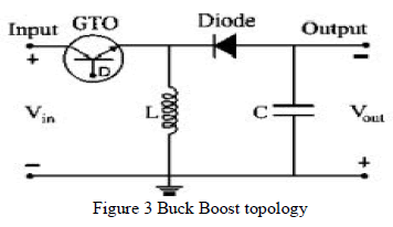
| The P&O MPPT algorithm with a power-feedback control [14], [15] is shown in Fig. 2. As PV voltage and current are determined, the power is calculated. At the maximum power point, the derivative (dP/dV ) is equal to zero. The maximum power point can be achieved by changing the reference voltage by the amount of ïÃÂÃâVref. . In order to implement the MPPT algorithm, a buck-boost dc/dc converter is used as depicted in Fig. 3. The parameters L and C in the buck-boost converter must satisfy the following conditions [16]: |
 |
| The buck-boost converter consists of one switching device (GTO) that enables it to turn on and off depending on the applied gate signal D. The gate signal for the GTO can be obtained by comparing the sawtooth waveform with the control voltage [12]. The change of the reference voltage ΔVref obtained by MPPT algorithm becomes the input of the pulsewidth modulation (PWM). The PWM generates a gate signal to control the buck-boost converter and, thus, maximum power is tracked and delivered to the ac side via a dc/ac inverter. |
CONTROL OF THE HYBRID SYSTEM |
| Unit power control, feeder flow control, and mixed control mode are the control modes used in microgrid. In the UPC mode, the DGs (the hybrid source in this system) regulate the voltage magnitude at the connection point and the power that source is injecting. In this mode if a load increases anywhere in the microgrid, the extra power comes from the grid, since the hybrid source regulates to a constant power. In the FFC mode, the DGs regulate the voltage magnitude at the connection point and the power that is flowing in the feeder at connection point Pfeeder . With this control mode, extra load demands are picked up by the DGs, which maintain a constant load from the utility viewpoint. |
| In this paper, a coordination of the UPC mode and the FFC mode was investigated to determine when each of the two control modes was applied and to determine a reference value for each mode. With both the sources having their constraints the reference power must be set at an appropriate value so that the constraints of these sources are satisfied. |
OPERATING STRATEGY OF THE HYBRID SYSTEM |
| As mentioned before, the purpose of the operating algorithm is to determine the control mode of the hybrid source and the reference value for each control mode so that the PV is able to work at maximum output power and the constraints are fulfilled. Once the constraints (PLow FC , Pup FC , Pmax F , ) are known, the control mode of the hybrid source (UPCmode and FFC mode) depends on load variations and the PV output. In the UPC mode, the reference output power of the hybrid source PRef MS depends on the PV output and the constraints of the FC output. |
RESULT AND DISCUSSION |
Simulation results without Hysteresis |
 |
 |
 |
 |
| Output With Hysteresis |
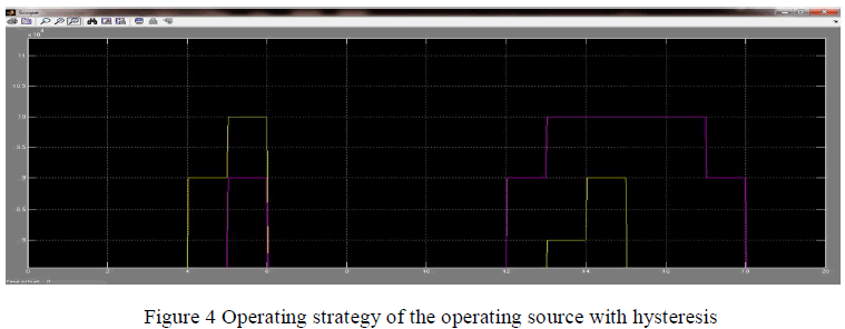 |
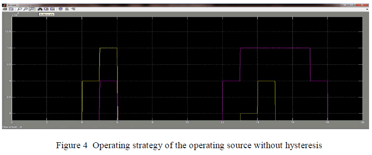
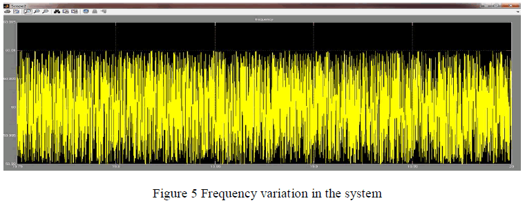
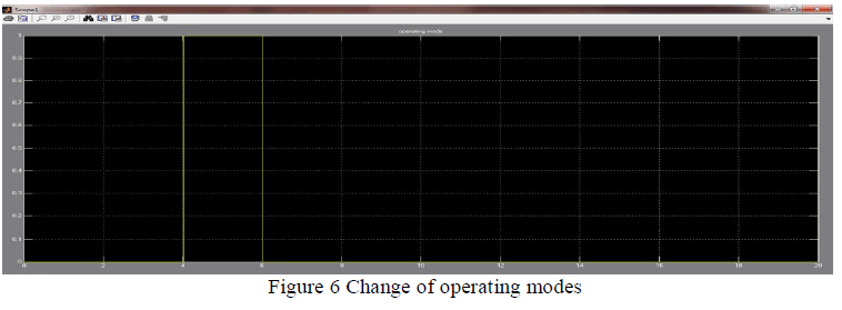
| We observe that between t=13 sec to t = 17 sec the output shows glitches when we are using the system without hysteresis but when we are using hysteresis we are able to reduce the glitches between t=13 sec to t = 17 sec. We can also make the conclusion that the system frequency remains well within the specified range |
CONCLUSION |
| In this paper we have been able to present an available method to operate a hybrid grid-connected system which is composed of a PV array and PEMFC with hysteresis and witout hysteresis. The operating strategy of the system is based on the UPC mode and FFC mode. The purpose for going for this particular strategy is to determine the control mode, to minimize the number of mode changes, to operate PV at the maximum power point, and to operate the FC output in its high-efficiency performance band. |
| In brief, the proposed algorithm presents a simplified and flexible method to operate a hybrid source in a gridconnected microgrid which can improve the performance of the system’s operation and thus allows the system to work more stably while maximizing the PV output power. |
| Future work may involve considering the operation of the battery into account to enhance operation performance of the system. Work may also be carried to study the application of the operating algorithm to a microgrid with multiple feeders and DGs will also be studied in detail. |
References |
|