International Journal of Advanced Research in Electrical, Electronics and Instrumentation Engineering
ISSN ONLINE(2278-8875) PRINT (2320-3765)
ISSN ONLINE(2278-8875) PRINT (2320-3765)
H.Bala Murugan1, S.V.Siva Nagaraju2, K. Satish Kumar3, KC Ramakrishnan4 and VE Sowjanya5
|
| Related article at Pubmed, Scholar Google |
Visit for more related articles at International Journal of Advanced Research in Electrical, Electronics and Instrumentation Engineering
The future of energy in the world today is focusing more and more on alternative energy sources to remove the strain of fossil fuels which are becoming more and more costly.A naturally replenished energy known as renewable energy is promising to become the future energy source around the world.One of the most fascinating aspects of solar cells is their ability to convert the most abundant and free forms of energy into electricity without moving parts or components. Also, they do not produce any adverse forms of pollution that affect the ecosystem.An important part of the project is dedicated to current measurement and data acquisition systems dedicated for monitoring PV systems. Applied solutions and experimental results are discussed in terms of accuracy and optimization needs of the operation.
Keywords |
| Solar cell , DAQ, Photo voltaic cell, Current,Voltage |
INTRODUCTION |
| Residential owners to large corporations are seeking methods of producing their own electricity, the main source being solar energy. Data acquisition systems (DAQ) can measure and store data collected from hundreds of channels simultaneously. The majority of systems contain from eight to 32 channels, typically in multiples of eight. An ideal data acquisition system uses a single ADC for each measurement channel. In this way, all data are captured in parallel and events in each channel can be compared in real time. But using a multiplexer that switches among the inputs of multiple channels and drives a single ADC can substantially reduce the cost of asystem.NI has found that there was no monitoring solution taking a wide range of variables into consideration. It also found that the market required a solution that did not need an expensive solar simulator and was capable of measuring PV module performance changes with time. In responding to the market demand, NI has developed an efficiency monitoring solution for PV modules/cells that is cost effective and can help cell/module manufacturers perform tests with greater accuracy and increased throughput. Essentially this solution involves the integration of a Personal Computer (PC), Data Acquisition (DAQ), a battery array and a Solar Array Simulator (SAS) to create a stand-alone PV system and to test and simulate the system. The information obtained by monitoring parameters, such as average battery’s temperature, voltage and current, is fed to the PC via the DAQ for analysis. This customized control interface has been developed by utilizing LabVIEW software. |
B. Why Solar Cells Are Known As Photovoltaic, Or PV Cells : |
| The word photovoltaic is made up of pieces, with photo- indicating light, and voltaic implying that a potential difference (measured in volts) is set up by the action of the light. The light directly liberates electrons, and the diode action insures that the current of electrons flows only one way. (Alternatively, the incoming light could liberate vacancies, or lacks of electrons at a site, which are known as holes).That is, if one of the materials making up the junction exhibits the photoelectric effect and produces charges, they can flow in only one direction. The current is forced to flow through an external circuit in order to get to the other side of the junction and combine with the opposite sign charge. So, as long as light is incident on the solar cell, charges will be produced by the photoelectric effect and the current will flow. When there is no light, there is not a current. This is the problem; if the Sun goes down, or if a dark cloud appears, the cell stops producing current. While wind electricity is also intermittent, it is not diurnally intermittent, that an interconnections of wind machines in different areas even out the energy supply. |
C. SOLAR CELLS: |
| Solar cells work to make light into electricity directly. When light shines, electrons are liberated in the ptype region and holes produced in the n-type region; this lowers the potential energy barrier at the junction. A current flows and establishes an external potential difference. Solar cells act in a way similar to the diode, so that current can flow in only one direction when the cell is exposed to light. Even though Becquerel discovered the effect in 1839, the first solar cell was made only in 1954. |
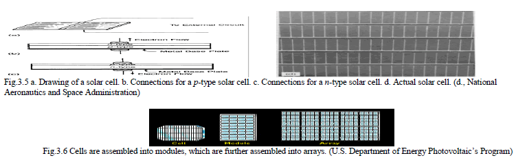 |
| The cells are single wafers of semiconductor. Each wafer can put out a small amount of power at the potential difference (voltage) determined by its band gap physics. To use the cells, they must be assembled into larger structures and then into even larger structures. |
SOFTWARE REQUIREMENTS AND ITS SPECIFICATIONS |
A. LabVIEW: |
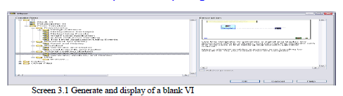
| LabVIEW provides built-in template VIs that include the subVIs, functions, structures, and front panel objects you need to get started building common measurement applications. Complete the following steps to create a VI that generates a signal and displays it in the front panel window. |
| 1. Launch LabVIEW. |
| 2. In the Getting Started window, click the New or VI from Template link to display the New dialog box. |
| 3. From the Create New list, select VI»From Template»Tutorial (Getting Started)»Generate and Display. This template VI generates and displays a signal. |
| 4. Click the OK button to create a VI from the template. You also can double-click the name of the template VI in the Create New list to create a VI from a template. LabVIEW displays two windows: the front panel window and the block diagram window. |
| A preview and a brief description of the template VI appear in the Description section. Figure below shows the new dialog box and the preview of the Generate and Display template VI. |
 |
| 5. Examine the front panel window. The user interface, or front panel, appears with a gray background and includes controls and indicators. The title bar of the front panel indicates that this window is the front panel for the Generate and Display VI. |
| 6. Select Window»Show Block Diagram and examine the block diagram of the VI. The block diagram appears with a white background and includes Vis and structures that control the front panel objects. The title bar of the block diagram indicates that this window is the block diagram for the Generate and Display VI. |
 |
C. Configuring a VI to Run Continuously until the User Stops It: |
| In the current state, the VI runs once, generates one signal, and then stops running. To run the VI until a condition occurs, you can use a While Loop. |
| Complete the following steps to add a While Loop to the block diagram. |
| 1. Display the front panel and run the VI. The VI runs once and then stops. The front panel does not have a stop button. |
| 2. Display the block diagram. |
| 3. Click the Search button, shown at left, on the Functions palette, and enter while in the text box. LabVIEW searches as you type the first few letters and display any matches in the search results text box. If there are objects with the same name, use the information in the brackets to the right of each object name to decide which object to select. Some objects are located on multiple palettes because you can use them for multiple applications. |
| 4. Double-click While Loop <<Execution Control>> to display the Execution Control subpalette and temporarily highlight the While Loop on the subpalette. |
| 5. Select the While Loop on the Execution Control palette. |
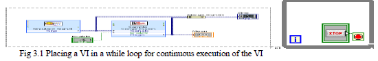
| 6. Move the cursor to the upper left corner of the block diagram. Click and drag the cursor diagonally to enclose all the Express VIs and wires, as shown in Figure. |
| 7. Release the mouse to place the While Loop around the Express VIs and wires. The While Loop, shown at left, appears with a STOP button wired to the conditional terminal. This While Loop is configured to stop when the user clicks the STOP button. |
| 8. Display the front panel and run the VI. The VI now runs until you click the STOP button. A While Loop executes the VIs and functions inside the loop until the user clicks the STOP button. |
| 9. Click the STOP button and save the VI. |
 |
D. Controlling the Speed of Execution of a VI loop: |
| To plot the points on the waveform graph more slowly, you can add a time delay to the block diagram. Complete the following steps to control the speed at which the VI runs. |
| 1. On the block diagram, search for the Time Delay Express VI, shown at left, on the Functions palette and place it inside the While Loop. You can use the Time Delay Express VI to control the execution rate of the VI. |
| 2. Enter 0.25 in the Time delay (seconds) text box. This time delay specifies how fast the loop runs. With a 0.25 second time delay, the loop iterates once every quarter of a second. |
| 3. Click the OK button to save the current configuration and close the Configure Time Delay dialog box. |
| 4. Display the front panel and run the VI. |
| 5. Click the Enable switch and examine the change on the graph. If the Enable switch is on, the graph displays the reduced signal. If the Enable switch is off, the graph does not display the reduced signal. |
| 6. Click the STOP button to stop the VI. |
E. Filtering a Signal: |
| You can use the Filter Express VI to process signals through filters and windows. Complete the following steps to configure the Filter Express VI to filter the signal using an infinite impulse response (IIR) filter. |
| 1. Display the block diagram window and remove the wire that connects the Result output of the Formula Express VI to the Signals input of the Amplitude and Level Measurements Express VI. Remove all broken wires that result from removing the wire. |
| 2. Search for the Filter Express VI, shown at left, and add it to the block diagram between the Simulate Signal2 Express VI and the Amplitude and Level Measurements Express VI. The Configure Filter dialog box appears. |
| 3. In the Filter Specifications section, change the Cutoff Frequency (Hz) to 25. |
| 4. Click the OK button to save the configuration and close the Configure Filter dialog box. |
| 5. Display the front panel. |
| 6. Click the Unfiltered Signal waveform graph indicator and press the <Ctrl> key while you drag with the Positioning tool to create an additional waveform graph indicator. |
| 7. Triple-click the Unfiltered Signal 2 label above the new waveform graph indicator and enter Filtered Signal to change the label of the indicator. You also can change the label on the Appearance page of the Graph Properties dialog box. |
| 8. On the block diagram, wire the Result output of the Formula Express VI to the Signal input of the Filter Express VI and to the Unfiltered Signal waveform graph indicator. |
| 9. Wire the Filtered Signal output of the Filter Express VI to the Signals input of the Amplitude and Level Measurements Express VI and to the input of the Filtered Signal waveform graph indicator. |
F. Acquiring A Signal In Ni-Daqmx: |
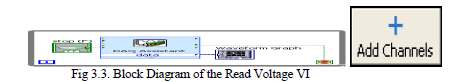
| You will use the DAQ Assistant Express VI to create a task in NI-DAQmx. NI-DAQmx is a programming interface you can use to communicate with data acquisition devices. Refer to the Getting Started with LabVIEW» Getting Started with DAQ»Taking an NI-DAQmx Measurement in LabVIEW book on the Contents tab in the LabVIEW Help for information about additional ways to create NI-DAQmx tasks. In the following exercises, you will create an NI-DAQmx task that continuously takes a voltage reading and plots the data on a waveform graph. |
G. Creating an NI-DAQMX task: |
| In NI-DAQmx, a task is a collection of one or more channels, which contains timing, triggering, and other properties. Conceptually, a task represents a measurement or generation you want to perform. For example, you can create a task to measure temperature from one or more channels on a DAQ device. |
| Complete the following steps to create and configure a task that reads a voltage level from a DAQ device. |
| 1. Open a new, blank VI. |
| 2. On the block diagram, display the Functions palette and select Express»Input to display the Input palette. |
| 3. Select the DAQ Assistant Express VI, shown at left, on the Input palette and place it on the block diagram. The DAQ Assistant launches and the Create New Express Task dialog box appears. |
| 4. Click Acquire Signals»Analog Input to display the Analog Input options. |
| 5. Select Voltage to create a new voltage analog input task. The dialog box displays a list of channels on each installed DAQ device. The number of channels listed depends on the number of channels you have on the DAQ device. |
| 6. In the Supported Physical Channels list, select the physical channel to which the device connects the signal, such as ai0, and then click the Finish button. The DAQ Assistant opens a new dialog box, shown in Figure 4-1 that displays options for configuring the channel you selected to complete a task. |
 |
H. Graphing data from a DAQ device: |
| You can use the task you created in the previous exercise to graph the data acquired from a DAQ device. Complete the following steps to plot the data from the channel on a waveform graph and change the name of the signal. |
| 1. On the block diagram, right-click the data output and select Create» Graph Indicator from the shortcut menu. |
| 2. Display the front panel and run the VI three or four times. Observe the waveform graph. Voltage appears in the plot legend at the top of the waveform graph. |
| 3. On the block diagram, right-click the DAQ Assistant Express VI and select Properties from the shortcut menu to open the DAQ Assistant. |
| 4. Right-click Voltage in the list of channels and select Rename from the shortcut menu to display the Rename a channel or channels dialog box. You also can select the name of the channel and press the <F2> key to display the Rename a channel or channels dialog box. |
| 5. In the New Name text box, enter First Voltage Reading, and click the OK button. |
| 6. In the DAQ Assistant dialog box, click the OK button to save the current configuration and close the DAQ Assistant. |
| 7. Display the front panel and run the VI. First Voltage Reading appears in the waveform graph plot legend. |
| 8. Save the VI. |
I. Editing an NI-DAQMX task: |
| You can add a channel to the task so you can compare two separate voltage readings. You also can customize the task to acquire the voltage readings continuously.Complete the following steps to add a new channel to the task and acquire data continuously. |
| 1. In the block diagram window, double-click the DAQ Assistant Express VI to open the DAQ Assistant. |
| 2. Click the Add Channels button, shown at left, and select Voltage to display the Add Channels To Task dialog box. |
| 3. Select any unused physical channel in the Supported Physical Channels list, and click the OK button to return to the DAQ Assistant. |
| 4. Rename the channel Second Voltage Reading. |
| 5. In the Timing Settings section of the Configuration page, select Continuous Samples from the Acquisition Mode pull-down menu. When you set timing and triggering options in the DAQ Assistant, these options apply to all the channels in the list of channels. |
| 6. Click the OK button to save the current configuration and close the DAQ Assistant. The Confirm Auto Loop Creation dialog box appears. |
| 7. Click the Yes button. LabVIEW places a While Loop around the DAQ Assistant Express VI and the graph indicator on the block diagram. A stop button appears wired to the stop input of the DAQ Assistant Express VI. The stopped output of the Express VI is wired to the conditional terminal of the While Loop. The block diagram should appear similar to Figure. |
 |
| 8. If an error occurs or you click the stop button while the VI is running, the DAQ Assistant Express VI stops reading data and the stopped output returns a TRUE value and stops the While Loop. |
OTHER LabVIEW FEATURES |
A. All VIS and functions: |
| The Express VIs and structures located on the Express subpalette of the Functions palette are a small subset of the complete set of built-in VIs, functions, and structures available in LabVIEW.Click the View button on the pinned Functions palette and select Change Visible Categories from the shortcut menu to display the Change Visible Categories dialog box. Then place checkmarks in the checkboxes next to the categories you want to view on the Functions palette.LabVIEW uses colored icons to distinguish between functions, VIs, and Express VIs. Icons for functions have pale yellow backgrounds, most icons for VIs have white backgrounds, and icons for Express VIs appear surrounded by pale blue fields. Express VIs appears on the block diagram as expandable nodes with icons surrounded by a blue field. Unlike Express VIs, most functions and VIs on the block diagram appear as icons rather than expandable nodes. |
B. VIs |
| You can use an existing VI or a VI you create as a subVI. When you place a VI on the block diagram, the VI is a subVI. When you double-click a subVI, its front panel appears, rather than a dialog box in which you can configure options.The icon for a VI appears in the upper right corner of the front panel and block diagram. This icon is the same as the icon that appears when you place the VI on the block diagram. You can use the default icon or create a custom icon using the Icon Editor.Refer to the Fundamentals»Creating VIs and SubVIs book on the Contents tab in the LabVIEW Help for more information about creating VIs, configuring them as subVIs, and creating icons.You also can save the configuration of an Express VI as a subVI. Refer to the Fundamentals»Building the Block Diagram book on the Contents tab in the LabVIEW Help for more information about creating subVIs from Express VIs. |
HARDWARE REQUIREMENTS |
A. DAQ: |
| DAQ is data acquisition. It is device which contains both ADC & DAC in it. It is interface between analog output of sensor and the PC. The data traditional experiments in it signal from sensors are sent to analog or digital domain, read by experimenter, and recorded by hand. In automated data acquisition systems the sensors transmit a voltage or current signal directly to a computer via data acquisition board. Software such as LabVIEW controls the acquisition and processing of such data. Here we have to consider the following properties of the input signal. |
| 1. Sampling Rate, 2. Resolution, 3. Range, 4. Amplification; Here the DAQ being used is NI USB – 6009 |
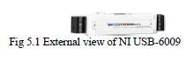
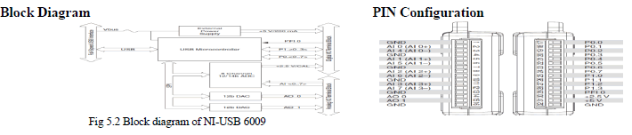
NI USB – 6009: |
 |
Description |
| The NI USB – 6009 provides connection to eight single-ended analog input (AI) channels, two analog output (AO) channels, 12 digital input/output (DIO) channels, and a 32-bit counter with a full-speed USB interface.The National Instruments USB-6009 provides basic data acquisition functionality for applications such as simple data logging, portable measurements, and academic lab experiments. It is affordable for student use and powerful enough for more sophisticated measurement applications. |
 |
SYSTEM DESIGN |
INTRODUCTION: |
| In this paper we proposed to design a very efficient system of measuring and monitoring the data of a solar panel, which has its design features dominating the previous proposed systems for data monitoring of PV panels since our project is a real time application oriented which can be implemented and function on the basis of simple design as mentioned in this section of the paper. |
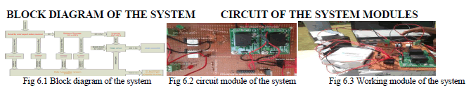 |
MODULE UNDER WORKING CONDITION: |
DISCRIPTION OF COMPONENTS USED IN DESIGN |
 |
CHARACTERISTICS: |
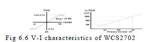 |
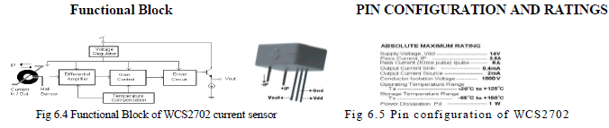
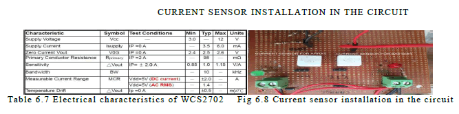
| We can observe from the V-I characteristics and from the output mode of analysis of current sensor, we can conclude that WCS2702 work on the principle of Hall Effect and the characteristics say us that voltage sensitivity of output varies linearly with the current measured in the system. And the sensitivity is in 1mV/mA. |
ELECTRICAL CHARECTERISTICS: |
 |
D. Posi t ive Vol tage Regulator LM7805 : Pin diagram |
 |
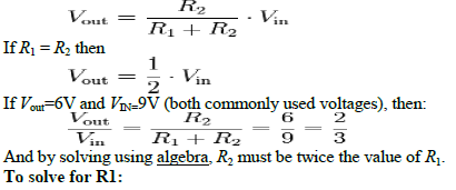
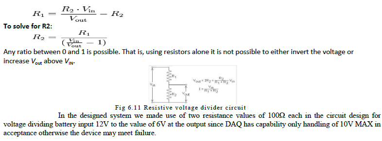
Voltage Divider Circuit: |
| In electronics or EET, a voltage divider (also known as a potential divider) is a linear circuit that produces an output voltage (Vout) that is a fraction of its input voltage (Vin). Voltage division refers to the partitioning of a voltage among the components of the divider. An example of a voltage divider consists of two resistors in series or a potentiometer. It is commonly used to create a reference voltage, or to get a low voltage signal proportional to the voltage to be measured, and may also be used as a signal attenuator at low frequencies. For direct current and relatively low frequencies, a voltage divider may be sufficiently accurate if made only of resistors; where frequency response over a wide range is required, (such as in an oscilloscope probe), the voltage divider may have capacitive elements added to allow compensation for load capacitance. In electric power transmission, a capacitive voltage divider is used for measurement of high voltage. |
RESISTIVE DIVIDER |
| A resistive divider is the case where both impedances, Z1 and Z2, are purely resistive. Substituting Z1 = R1 and Z2 = R2 into the previous expression gives: |
 |
 |
IMPLEMENTATION AND RESULTS |
A. CODE GENERATION IN LABVIEW PROGRAMMING: |
| LabVIEW is virtual programming code. So, with the usage of LabVIEW, we can write simple codes in programming them to do assigned task for it. Using MATLAB and SIMULINK, we can write codes with them which are very tedious, very lengthy codes are to be written to complete a measuring task using that software’s. The time taken for writing code in a LabVIEW is very less when compared to the above stated programming techniques. Initially to write code in the LabVIEW, we must have a keen look towards the operating symbols, and their specifications in before we start the code writing. So, for my project concern the following are necessary elements required for my coding. |
B. Block Diagram Programming Element s |
| 1. DAQ assistant to initialize the digital data collection from DAQ for my program. |
| 2. Filter to eliminate the disturbances in the graphical indications. |
| 3. Needed dynamic data converter to array module data. |
| 4. Operational mathematical elements, graphical indicators and finally a elapsed time and Wait element of time to collect data points for specified interval of time. 6.3 Observed Results in Front Panel of Labiew Monitor |
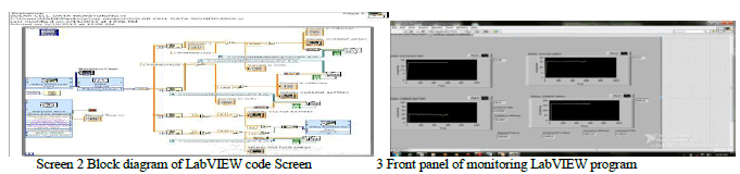 |
| 5. A wait time is necessary since in acquiring data a while loop will collect data points for each milli second (mS) of its loop termination. But a typical MS-Excel data sheet can only hold 32000 points of data so, monitoring for a long period, say 20 hrs of duration, storage will not be enough. |
| 6. so an excel sheet if operated the VI without Wait timer, the data sheet will be full with in 32 min of duration, restricting long duration of monitoring the panel. |
| 7. Elapsed timer will give us the total loop termination, making to stop the running of VI finally at end of complete monitoring. |
| 8. So, elapsed timer and wait time is essential elements for loop execution in the program. |
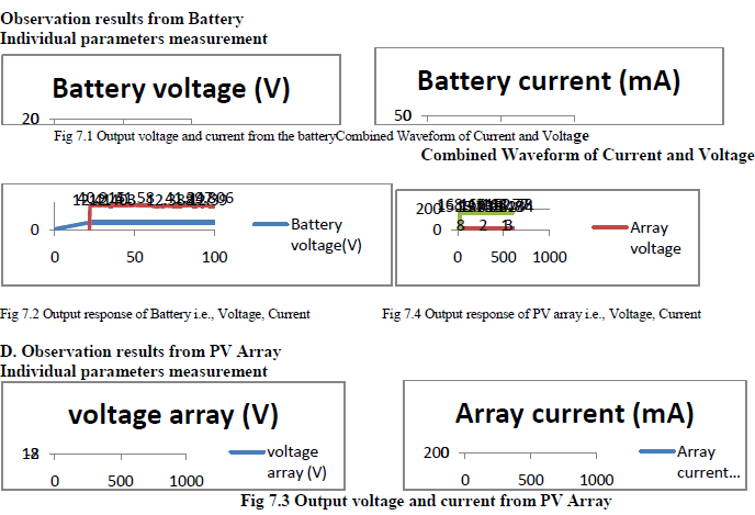
C.WAVEFORMS FROM THE SYSTEM RESULTS: |
 |
FUTURE ENHANCEMENTS |
A. Future Enhancements for Designed System: |
| From block diagram and system design we can view a switching circuit present in the design, we also implemented some voltage comparisons between battery and array with the aim of switching between these two power supply sources towards continues operation of the load. We can try to expand the design in making un-interruptible supply to the load by making switching between inverter and supply mains at the consumer end. We can also incorporate design system with addition to existing VI, determination of discharge rate of battery used for storage of solar energy.This system also could become a remote monitoring system via the Internet network. |
CONCLUSION |
| This paper investigated the design process involved in building a monitoring and data acquisition system for a rooftop photovoltaic facility. Requirements were determined according to the end-use of the data as well as current context and research opportunity in solar energy. The main interest was to produce a unique resource for study on the intermittency of PV systems, particularly in comparison to various types of photovoltaic technologies real time data monitoring. The final design incorporated various sensors, which are widely used in the energy industry. Selection of these sensors was based on meeting requirements from relevant standards, as well as achieving high time resolution monitoring of solar radiation and PV performance data. A similar approach was followed in the selection of a data acquisition system, which was configured successfully. |
References |
|