The variation in via and gap between metal sheets the electronic steer-ability is obtained by introducing the diodes between the metal patches of EBGS in the earlier stages. Here in this paper the beam configuring of the antenna by placement of EBGS as reflecting surfaces instead of the plane metal sheets around the antenna is analyzed and the beam configuration for different placements including backend of the antenna, back-right ends, back-left ends and all ends leaving front end as open is analyzed and results are illustrated in this paper. For the four proposed models return loss, radiation pattern, Gain in 3D and gain in top view are compared and presented along with some other antenna parameters.
Keywords |
| Energy band gap surfaces, reflecting surfaces, beam configuring, enhanced radiation, High impedance
ground planes |
INTRODUCTION |
| In the earlier stages we have seen the electronic beam configuration [2]. And also seen the effect of EBG when it is
used as reflecting surface around the monopole antenna in[1]. Here in this paper we mainly concentrate the beam
configuration by placing the EBGS as reflecting surfaces around the monopole antenna how the radiation around
antenna configures when we place EBGS at back end of the antenna, back-right ends, back-left ends and left-back-right
ends by leaving frontend as open. As we know that the conventional plane metal sheet reflectors suffers the minimum
distance λ/4 problem so that we use this EBGS or HIGP as reflecting planes. Where the basic agenda is to add the
surface currents of EBGS and the antenna currents to enhance the radiation in opposite direction. Here the surface
currents from each EBGS plane will add with antenna currents with some phase to configure the beam. |
ANTENNA AND EBG DESIGNS |
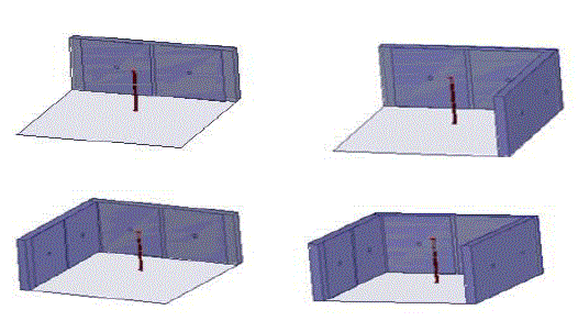
| For the isotropic antenna a monopole antenna of arm length 3.16EM is taken which is operating at 2GHZ frequency
and it‘s diameter is 0.2cm the ground is of dimensions 10.05*10.05cm and the EBG have placed vertically with a base
ground of 8.37*3.5cm in YZ directions. And the patch size for EBG is 3.5*3.5cm in YZ direction and the pin via is of
0.1cm radius and 0.5cm height. And the entire design is shown in figure [1]. |
SIMULATION RESULTS |
Return loss curves |
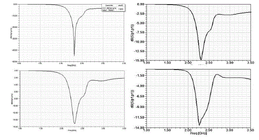
| The below figure [2] shows the return loss curves for all the four designs and the variation in the return loss for each
design can be clearly seen in the figure[2]. |
Radiation pattern curves |
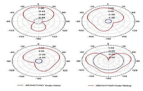
| By the placement of EBGS as reflecting planes instead of plane metal sheets we can configure beam of the antenna
which is explained in the following figure [3] where the radiation pattern curves are shown for theta = 0º and 90º where
in figure [3] a the beam is configured to front end for theta=90º when EBGS is placed at back end of antenna. In
figure[3]b the beam is configured to frontend left side in figure[3]c the beam is configure to frontend right side and finally when EBGS is placed in all side except the front side then beam is configured to front side for theta = 90
radiation is enhanced to the open side. |
Total Gain in 3D |
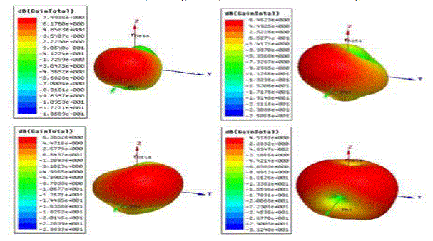
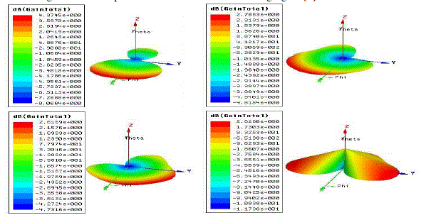
| As we know that the radiation of monopole antenna is Omni-directional. But when we place EBGS as reflecting
surface at one end the radiation may enhance in opposite direction or absorbed it is explained in [4]. Here the figure
[4]a,b,c, and d shows the EBGS at back end, back-right ends, back-left ends and left-back-right ends. By seeing the above figure [4] we can say that according to the EBGS existence at each side’s the radiation is
contributed maximally at opposite side to reflecting planes. |
Total Gain in top view |
| For easy understanding the Gain in top view is illustrated in the following figure [5]. |
| By the above figure we can say that gain is enhanced in opposite direction of the EBGS in figure [5] a and in figure [5]
b the EBGS are placed at back-right ends so gain is improved in frontend left side. In Figure [5] c the EBGS are placed
at back-left ends so gain is improved in frontend right side. In figure [5] d EBGS are placed in three places so gain is
momentarily enhanced in both frontend right and left sides. |
| The above table illustrates the comparison between the antenna parameters for the four designs and by the table we can
see that each time when the no. of EBGS around antenna increase the energy from antenna are absorbed by the EBGS
up to some extent . |
CONCLUSION |
| The beam configuration by EBGS reflecting surfaces is analyzed and the possibility of EBGS surfaces currents
adding to antenna currents with some phase to form the beam is explained the future scope is to steer or configure the
beams with mechanical steering capability instead of varying the via length and gap between the metal sheets each
time. We may steer the radiation energy by variation in placement of each individual EBGS cell. |
| |
Tables at a glance |
 |
| Table 1 |
|
| |
Figures at a glance |
 |
 |
 |
 |
 |
| Figure 1 |
Figure 2 |
Figure 3 |
Figure 4 |
Figure 5 |
|
| |
References |
- J. Doondi kumar , ―Analysis of Monopole Antenna by Placing High Impedance Absorber Surface at one Sid /Volume-2Number-1PP-
317-321.pdf
- Filippo costa, An active High impedance surface for low profile Tunable and steerable Antennas, IEEE ANTENNAS AND WIRELESS
PROPAGATION LETTER, VOL 7, 2008.
- Y. Kotsuka, M. Amano, ―Broadband EM Absorber Based on Integrated Circuit Concep, Microwave Symposium Digest, 2003 IEEE
MTTS International, Volume 2, 8-13 June 2003 Page(s):1263 âÃâ¬Ãâ 1266 vol.2.
- C. Balanis, Antenna theory, Analysis, and Design 2nd ed., John Wiley and sons, New York (1997)
- Kern, D.J.; Werner, D.H.; Monorchio, A.; Lanuzza, L.; Wilhelm, M.J., ―The design synthesis of multiband artificial magnetic
conductors using high impedance frequency selective surfaces,IEEE Transaction on Antennas and Propagation, Volume 53, Issue 1, Part 1, Jan. 2005 Page(s):8 âÃâ¬Ãâ 17.
- Sievenpiper, D. F., \High-impedance electromagnetic surfaces," Doctorate thesis, University of California, 1999.
- D. Sievenpiper, ―High - Impedance EM surface, Ph.D. Dissertation, University of California, Los Angeles, 1999.
- D. Sievenpiper, E. Yablonovitch, U.S. provisional patent application, serial number 60/079953, filed on March 30,1998.
- J. Doondi kumar , Enchancing And Directing Radiation With Planar And Ebg Reflectors, IJERD : Volume 7, Issue 5.
- J. Doondi kumar , ―Design and Analysis of C0-axial Feed Rectangular Patch Antenna on High Impedance Surfac /Volume-2Number-1PP-405-410.pdf
|