ISSN ONLINE(2278-8875) PRINT (2320-3765)
ISSN ONLINE(2278-8875) PRINT (2320-3765)
Sophia Markose1, Siva Subba Rao Patange2, Raja S2, Salice Peter1
|
| Related article at Pubmed, Scholar Google |
Visit for more related articles at International Journal of Advanced Research in Electrical, Electronics and Instrumentation Engineering
A Micro Air Vehicle (MAV), or Micro Aerial Vehicle, is a class of Unmanned Aerial Vehicles (UAV) that has a size restriction and may be autonomous or remote controlled mode of operation. Modern craft can be as small as 15 centimeters. The small craft allows remote observation of hazardous environments, inaccessible to ground vehicles. For efficient flying of modern MAVs, the control surface movements of MAV is replaced with Macro Fiber Composite (MFC) in place of servo mechanism as control actuator. This actuator works with the voltage range of -500 to 1500V. The controlling signal is sent through the radio control transmitter. The receiving side (MAV) has an antenna through which it receives the radio signals. In this paper the received radio signals in the form of PWM were converted to DC voltage in the range of 0-5V by developing a PWM to voltage converter. For actuator movement of MFC a high voltage DC-DC converter is required. The DC-DC converter for the range-500 to 1500V was designed using upconverted PWM signal. Input voltage for all designed electronics has to be powered by a 12V MAV battery. The switching action of the DC- DC converterneeds to generate the output based on the signal input from the PWM. The designed DC-DC converter was evaluated by using Simulink simulation results.
Keywords |
| MAV, MFC, RC signal, RC-DC Converter, ARM Cortex-M3, Fly back DC-DC converter |
INTRODUCTION |
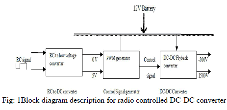
| Soldiers, Special Weapons And Tactics (SWAT) teams, and natural disaster first respondersare examples of teams of people operating in dangerous and potentially hostile environmentswho quickly need information about their local environment. These personnel often quicklyneed aerial imagery of their environments to answer relatively simple questions such as,"Ismy path blocked?" or "Is there a threat on top of that building?" The use of Micro AirVehicles (MAVs) to support such personnel has become common place in the military operations.Micro Air Vehicle or Micro Aerial Vehicle is a class of Unmanned Aerial Vehicle (UAV)that are used in such operations. Anew trend in MAV community is to take inspiration from flying insects or birds to achieve flying capabilities[1].Based on the mode of operation, the MAVs are classified in to two types namely remote controlled and autonomous mode. In autonomous operation the controlled path for the flight is predetermined and Remote Control (RC) station is not required. But inremote controlled mode, the direction of movement is controlled from a RC station. According to the signal received from RC, MAVs has to change its direction using actuators. Micro FiberComposite (MFC) is one such type of actuator used for MAV application[2]. This actuator workswith the voltage range of -500 to +1500V. In the present work a circuit was developed and the design was simulated for the generation of -500 to +1500V from a radio controlled (RC) signal as shown in Fig: 1. |
 |
RC-DC CONVERTER |
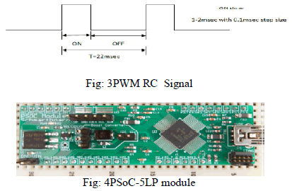
| In the RC mode of operation of MAV,the controlled maneuvers are carriedout fromground station. The standard radio controlledsignals are Pulse Width Modulated (PWM)signalwith pulse width varies from 1.0 to2.0msec. The frequencyof the PWM signal rangesfrom 25-125Hz for the HobbyKing 2.4Ghz 4Ch Tx&Rx V2 transmitter, whichis usedin the present work. The receiver output signal frequency is 45.45Hz.This RC signal is in the form of PWM signal that has duty cycle variation from 4 to 9%. Based on the ON time variation of RC signal, voltage has to be generated from 0-5V.Hence full duty-cycle variation of the PWM signal is utilized in the designed RC-DC converter. |
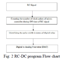
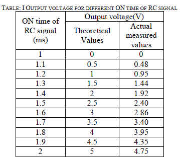
| In the design of converting the voltage, the step size for ON time variation is selected as0.1msec. That means for 1.1msec ON time of RC signal, the output voltage has to generate 0.5V,for 1.2msec the output is 1V. Similarly voltage output for the variation of ONtime of RC signal is shown in Table: 1. Micro-controller based converter is used for the development of RC-DC converter.Flow chart for micro-controller program is shown in Fig: 2. Theimplementation of the logic was carried using Programmable System on Chip(PSoC) configuration.A cypress PSOC 5LP ARM based board has been used for this purpose. |
| PSoC 5LP is a true programmable embedded system-on-chip, integrating configurableanalog and digital peripherals, memory, and a micro-controller on a single chip. The PSoC5LP have 32-bit ARM Cortex-M3 core plus DMA controller, digital filter processor withoperating frequency up to 80 MHz andprogrammable digital and analog peripherals withflexiblerouting so that any analog or digital peripheral function can be programmed as any PIN of the kind[3]. |
 |
| Besides compact PSoC, it is a highly configurable system-on-chip architecture for embeddedcontrol design. It is possible to configure analog and digital circuits by programming the on-chip microcontroller. A single PSoC device can integrate as many as 100 digital andanalog peripheral functions, this inturnreduces design time, board space, power consumption, andsystem cost with improving system quality. |
HARDWARE IMPLEMENTATION - RC-DC CONVERTER |
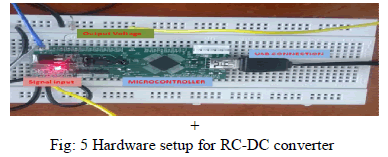
| The input for RC-DC converter is the PWM signal, received by the receiver unit. The waveform of the signal is shown in Fig: 3. The output voltage of the PSoC will be varied based on the ON time of the PWM signal. The Cypress PSoC 5LP development board is used as shown as in Fig:4. The logic implementation is carried out by using the embedded software called PSoC Creator. |
| PSoC Creator is a free version Windows-based Integrated Design Environment (IDE). It enables concurrent hardware and firmware design of PSoC 3, PSoC 4, and PSoC 5LP based systems.It supports design implementationsfor hundred100 pre-verified,production-ready PSoC Components as well as the custom based design logics. ThePSoC Creator simplifies the hardware system design just by drag and drop of component icons in the maindesign work space. Co design of the applicationis the firmware can be developed by using the PSoC CreatorIDE C compiler [4]. |
 |
| The compiled logic program is loaded into the PSoC board using a flash burner programmer through USB connector. Through USB the PSoC- 5LP can be powered up and this illuminates on-board the LED as shown in Fig.5. The RC(PWM)signal from the receiver was connected as the input to the PSoC board using external connector/wires. Entire connection setup for RC-DC converter is shown in Fig: 5.The on-board Digital to Analog Converter(DAC) which is Integrated Digital to Analog Converter (IDAC) converts the ON time of the PWM pulse to voltage output. The output voltage is then measured across a externally connected 10Kohm resister using Digital storage oscilloscope(DSO). |
 |
RC -DC CONVERTER RESULTS |
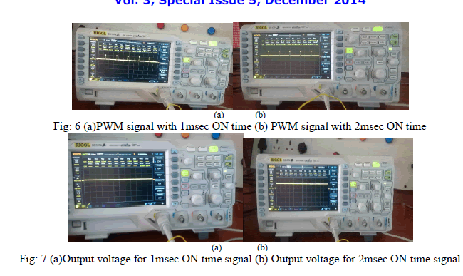
| RC signal received from the transmitter ground station was measured at the receiver end using DSO, which is shown in Fig: 6. Fig. 6(a) shows the PWM signal for 1msec ON time and where as Fig: 6(b) shows for 2msec. The corresponding output voltages are shown in Fig:7(a) and Fig: 7(b) and the voltage readings are presented in the Table I. Allthe measurements were carried out using RIGOL DS1074 DSO with 1:1 probe setting. |
 |
 |
CONTROL SIGNAL GENERATOR-PWM |
| This RC signal of the receiver is in the form of PWM signal and has a duty cycle variation from 4 to 9%. So, itcannot control the generation of higher range of voltage required to control the MFC. Frequency required for switching the flyback converter is in the range of KHz. So the RC signal has to be converted as switching signal in KHz range. For this initial requirement is to necessary to convert the duty-cycle from 0 to100%. Based on the ON time variation of RC signal, voltage is generated by using RC-DC converter(0-5V).Hence full duty-cycle variation can be achieved using the designed RC-DC converter voltage. |
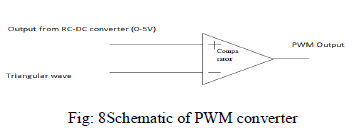
| Flyback converter switching signal should be a constant frequency signal with varying duty-cycle in KHz range. But RC-DC converter output is a analog voltage signal. From thisduty-cycle varying signal has to generate with the variation of voltage value. This can be achieved by using a PWM generator. General form of a PWM generator is a comparator as shown in Fig: 8.The control signal PWM generator is designed using Mathlab Simulink. |
 |
DC-DC CONVERTER |
| The operation voltage required for Macro Fiber Composite(MFC) is in the range of -500 to +1500V. So this voltage rangehas to be generate from a 12V battery using control signal from the PWM generator. This isachieved by using a Flyback DC-DC converter. The reason for selecting the flyback converter isthat it can provide DC isolationof upto 5000V. so, it is best suitable for MAV applications and also it is possible to design one or more output voltages from a single transformer. The output can be either positive or negative in voltage. |
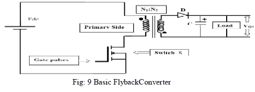
| Fly-back converter is the most commonly used SMPS circuit for low output power applications where the output voltage needs to be isolated from the input main supply. The output power of fly-back type SMPS circuits may vary from few watts to less than 100watts. The commonly used flyback converter requires a single controllable switch like, MOSFET and the usual switching frequency is in the range of 100 kHz. Fig: 9 shows the basic topology of a flyback circuit[5]. When the switch is turned ON energy is stored in the primary. The polarity dots on the transformer and the diode are arranged in such a way that there is no energy transferred to the load when the switch is ON. When the switch is OFF the polarity of the transformer winding reverses due to the collapsing magnetic field, the output rectifier conducts and the energy stored in the core material is transferred to the load. This activity continues until the core is depleted of energy or the power switch is once again turned ON[6-13]. |
 |
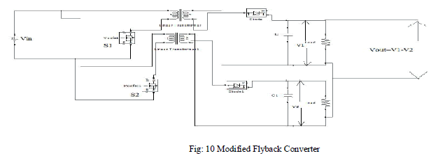
| For getting higher output voltage, the basic flyback converter circuit is modified as shown in Fig: 10. It contains two flyback converters with one input source and one control signal for two switches. The two flyback converters operate simultaneously such that oneis with duty-cycle D and the other is with (1-D). Output voltage across the load is taken asVout = (V1 -V2). So that it is able to get both positive and negative voltages according to V1 andV2. |
 |
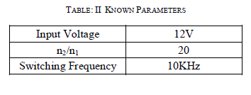
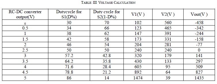
| For designing the modified flyback converters parameters selected are as shown in Table II.Based on these the output voltage can be calculated using the equation 1. Flyback converter output voltages for the input voltage 0-5V from RC-DC converter for corresponding duty cycle variations is shown in Table III. |
 |
 |
 |
SIMULATION RESULTS |
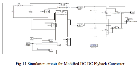
| Simulation of designed flyback converter was accomplished using MATLAB Simulink. The entire Simulation circuit is shown in Fig: 11. It includes control PWM generator and dc-dc converter.Flyback converter simulated with different duty cycles and the result obtained are shown in figures: 12,13,and 14. |
 |
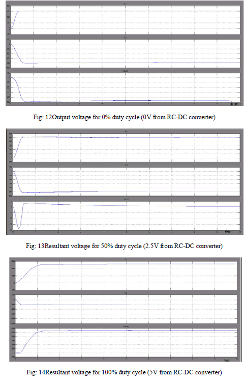 |
| From the simulation results, it is clear that for 1msec duration of ON time of RC signal,the output voltage from DC-DC converter is -455V as compared to theoretical calculated value of -458V which is required to bias the MFC actuator. Similarly for 1.5msec ON time of RC signal simulation outputis 0V and for 2msec ON time duration of RC signal i.e. 100% duty cycle and voltage output from RC-DC converter was about 5V the output notice is around1150V . |
CONCLUSION |
| Microcontroller based RC-DC and DC-DC controlling circuit has been developed for accurate movementofcontrol surface of MAV using MFC actuator.Using PSoC 5LP development board the hardware implementation was carried out and the results were compared. The DC-DC converter was designed in the MATLAB Simulink environment and verified for the output range -455 to 1150 volts. It is observed that by increasing the input battery source voltage the output was increased proportionally for the DC-DC converter. |
ACKNOWLEDGMENT |
| Authors would like to thank Mr. ShyamChetty, Director CSIR-NAL, Dr.Satish Chandra,Head STTD, CSIRNAL for their help and encouragement and Prof K Radhakrishnan, Head of the Department,Electrical & Electronics, M A College of Engineering,Kothamangalam, Kerala for the encouragement to carry out this work. |
References |
|