International Journal of Advanced Research in Electrical, Electronics and Instrumentation Engineering
ISSN ONLINE(2278-8875) PRINT (2320-3765)
ISSN ONLINE(2278-8875) PRINT (2320-3765)
Rajan P Thomas1, Jithin K K2, Hareesh K S3, Habeeburahman C A4,Jithin Abraham5
|
| Related article at Pubmed, Scholar Google |
Visit for more related articles at International Journal of Advanced Research in Electrical, Electronics and Instrumentation Engineering
The proposed system „The Ultrasonic Range Detector‟ employs an ultrasonic module that consists of an ultrasonic transmitter and receiver along with anATmega16a microcontroller. It works by transmitting a short pulse of sound at a frequency inaudible to the ear (ultrasonic sound or ultrasound). Afterwards the microcontroller listens for an echo. The time elapsed during transmission to echo reception gives information on the distance to the object. We aimed at designing rangefinder free from the conventional problems arising from the undesirable direct waves, wherein a signal level for detecting a right signal due to the reflection waves from a ranging object is automatically varied and the detection of the right signal is made inaccurate by the time-dependent signal level.
Keywords |
| Range finder, Distance Measurement, Ultrasonic Module, Microcontroller, ATmega16a, WinAVR. |
INTRODUCTION |
| The easy and accurate measurement of distance has been major subject of study in the field of engineering and physics from the time men began to walk on earth. Many different techniques have been devised till date for the measurement of distance from the observer to a target, for the purposes of surveying, navigation, determining focus in photography, or accurately aiming a weapon. Manual distance measuring is always done at the expense of human error. Employing electromagnetic waves for distance measurement [1] gathered significance with the advent of research in the field of electromagnetism. The use of infra-red rays presents a simpler solution for the question at hand, while the cost of this simplicity arises in the form of a very low range and a significant error in the result. Here is when the technique proposed in the paper comes in. The proposed system employs ultrasonic waves for distance measurement, the highly directional properties of the wave and comparatively lower attenuation encountered makes it highly suited for distance measurement. |
| Objective of the proposed technique was to develop a device based on a highly that can be used to measure the distance [1] of the target with high precision using ATmega16a as a processor. Focus has been given on lower ranges considering the range of 1cm to 2.5m with the precision of ±0.1cm using standard ultrasonic transducer HC SR04.For contact less measurement of distance, the device has to rely on the target to reflect the pulse back to itself. The target needs to have a proper orientation that is, it needs to be perpendicular to the direction of propagation of the pulses. The amplitude of the received signal gets significantly attenuated and is a function of nature of the medium and the distance between the transmitter and target. The pulse echo or time-of-flight method of range measurement is subject to high levels of signal attenuation when used in an air medium, thus limiting its distance range. |
PRINCIPLE |
| An Ultrasonic transducer uses the various physical properties of ultrasound of a specific frequency. The ultrasonic transducers are available in piezoelectric and electromagnetic makes. The piezoelectric type is generally preferred due to its lower cost and simplicity to use [1]. It is capable to transmit and receive the ultrasonic signal of a required strength. The Ultrasonic wave propagation velocity is subject to temperature of the medium, in the air it is approximately 340 m/s at 15°C of air or atmospheric temperature, the same as sonic velocity. The velocity (V) may be computed as a function of temperature as shown. |
| V= 340+0.6(T-15) m/s, Where, T= temperature, °C |
| Here a room temperature of 20°C is assumed; hence the velocity of ultrasound in the air is taken as 343 m/s. Because the travel distance is very short, the travel time is not affected by temperature to a greater extend. The distance travelled by the wave at time t seconds can be given by |
| Distance (D) = k*V*t,where k- correction factor |
GENERAL OVERVIEW AND WORKING OF THE SYSTEM |
| The measurement process is initiated by sending a trigger signal to the ultrasonic module. When the reset pulse is given to the processor, it produces a trigger pulse of 15 μs and transfers to the HC-SR04 ultrasonic module [2]. The trigger signal must be a pulse with 10μS high time. When the module receives a valid trigger signal it issues 8 pulses of 40 KHz ultrasonic sound from the transmitter. The echo of this sound is picked by the receiver, after getting the echo of the ultrasonic sound, the module produce a signal at the echo pin whose high time is proportional to the distance to be measured. |
| Test distance = (high level time × velocity of sound (340M/S)) / 2 |
| Distance in cm = echo pulse width in μs/58 |
| Distance in inch = echo pulse width in μs/148 |
| Finally the distance calculated based upon the pulse width of the echo signal is send to the LCD segment and the range is displayed in centimetres. This ultrasonic rangefinder can measure distances up to 2.5 meters at an accuracy of 0.1 centimetre. |
METHODOLOGY |
| The system design required familiarisation with adopted technologies for contactless range determination. The flaws in the infrared based system and the advantages of employing an ultrasonic wave based system was analysed in detail by referring to the systems designed based on these technologies. Comparisons were made and the technique was finalised. |
| Extensive literature survey was conducted to determine the best suited components for the system to be fabricated. Program code [3] and the hardware design [4] were completed after considering the required system performance and the constraints like range temperature etc. |
A. HARDWARE DESIGN |
| The system hardware may be broadly classified into two sections i) Digital section and ii) Analog section. The basic hardware structure can be understood from conceptual block diagram is shown in Fig. 1. |
| Fig. 1 Conceptual diagram of the system |
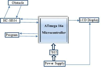 |
| 1)Digital Section: - The digital section consists of the microcontroller and LCD unit with the 5V power supply derived from the 7805 voltage regulator IC. |
| a. ATmega16a Microcontroller: - The AVR ATmega16 [5] is a low-power CMOS 8-bit microcontroller based on the AVR enhanced RISC architecture [6]. By executing powerful instructions in a single clock cycle, the AVR ATmega16 achieves throughputs approaching 1 MIPS per MHz allowing the system designer to optimize power consumption versus processing speed. The important features of ATmega16a [6] includes 16K bytes of In-System Programmable Flash Program memory with Read-While-Write capabilities, 512 bytes EEPROM, 1K byte SRAM, 32 general purpose I/O lines, 32 general purpose working registers, a JTAG interface for Boundaryscan. On-chip Debugging support and programming. Three flexible Timer/Counters with compare modes, Internal and External Interrupts [5], A serial programmable USART, A byte oriented Two-wire Serial Interface, an 8-channel 10-bit ADC with optional differential input stage with programmable gain (TQFP package only), a programmable Watchdog Timer with Internal Oscillator, an SPI serial port, and six software selectable power saving modes. |
| b. LCDisplay:- A 16x2 Liquid Crystal Display is a low power, low cost, basic electronic display.A 16x2 LCD means it can display 16 characters per line and there are 2 such lines. In this LCD each character is displayed in 5x7 pixel matrix. This LCD has two registers, namely, Command and Data. The command register stores the command instructions given to the LCD. A command is an instruction given to LCD to do a predefined task like initializing it, clearing its screen, setting the cursor position, controlling display etc. The data register stores the data to be displayed on the LCD. The data is the ASCII value of the character (measured distance) to be displayed on the LCD. |
| 2)Analog Section:-The analog system consists of the ultrasonic module which consists of the ultrasonic transmitter and the receiver. |
| a. HC-SR04 Ultrasonic Module: - HC-SR04 is an ultrasonic ranging module [2] designed for embedded system projects like this. It has a resolution of 0.3cm and the ranging distance is from 2cm to 500cm. It operates from a 5V DC supply and the standby current is less than 2mA [2]. The module transmits an ultrasonic signal, picks up its echo, measures the time elapsed between the two events and outputs a waveform whose high time is modulated by the measured time which is proportional to the distance. The supporting circuits fabricated on the module makes it almost stand alone and what the programmer need to do is to send a trigger signal to it for initiating transmission and receive the echo signal from it for distance calculation. The HR-SR04 has four pins namely Vcc, Trigger, Echo, GND [2]. |
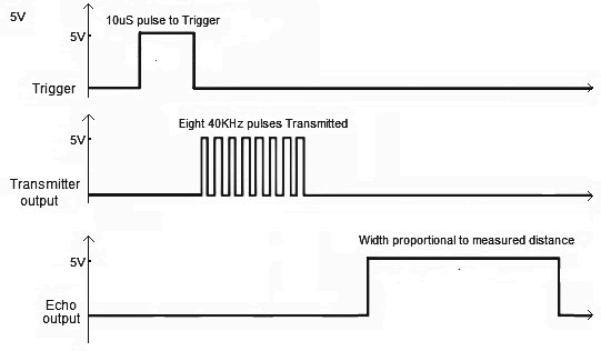 |
| Fig. 2 HC-SR04 Timing diagram |
| From the timing diagram, you can see that the 40 KHz pulse train is transmitted just after the 10uS triggering pulse and the echo output is obtained after some more time. The next triggering pulse can be given only after the echo is faded away and this time period is called cycle period. The cycle period for HC-SR04 must not be below 50mS. According to datasheet [2], the distance can be calculated from the echo pulse width using the following equations. |
| Distance in cm = echo pulse width in μs/58 |
| Distance in inch = echo pulse width in μs/148 |
B. SOFTWARE DESIGN |
| The program design for ATmega16a was done in C language [7]. It is easy to develop and implement Atmega16a program in C language [5] due to its flexibility, easiness of programming and debugging. The program [3] was burned to the ATmega16a microcontroller [4] using the USBASP programmer. The compilation of C language program to hex file was done using the popular GNU based WinAVR GCC [5]. It offers additional functionality of burning the program to the IC. The USBASP programmer [7] utilizes the In Serial Programming capability of AVR microcontrollers and thus makes it possible to program the IC real-time during development. The flow chart of the program is shown in Fig 3. |
C) INTEGRATION OF HARDWARE AND SOFTWARE |
| Once the hardware is setup, the program is burned to the ATmega16a IC using the IC programmer. The power supply is given from mains through LM 7805 voltage regulator which regulates the input voltage to +5V level. The system can work well with battery also. |
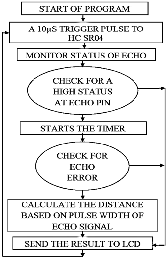 |
| Fig. 3 Flow Chart of the Program |
RESULT AND ANALYSIS |
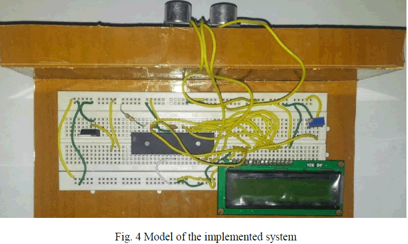
| The working model of the proposed AVR Atmega16a microcontroller based range finder using ultrasonic module was successfully designed and implemented. Fig 4 shows the circuit implemented on a breadboard. The performance of the circuit was analysed for different conditions. The circuit was able to measure distance up to 2.5m without interfering in human activity. Circuit was tested for measurement of various distances in different atmospheric conditions, accurately. It has a fast response. The ultrasonic module works fine. It responds to the incoming echo accordingly. By using ATmega16a and HC-SR04 we were able to reduce the cost and increase efficiency. This implementation has been a major component [8] in the circuits of major fast consuming electronic goods. |
 |
CONCLUSION |
| The paper presents a low-cost, low power and simple system for distance measurement. The precision of the result high compared to other conventional methods. Fig. 4 shows the model of this paper implemented. It is certainly a reliable and efficient method for instantaneous measurement of distance. Since the system remained unaffected with the human activity. This system will have high application in civil and mechanical field of engineering [9] [10] where it has been a bigger challenge for precise measurement of small and physically unreachable distances. It will surely have influence on small and large technicians who find measurements challenging in different severe environments. The future modification may include addition of speaker for distance announcement, portable device etc. |
ACKNOWLEDGMENTS |
| We hereby express our sincere gratitude to the Head of the Department of Electrical And Electronics Engineering, Prof. K. Radhakrishnan for providing us with the necessary arrangement for the completion of our project. We also thank our faculty advisor Prof.Bindu Elias for her valuable guidance. We express our sincere gratitude to our guide Asst. Prof.Jeena Joy, Department of Electrical And Electronics Engineering, without whose valuable guidance and support the project would not have been a success. We thank her for the good will and encouragement extended to us. We also thank Asst. Prof.Eldhose K A and Asst. Prof Siny Paul who have always supported us with their valuable suggestion. |
References |
|