International Journal of Advanced Research in Electrical, Electronics and Instrumentation Engineering
ISSN ONLINE(2278-8875) PRINT (2320-3765)
ISSN ONLINE(2278-8875) PRINT (2320-3765)
Mohsin Mahmood1, Om Shivam2, Pankaj Kumar3, Gopal Krishnan4
|
| Related article at Pubmed, Scholar Google |
Visit for more related articles at International Journal of Advanced Research in Electrical, Electronics and Instrumentation Engineering
Energy losses occur in the process of supplying electricity to consumers due to technical and commercial losses. The technical losses are due to energy dissipated in the conductors and equipment used for transmission, transformation, subtransmission and distribution of power. These technical losses are inherent in a system and can be reduced to an optimum level.This paper presents a study on technical losses in distribution system and analysis of the impact of losses in power sector.The technical losses caused by material properties and its resistance to the flow of electrical current in distribution system will be analyzed and simulated through electrical transient analysis program. Moreover, the impact of different types of transformer and other equipment’s connections to the substation and feeder will also be investigated
Keywords |
| Energy dissipated, Transmission, Technical losses, Distribution System, Transformers |
INTRODUCTION |
| Power is generated for the consumer utilization. From when power is generated it is transmitted through transmission lines via grids & then distributed to the consumer. Power distribution is the final and most crucial link in the electricity supply chain and most visible part of the electricity sector, according to Power Grid Corporation of India Limited current distribution losses is about 30%. Distribution losses can be caused by theft of electricity, low metering levels and poor financial health of utilities with low cost recovery, which generally causes power quality issues and increase in the cost to electricity supply. Loss of power in distribution sector also causes increase in cost to produce more power, and the global warming concerns. Distribution losses can be classified into categories of Technical losses and Non-Technical losses. The technical losses are most visible losses because it is related to material properties and its resistance to the flow of current that is also dissipated as heat. The technical losses can be clearly classified as the losses in power dissipated in distribution lines and transformers due to their internal resistance. |
| The deregulation and privatization are posing new challenges to the distribution systems. System elements are going to be loaded up to their thermal limits, and wide-area power trading with fast varying load patterns will contribute to an increasing congestion. About 30 to 40 % of total investments in the electrical sector go to distribution systems, but nevertheless, they have not received the technological impact in the same manner as the generation and transmission systems. Nevertheless, there is an increasing trend to automate distribution systems to improve their reliability, efficiency and service quality. Ideally, losses in an electric system should be around 3 to 6%. In developed countries, it is not greater than 10%.However, in developing countries, the percentage of active power losses is around 20%; therefore, utilities in the electric sector are currently interested in reducing it in order to be more competitive, since the electricity prices in deregulated markets are related to the system losses. In India, collective of all states, in 2008 the technical and nontechnical losses are accounted as 23% of the total input energy. To manage a loss reduction program in a distribution system it is necessary to use effective and efficient computational tools that allow quantifying the loss in each different network element for system losses reduction. |
EXISTING SCENARIO |
| Generation of power is done in the power stations with different fuels. Now there is huge contribution of renewable energy sources in power generation sector. In India the main source of power generation is thermal, hydro and nuclear, with a small contribution of renewable. The developing sector in power generation is nuclear and renewable sources. In this regard we cannot depend on the renewable as it is weather driven and discontinuous. But the power generation is necessary. Conventional fossil fuels power plants can be operated in accordance with the needs of power generation. Renewable energy sources such as wind and solar are variable and thus the operating schedules of such plants are largely dedicated by the changing “fuel” supply. In India only 32.86% [2] of total energy generation is contributed by the renewable energy sources including hydro power generation. This is especially pertinent in the case of wind, photovoltaic solar and run-of-the-river hydro, none of which have inherent storage in their power plant design. These systems cannot be controlled in the same manner as a conventional generation facility. |
| In the recent years, India’s energy consumption has been increasing at one of the fastest rates in the world due to population growth and economic development. India ranks fifth in the world in terms of primary energy consumption, accounting for about 3.5%of the world commercial energy demand. Despite the overall increase in energy demand, per capita energy consumption, India is still very low compared to other developing countries. India is well-endowed with both exhaustible and renewable energy resources. India’s energy policy, till the end of the 1980s, was mainly based on availability of indigenous resources. Coal was by far the largest source of energy. However, India’s primary energy mix has been changing over a period of time. Despite increasing dependency on commercial fuels, a sizeable quantum of energy requirements (40% of total energy requirement), especially in the rural household sector, is met by noncommercial energy sources, which include fuelwood, crop residue, and animal waste, including human and draught animal power. However, other forms of commercial energy of a much higher quality and efficiency are steadily replacing the traditional energy resources being consumed in the rural sector. Resource augmentation and growth in energy supply has not kept pace with increasing demand and, therefore, India continues to face serious energy shortages. This has led to increased reliance on imports to meet the energy demand. |
| Energy losses occur in the process of supplying electricity to consumers due to technical and commercial losses. The technical losses are due to energy dissipated in the conductors and equipment used for transmission, transformation, sub- transmission and distribution of power. These technical losses are inherent in a system and can be reduced to an optimum level. The losses can be further sub grouped depending upon the stage of power transformation & transmission system as Transmission Losses (400kV/220kV/132kV/66kV), as Sub transmission losses (33kV /11kV) and Distribution losses (11kV/0.4kv). The commercial losses are caused by pilferage defective meters, and errors in meter reading and in estimating unmetered supply of energy. |
| In India, average Transmission and Distribution losses, have been officiallyindicated as 23 percent of the electricity generated. However, as persample studies carried out by independent agencies including TERI, these losses have been estimated to be as high as 50 percent in some state.The officially declared transmission and distribution losses in India have gradually risen from about 15 percent up to the year 1966-67 to about 23 percent in 1998-99. The continued rising trend in the losses is a matter of serious concern and all out efforts are required to contain the them. According to a study carried out by Electric Power Research Institute (EPRI) of the USA some time back, the losses in various elements of the T&D system usually are of the order as indicated in Table I. |
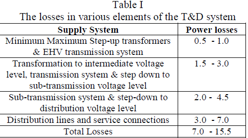 |
| The losses in any system would, however, depend on the pattern of energy use, intensity of load demand, load density, and capability and configuration of the transmission and distribution system that vary for various system elements. |
| Experience in many parts of the world demonstrates that it is possible to reduce the losses in a reasonably short period of time and that such investments have ahigh internal rate of return. A clear understanding on the magnitude of technical and commercial losses is the first step in the direction of reducing T&Dlosses. This can be achieved by putting in place a system for accurate energy accounting. This system is essentially a tool for energy management and helps in breaking down the total energy consumption into all its components. It aimsat accounting for energy generated and its consumption by various categories ofconsumers, as well as, for energy required for meeting technical requirement ofsystem elements. It also helps the utility in bringing accountability and efficiencyin its working. |
DISTRIBUTION NETWORK |
| The primary distribution networks are electrical circuits with three-phase wire(three phase), connected at distribution substation and are usually built in classes of voltage of 11KV & 33KV. The levels of voltage: 11 KV and 33 KV are standardized by law; the other levels exist and continue to operate normally. Primary distribution networks are installed with distribution transformers, fixed on poles, whose function is to lower the voltage level to the primary side voltage level (e.g., for download from 11 KV to 230 volts). The secondary distribution networks are electrical circuits with three-phase four wires (three phases and neutral), typically operate at voltages (phase - phase / phase - neutral) 11KV/440 volts, 11KV/230 volts. These networks are connected consumers, including residences, bakeries, shops, and so on, and also the fixtures for street lighting. These networks serve the large consumption centres (namely, population and large industry, among others). In some cases, the tension between supplies is 1100/230 volts or 1100/440 volts. The entire distribution system is protected by a system composed by circuit breakers at the substations where the primary networks are connected, and with key fuse in distribution transformers, which in case of short circuit switch off the power grid. |
DISTRIBUTION LINE LOSSES |
| The amount of energy loss in electrical distribution system is one of the key measures of distribution system performance as it has a direct impact on the utility’s bottom line. Distribution system’s losses can be attributed to technical and non-technical. Non-technical losses are those associated with inadequate or missing revenue metering, with problems with billing or collection systems, etc. Technical losses in the system are inherently influenced by component and system designs. |
| Since losses represent a considerable amount of operating cost, accurate estimation of electrical losses enables to determine with greater accuracy the operating costs for maintaining supply to consumers. This in turn enables a more accurate estimate of system lifetime costs, over the expected life of the installation. It is also critical to know if the expected target of technical losses is indeed technical, whether it is possible for reduction without changing the components and system design. Lower technical losses will provide for cheaper electricity and lower production costs, with a positive influence on economic growth. Various studies have been conducted over the years to calculate energy losses in distribution network. Typically, in technical loss estimation studies, the technical loss level is estimated using simulations of the network. However these studies would require complete set of data to estimate the technical loss level. In this paper, the proposed approach is conductors used, transformer relocation & capacitor installation in medium voltage feeders of different characteristics are first established. Subsequently, technical losses for each medium voltage feeder are estimated based on user input peak demand, load factor, and feeder length. An analytical expression incorporating weight-age factors, calculated by taking the ratio of energy flow through each feeder against the total energy supplied to the system is used to estimate technical losses contributed by the respective medium voltage network. Technical losses in distribution transformers are estimated based on empirical formulas of no load and full load loss scaled by capacity factors. For low voltage network, its technical losses level is primarily influenced by its percentage loading, besides load factor and network type (overhead or underground). |
| The term “distribution line losses” refers to the difference between the amount of energy delivered to the distribution system and the amount of energy customers are billed. It is important to know the magnitude and causality factors for line losses because the cost of energy lost is recovered from customers. Between 30 and 40 % of total investments in the electrical sector goes to distribution systems, but nevertheless, they have not received the technological impact in the same manner as the generation and transmission systems. Calculations of losses in power systems have been attempted since long. Earlier efforts concentrated on energy loss estimation on a yearly basis and power loss estimations for maximum load situations. The estimated losses were important data when calculating the energy losses and planning grids. There is no difference between a transmission line and a distribution line except for the voltage level and power handling capability. Transmission lines are usually capable of transmitting large quantities of electric energy over great distances. They operate at high voltages. Distribution lines carry limited quantities of power over shorter distances. Voltage drops in line are in relation to the resistance and reactance of line, length and the current drawn. For the same quantity of power handled, lower the voltage, higher the current drawn and higher the voltage drop. The current drawn is inversely proportional to the voltage level for the same quantity of power handled. The power loss in line is proportional to resistance and square of current. (i.e. Ploss=I2R). Higher voltage transmission and distribution thus would help to minimize line voltage drop in the ratio of voltages, and the line power loss in the ratio of square of voltages. The primary function of transmission and distribution equipment is to transfer power economically and reliably from one location to another. Conductors in the form of wires and cables strung on towers and poles carry the high voltage, AC electric current. A large number of copper or aluminum conductors are used to form the transmission path. The resistance of the long-distance transmission conductors is to be minimized. Energy loss in transmission lines is wasted in the form of I2R losses. |
NON-TECHNICAL LOSSES |
| Non-technical losses, sometimes called “commercial losses”, are very important because they often contribute to a large extent to the power that the utility is not paid for. Non-technical losses are often related to metering errors, inaccurate meters, improperly read meters and estimated consumption due to lack of meters. Unauthorized connections as well as administrative errors are other possible sources of non-technical losses. Most nontechnical losses are associated with low voltage distribution networks. At medium voltage distribution level, nontechnical losses are primarily caused by inaccurate meters and tampering with measurement transformers. |
| On transmission level, nontechnical losses are rare and can be neglected. |
TECHNICAL LOSSES |
| Technical losses are due to energy dissipated in the conductors and equipment used for transmission, transformation, sub transmission and distribution of power.Technical losses on distribution systems are primarily due to heat dissipation resulting from current passing through conductors and from magnetic losses in transformers. Losses are inherent to the distribution of electricity and cannot be eliminated.The major part of this loss is heat dissipation or I2R loss in the distribution conductors.Since this loss depends upon the value of current , it is the maximum during peak load. Other causes of the technical loss are low power factor, phase imbalance, improper joints, and extraneous factors like tree touching etc. This loss difference between in the transformer output and the sum of all invalid consumption. |
| Losses occur on sub transmission lines, distribution lines, station transformers, distribution transformers and secondary services to customers. Transformer losses include no-load losses that are independent of transformer loading and load losses that are dependent on the loading. |
 |
PROCEDURE TO DETERMINE LOSSES |
| The total energy loss in a distribution feeder is in general defined as the difference between the energy input and energy supplied (billed). The following expressions are true: |
| Total energy loss = Loss in HT feeder + Loss in LT feeder, kWh |
| Where, |
| Loss in HT feeder = Energy input to HT feeder - (energy sent out on LT feeders + billed energy of consumers), kWh and, |
| Loss in LT feeder = Energy input to LT feeder – billed energy of LT consumers, kWh |
| From the above, it is evident that the total loss estimation requires accuratemeasurement ofenergy input to the HT (11 kV) and associated LT (440 V) feeders, feeder wise consumption of energy by HT and LT consumers, all recorded simultaneously for the same period of time. The estimated losses will be dependable only if all the energy meters are in good working condition. In reality, certain percentage of meters at LT feeder and LT consumer may be non-functional [3] due to some reason or the other. While there is no standard procedure followed by distribution companies to account for the unread energy input to the LT feeders, for HT and LT consumers’ average consumption based on the previous few month’s consumption is considered for billing. The same data is also considered for loss estimation. As exact meter reading date and time is not generally recorded by distribution companies, the conventional method does not account for the non-simultaneous reading of the energy meters and assumes that the data is gathered for the same duration and hence suitable for loss estimation. |
OCCURRENCE OF LOSSES |
| Sub Transmission Lines |
| Distribution Lines |
| Station transformer |
| Secondary Service to Customer |
| Note : Transformer have losses due to core always, so it is considered as no-load loss. |
REASONS FOR OCCURRENCE OF LOSSES |
| Inadequate investment on transmission and distribution, particularly in sub-transmission and distribution. |
| Haphazard growths of sub-transmission and distribution system with the short-term objective of extension of power supply to new areas. |
| Large scale rural electrification through long 11kV and LT lines. |
| Too many stage of transformations. |
| Improper load management. |
| Inadequate reactive compensation |
| Poor quality of equipment used in agricultural pumping in rural areas, cooler air-conditioners and industrial loads in urban areas. |
REMEDIAL ACTION TO BE TAKEN |
| Resizing of Conductors |
| Installation of capacitor banks |
| Relocation of distribution transformers. |
| Ensuring a constant Power Factor to industrial users. |
| Avoiding overloading of transformers. |
STUDY ON 11KV FEEDER |
| Ambattur lndustrial Estate-SS distribution network, fed from a main Intake of 110 KV which is fed to two main loads to zones of 33KV for Industrial User & 11KV for residential users. |
| A typical distribution network, fed from a Main Intake Substation which supply loads to two zones, through three voltage levels (33 kV overhead cables, 11 kV overhead cables and LV) is used to test the methodology. The base case data for the distribution network is given below. |
| a) Technical Data |
| Units From Transmission Grid=110KV |
| Peak Load=26MW |
| Load Factor=1.1 |
| 33KV Feeder |
| No of Feeders:- 3 |
| Length of Feeder 1:- 3 to 4 KM approx.-TI Cycle |
| Length of Feeder 2:-6-8 KM approx.-JJ Nagar East |
| Length of Feeder 3:- 4.6 KM- ILPL Feeder |
| Peak Demand/ feeder: 1.6MW/feeder. |
| 11KV Feeder |
| No. of Feeder:-4 |
| Length of Feeder 1:- 5 to 8 KM approx.-Thruverkadu |
| Length of Feeder 2:-8-10 KM approx.-VGN Feeder |
| Length of Feeder 3:- 7-9 KM approx- TRB Feeder |
| Length of Feeder 3:- 10-12 KM approx- TI feeder |
| Peak Demand/ feeder: 2MW/feeder |
| 110KV/33KV Transformer Data |
| Total Installed Capacity: 25MVA |
| Average Peak Demand:14 to 15 MW |
| Amperes : HV-131.2 LV-437.5 |
| Frequency-50 Hz |
| Phase:- 3 (Both HV-LV) |
| 110KV/11KV Transformer Data |
| Total Installed Capacity: 16MVA |
| Average Peak Demand:13MW |
| Amperes : HV-64 LV-280 |
| Frequency-50 Hz |
| Phase:- 3 (Both HV-LV) |
b) Results |
| The result presented here is analysed by the use of ETAP ( Electrical Transient Analysis Program) using standard values . The result shows the base losses of the equipment used in the particular feeder. Losses shown here are in KW. |
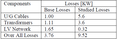 |
| a) The losses found in THIRUVERKADU FEEDER is 128 KW including all elements. |
| b) The maximum loss is found in the transformers. Transformers have maximum losses of 8.9 KW. |
| c) The average power factor is 0.9. |
| d) The losses issimulated with the standard values. |
| e) The maximum loss in a cable is10.3 KW. |
| f) The maximum line loss is 0.8. |
CONCLUSION |
| In this paper we studied about the technical and nontechnical losses in distribution system. in the technical losses the flow of current through cables causes the loss and in non-technical it will be caused by inaccurate meters, improperly read meters, unauthorized connections as well as administrative errors. as we see the transformer, its efficiency depends upon the operating load.it has two type of losses: no-load loss and load loss. no-load loss is also called core loss & it occurs when the transformer is energized, it does not vary with load. Load loss is called as copper loss & it is the power loss on primary and secondary windings .we can reduce the losses by locating the transformer closed to the load centre. The additional energy needs to be produced and transferred to cover the technical losses. By installing the capacitor bank, resizing of conductors, shortening the distances and by phase balancing, the losses can be reduced. |
ACKNOWLEDGEMENT |
| First of all we would like to thank almighty who gave us strength and good thoughts for our life. We would repay our regards to our parents who are not less than a god to us. |
| We would like to express our deep gratitude to our Head of department Er. L. Ramesh Sir for his constant encouragement and positive talks to go for a paper presentation. We would also like thanks our project guide Dr. V. Ganesan sir who was always behind us at any instance and gave his suggestions and teachings which was a base for our paper. We would also like to thank our project coordinator Dr. K. Sujatha who were always ready to help us at any point at any time. At last but not the least we would like to thank our friends for their constant support. |
References |
|