ISSN ONLINE(2278-8875) PRINT (2320-3765)
ISSN ONLINE(2278-8875) PRINT (2320-3765)
Dr. A.J. Patil1, Rajesh R. Karhe2, Mahesh S.Patil3
|
| Related article at Pubmed, Scholar Google |
Visit for more related articles at International Journal of Advanced Research in Electrical, Electronics and Instrumentation Engineering
Home automation is an application of ubiquitous computing in which the home environment is monitored by ambient intelligence to provide context-aware services and facilitate remote home control. This paper discusses the approach of real-time system development using the data acquisition tool of LabVIEW. The system can monitor the temperature, humidity, lighting, fire & burglar alarm, gas density of the house and have infrared sensor to guarantees the family security. The approach combines hardware and software technologies. Virtual instrumentation uses a general-purpose computer to mimic real instruments with their controls and displays.
Keywords |
| ATmega16, Data acquisition, GSM, LabVIEW, Home Automation, Sensors. |
INTRODUCTION |
| The home automation system is a key for energy conservation that can be equipped in normal buildings. Now-a-days the demand for home automation systems in homes and offices are invariably increasing. These systems directly work on the household appliances and provide effortless operation and control of the devices[2]. In this paper we have presented the concept of smart home automation in an effort to reduce the energy consumption and wastage using advanced graphical software called LabVIEW. It provides the programming tools to code power system applications more easily, which saves programming time. With the development of low cost electronic components home automation migrated from being an industrial application to home automation. The home automation, our point of concern deals with the control of home appliances from a central location.[2] |
| A smart home is a space or a room which is provided with the ability to get accustomed by itself to certain situations to make the occupants feel comfortable. This smart home control system provides both less expensive home environment, as well as a great level of flexibility and control for the building administrators and great comfort for the occupants. |
SYSTEM CONFIGURATION |
| The overall block diagram of the system is shown in figure 1. Here AVR Atmega16 microcontroller is used to acquire data from different types of sensors.GSM modem is used to get the real time information of different parameters like temperature, humidity, and lighting system when we are outside the home and without any computer system with us. It can also be used for wireless communication. The system is categorised into four modules explained below.[6] |
| 1. Basic Module: It consists of temperature sensor, humidity sensor and a relay circuitry. LM35 temperature sensor is used because it does not require any external calibration or trimming to provide typical accuracies of ±1/40C at room temperature and ±3/40C over a full -55 to +1500C temperature range. Humidity sensor module SY-HS-220 is used which convert the relative humidity to the output voltage. |
| 2. Lighting System: The presence of light can be detected by using LDR (Light Dependent Resistor) sensor. It is a type of semiconductor and its conductivity changes with proportional change in the intensity of light. |
| 3. Fire Alarm System: The fire alarm system is designed to detect the unwanted presence of fire by monitoring environmental changes associated with combustion. In general, a fire alarm system is classified as either automatically actuated, manually actuated, or both. Automatic fire alarm systems are intended to notify the building occupants to evacuate in the event of a fire or other emergency, report the event to an off-premises location in order to summon emergency services, and to prepare the structure and associated systems to control the spread of fire and smoke. We used a smoke detector, a temperature sensor and a solenoid valve for water. |
| 4. Burglar Detection System: A burglar alarm is a system designed to detect intrusion–unauthorized entry into a building or home. Infrared sensors are used within the system. |
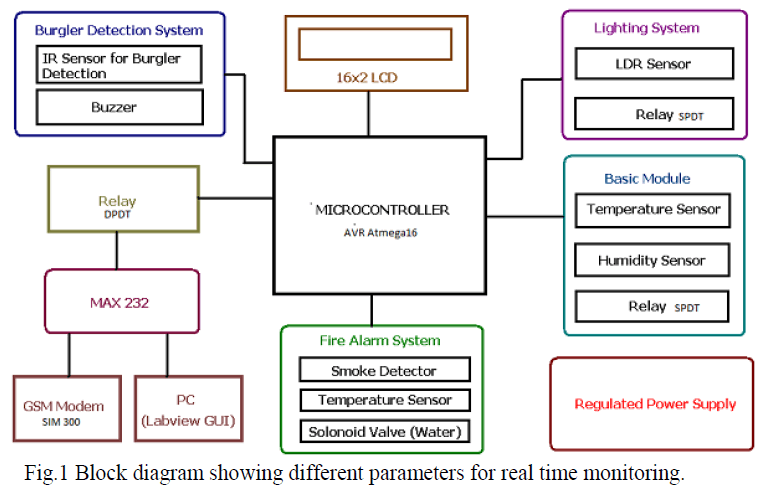 |
| Real time monitoring of different parameters can be displayed on 16×2 LCD display. All the parameters from different sensors are acquired on LabVIEW GUI (Graphical User Interface)[9]. |
| LabVIEW (Laboratory Virtual Instrumentation Workbench) software is a highly productive development environment that engineers and scientists use for graphical programming and unprecedented hardware integration to rapidly design and deploy measurement and control systems. Within this flexible platform, engineers scale from design to test and from small to large systems while reusing IP and refining their processes to achieve maximum performance. LabVIEW is a graphical programming platform that helps engineers scale from design to test and from small to large systems. It offers unprecedented integration with existing legacy software, IP, and hardware while capitalizing on the latest computing technologies. LabVIEW provides tools to solve today’s problems—and the capacity for future innovation—faster and more effectively. |
HARDWARE IMPLEMENTATION |
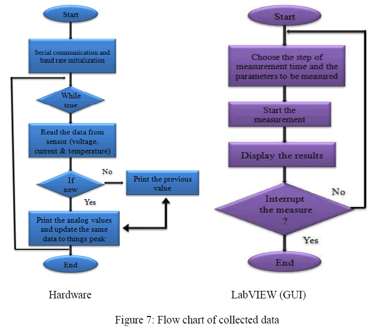
| Real time parameters are monitored using the communication between hardware and software through microcontroller and GSM. We have an option of NI-DAQ card that interfaces the sensor output directly to the computer but here we are using a serial port communication via AVR Atmega16 microcontroller. |
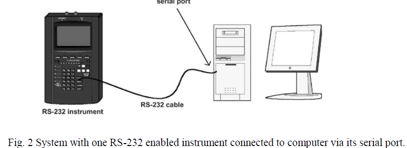
| 1. Communication using the serial port: LabVIEW can perform serial communication (either RS-232, RS-422, or RS-485 standards) using built-in or externally attached (for example, USB serial adaptors) serial ports on your computer.Serial communication uses a transmitter to send data one bit at a time over a single communication line to a receiver. You can use this method when data transfer rates are low, or when you must transfer data over long distances. The old-fashioned serial communication protocol, RS-232, is slower and less reliable than the GPIB, but you do not need a board in your computer to do it, your instrument does not need to conform to the IEEE 488 standard, and many devices still work with RS-232. Figure 2 shows a typical serial communication system[7]. |
 |
| Serial communication is handy because most PCs have one or two RS-232 serial ports built in you can send and receive data without buying any special hardware. Some newer computers do not have a built-in serial port, but it is easy to buy a USB to RS-232 serial adaptor for about the cost of a USB mouse. Although most computers also now have USB (universal serial bus) ports built-in, USB is a more complex protocol that is oriented at computer peripherals, rather than communication with scientific instruments. Serial communication (RS-232, RS-422, or RS-485) is old compared to USB, but is still widely used for many industrial devices[12]. |
| Many GPIB instruments also have built-in serial ports. However, unlike GPIB, an RS-232 serial port can communicate with only one device, which can be limiting for some applications. Serial port communication is also painstakingly slow and has no built-in error-checking capabilities. However, serial communication has its uses (it is certainly economical), and the LabVIEW Serial library contains ready-to-use functions for serial port operations. If you have a cable and a device to "talk" to, you are all set to try out serial communication. |
| 2. Data Acquisition System: Data acquisition, or DAQ for short, is simply the process of measuring a real world signal, such as a voltage, and bringing that information into the computer for processing, analysis, storage, or other data manipulation. Physical phenomena represent the real-world signals you are trying to measure, such as speed, temperature, humidity, pressure, flow, pH, start-stop, radioactivity, light intensity, and so on. You use sensors (sometimes also called transducers) to evaluate the physical phenomena and produce electrical signals proportionately. For example, thermocouples, a type of sensor, convert temperature into a voltage that an A/D (analog to digital) converter can measure. Other examples of sensors include strain gauges, flow meters, and pressure transducers, which measure displacement in a material due to stress, rate of flow, and pressure, respectively. In each case, the electrical signal produced by the sensor is directly related to the phenomenon it monitors. LabVIEW can command DAQ devices to read analog input signals (A/D conversion), generate analog output signals (D/A conversion), read and write digital signals, and manipulate the on-board counters for frequency measurement, pulse generation, quadrature encoder measurements, and so on, to interface with the transducers. In the case of analog input, the voltage data from the sensor goes into the plug-in DAQ devices in the computer, which sends the data into computer memory for storage, processing, or other manipulation[10]. |
| Data Acquisition System consists of a microcontroller and a sets of sensors connected through the existing digital inputs as well as through the analog inputs which has a resolution of 10-bit ADC. |
| GSM SIM-300 Module Interfacing: |
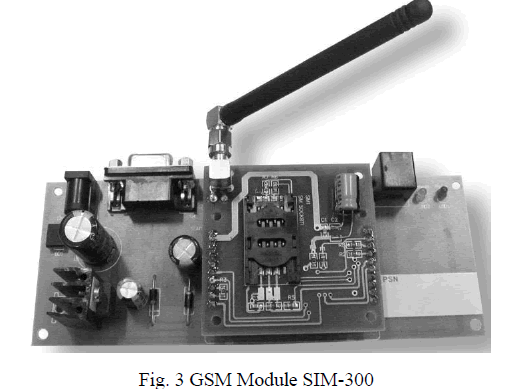
| SIM300 is a Tri-band GSM/GPRS module that operate on frequencies 900 MHz to 1900 MHz, SIM300 can use in many application, such as Smart phone, PDA phone and other mobile device. The physical interface to the mobile applications made through a 60 pins board-to-board connector, which provides all hardware interfaces between the module and customersâÃâ¬ÃŸ boards except the RF antenna interface. SIM300 Specifications: |
| Two serial ports to interface with Microcontrollers or PCs |
| Two audio channels include two microphones inputs and two speaker outputs. |
| This can easily configure by AT command. |
| SIM300 provide RF antenna interface with two alternatives: antenna connector and antenna pad. |
 |
| The SIM300 is designed with power saving technique, the current consumption to as low as 2.5mA in SLEEP mode The SIM300 integrated with extended TCP/IP AT commands. |
| Real time clock DS1308: |
| The DS1308 Serial Real Time Clock is a low power, full BCD clock/calendar plus 56 bytes of non-volatile SRAM. Address and data transferred serially via a 2–wire bi–directional bus. The clock/calendar provides seconds, minutes, hours, day, date, month, and year information. The end of the month date automatically adjusted for months with less than 31 days, including corrections for leap year. The clock operates in either the 24–hour or the 12–hour format with AM/PM indicator. The DS1308 has a built–in power sense circuit that detects power failures and automatically switches to the battery supply. |
EXPERIMENTAL ANALYSIS |
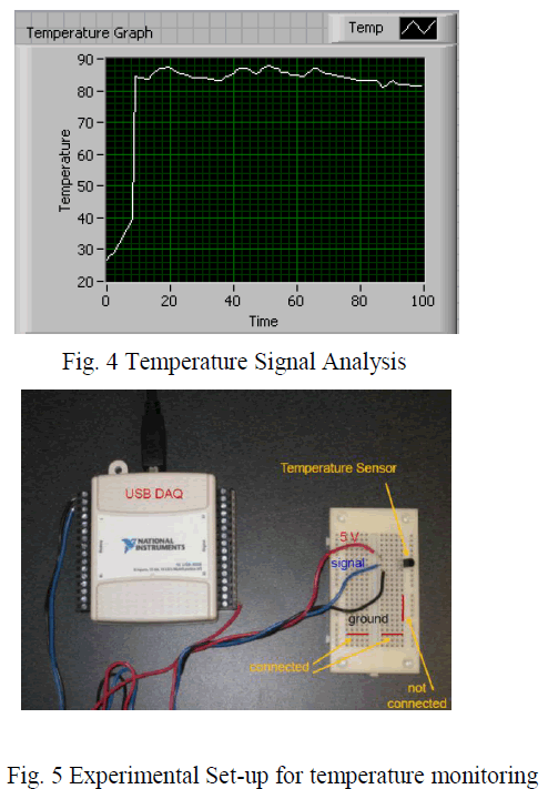
| Temperature signal can be easily analysed using NI USB6008 DAQ device. The steps we will follow are: |
| Configure the DAQ device in the Measurement & Automation Explorer (MAX). Open LabVIEW. |
| Create the DAQ Assistant on the block diagram window. |
| Configure the measurement. |
| Create the conversion equation from volts to ºC on the block diagram window. |
| Create the chart indicator on the front panel window. |
| Wire the DAQ Assistant, conversion equation, and chart indicator. |
| Save and run the program. |
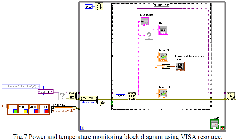
| Figure 4 shows the real time variation of temperature on front panel while figure 5 shows experimental set-up for temperature monitoring. In the next stage we can reduce the system cost by replacing DAQ device. We used serial line communication through ATmega16 microcontroller. In this application commands are given through GUI and transmitted through serial port interface. First the VISA configures serial port VI is initialized, where different serial port parameters are specified. Then the serial port read and writes units are activated[9]. |
 |
RESULTS AND DISCUSSIONS |
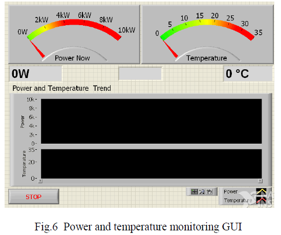
| The system has been implemented, tested successfully and achieved reliable transmission of data to the remote site and representation of waveform along with logging of data in excel sheet using LabVIEW. Acquired data display at each node and sent to master processor that compile the acquired information and send to remote location using GSM technology and simultaneously display and log into spreadsheet the variations in quantity under measurement to local and remote system configured with LabVIEW platform. Figure 6 shows the parameters monitoring on LabVIEW GUI. It shows the power and temperature monitoring. Actual code using VISA flush input-output function and VISA close function[9]. The VISA Configure Serial Port VI initializes the port identified by VISA resource name to the specified settings. Timeout sets the timeout value for the serial communication. Baud rate, data bits, parity, and flow control specify those specific serial port parameters. |
 |
 |
CONCLUSION |
| We address a new smart home control system based on sensor networks to make home networks more intelligent and automatic. We implement the proposed system and develop related hardware and software. We suggest new ubiquitous home scenarios based on the proposed system. We expect that our work contributes towards the development of ubiquitous home networks. Energy savings and user happiness are two major design considerations for modern home automation systems. |
| The application was designed and developed to prove a couple of concepts about the data acquisition in general and some notions about the possibility of adding remote controlling/monitoring. This has a teaching purpose: it is being used for a series of experiments between several laboratories, at the moment. From one point of view one can process the experimental data gathered from a real process, but one can also see the result of one remote command sent to industrial equipment in the real time. |
 |
References |
|