ISSN ONLINE(2278-8875) PRINT (2320-3765)
ISSN ONLINE(2278-8875) PRINT (2320-3765)
| B.Vamsi Krishna Associate Professor, Bharath University, Chennai-600073, India |
| Related article at Pubmed, Scholar Google |
Visit for more related articles at International Journal of Advanced Research in Electrical, Electronics and Instrumentation Engineering
The aim of this paper is to describe work involved in investigations on the implementation of single phase matrix converter (SPMC) as an AC-AC converter subjected to passive load conditions. The successful implementation of the SPMC had been conceived, designed and realized by synthesizing the output using the well - known sinusoidal pulse width modulation (SPWM) technique with IGBTs as power switching devices. To show the validity of results, Simulations were done by means of the power system block within the MATLAB/ SIMULINK software package.
INTRODUCTION |
| Matrix converter has been known to offer an "all silicon" solution for AC-AC Conversion, removing the need for reactive energy storage components used in conventional rectifier-inverter based system .Its topology was first proposed by Gyugyi in 1976. The circuit is arranged such that any output lines of the converter can be connected to any input lines. The main purpose of this paper is to describe the successful implementation of the SPMC that had been conceived, designed and realised by synthesizing the output using the well-known SPWM technique. |
THE SPMC |
| The SPMC requires 4 bi-directional switches each capable of conducting current in both directions, blocking forward and reverse voltages. The IGBTs were used as power switches which combines the positive attributes of BJTs and MOSFETs. BJTs have lower conduction losses in the on-state, especially in devices with larger blocking voltages, but have longer switching times, especially at turn-off while MOSFETs can be turned on and off much faster, but their on-state conduction losses are larger, especially in devices rated for higher blocking voltages. Hence, IGBTs have lower on-state voltage drop with high blocking voltage capabilities in addition to fast switching speeds. It is also popular amongst researchers that could lead to high-power applications with reasonably fast switching frequency for fine control. |
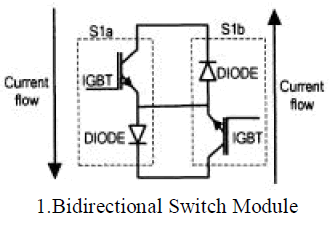 |
| The matrix converter is a forced commutated converter which uses an array of controlled bidirectional switches as the main power elements to create a variable output voltage system With unrestricted frequency. It does not have any dc link circuit and does not need any large energy storage elements. The matrix converter has several advantages over traditional rectifier-inverter type power frequency converters. It provides sinusoidal input and output waveforms, with minimal higher order harmonics and no subharmonics; it has inherent bi-directional energy flow capability; the input power factor can be fully controlled. Last but not least, it has minimal energy storage requirements, which allows to get rid of bulky and lifetime-limited energy-storing capacitors. The key features of matrix converter are Simple and compact power circuit, Generation of load voltage with arbitrary amplitude and frequency, Sinusoidal input and output currents, Operation with unity power factor for any load, Regeneration capability. |
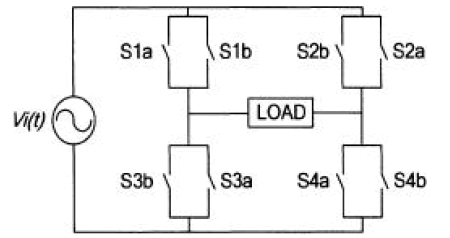 |
SPMC Circuit Configuration |
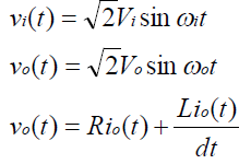
| The input and output voltage of SPMC is given by (1) and (2) respectively with loads represented in (3), |
 |
SWITCHING STRATEGIES: |
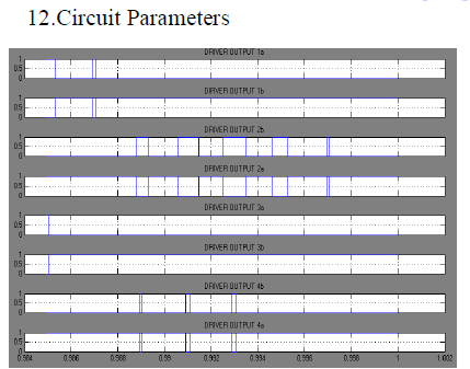
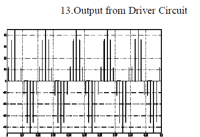
| Driver circuits are designed to generate the SPWM patterns that are used to control the power switches, comprising IGBTs in the SPMC circuit. The switching angles, of the 4 bidirectional switches sij (i = 1,2,3,4 and j = a , b)where 'a' and 'b' are representing driver one and two respectively. |
| The following rules are then applied; |
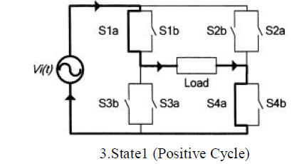
| 2.1.1 At any time't', only two switches sij (i = 1, 4 and j = a) will be in 'ON' state and conduct the current flow during positive cycle of input source (state 1) |
 |
| 2.1.2 At any time't' only two switches sij (i = 1, 4 and j = b) will be in 'ON' state and conduct the current flow during negative cycle of input source (state 2). |
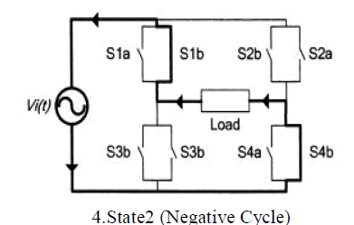 |
| 2.1.3 At any time't' only two switches Sij (i = 2, 3 and j = b) will be in 'ON' state and conduct the current flow during positive cycle of input source (state 3). |
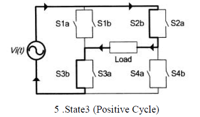 |
| 2.1.4 At any time't' only two switches sij (i = 2, 3 andj = a) will be in 'ON' state and conduct the current flow during negative cycle of input source (state 4) |
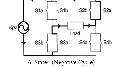 |
SEQUENCE OF SWITCHING CONTROL: |
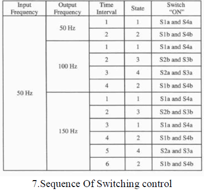
| The output frequency is synthesized in multiples of input frequency of 50Hz (say 50Hz, 100Hz and 150Hz). The sequences of switching are dependent on the time interval and state of the driver circuit. |
| Consider the output frequency is 50 Hz. To achieve this,when the supply voltage is positive the switch is in state 1(Sla and S4a are turned ON). On the other hand switching state 2 are used during negative cycle to produce the next half Cycle |
 |
SINUSOIDAL PULSE WIDTH MODULATION |
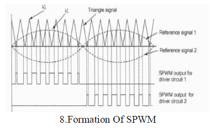
| The sinusoidal pulse width modulation is commonly used in industrial applications. The Sinusoidal Pulse Width Modulation (SPWM) is a well known wave shaping technique in power electronics. For realisation, a high frequency triangular carrier signal, Vc, is compared with a sinusoidal reference signal, Vr of the desired frequency. The crossover points are used to determine the switching instants.The magnitude ratio of the reference signal (Vr) to that of the triangular signal (Vc) is known as the modulation index (mi). The magnitude of fundamental component of output voltage is proportional to mi. The amplitude Vc of thetriangular signal is generally kept constant. By varying the modulation index, the output voltage could be controlled.The frequency of reference signal fr determines the inverter output frequency fo, and its peak amplitude Ar controls the modulation index M, and then in turn the RMS output voltage Vo. The number of pulses per half cycle depends on the carrierfrequency. |
 |
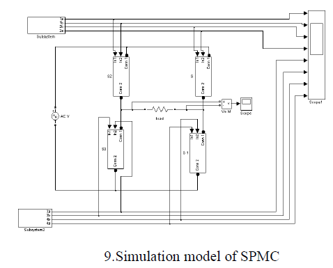
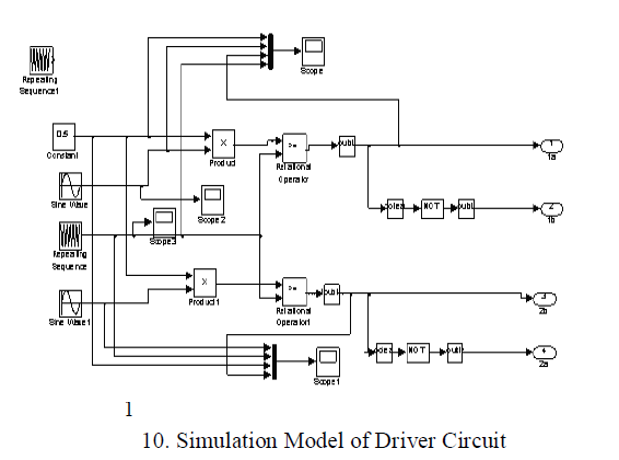
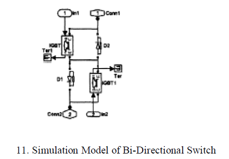
| Main model of SPMC consists of bidirectional switch module and driver circuits. The multiplier unit in the driver circuit is used to vary the magnitude of the sampled sinusoidal reference signal in order to change the modulation index of the SPWM. The modulation index input data is in the form of and integer ranging from 1 to 10. The output from the multiplier unit will then be used to compare with the carrier signal, thus producing the required SPWM switching signal. |
| The MATLAB model of the SPMC was developed by using the sim power system block set. Bidirectional switch module is developed by interconnecting two IGBT’s. Computer simulation of SPMC is done using MATLAB SIMULINK and the corresponding results for R and RL load are obtained. Simulation parameters are explained in the table. Figure shows the developed model for SPMC by using MLS that performs the operation of a direct AC-AC converter. |
 |
 |
 |
SIMULATION RESULTS |
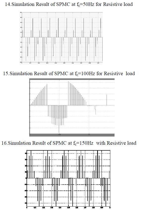
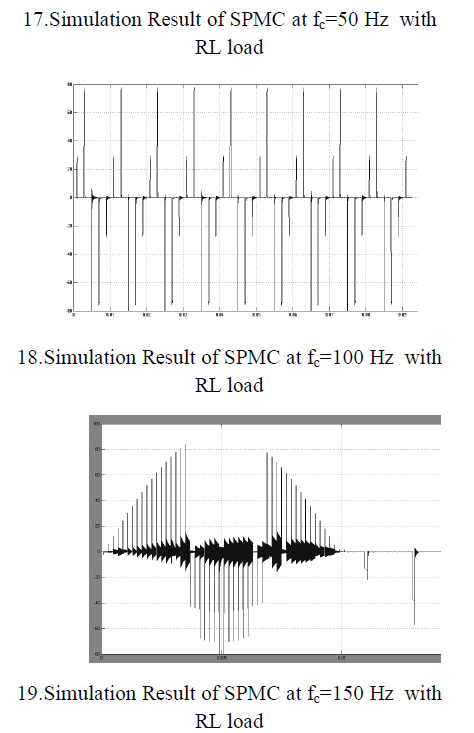
| The SPMC was simulated with switching strategy being implemented on all the four states and the results of SPMC model are shown in the below figures for 50Hz, 100Hz, 150Hz, that were synthesized from a supply operating at fundamental frequency of 50Hz. The simulation model could be used to study the behavior of the SPMC as an AC-AC converter under a variety of operating conditions, including different reference frequency. |
 |
 |
 |
 |
 |
CONCLUSION |
| In this paper, a single-phase to single phase matrix converter with passive load condition and its advantages against the commercial devices were presented. The SPMC circuit is designed and simulated which does not require the dc link as in the conventional model. The simulated output waveforms show the successful implementation of the SPMC circuit in the MLS Software. These simulated results of SPMC illustrates that it is feasible to realize the matrix converter as a frequency step-up converter. Further works are required to implement low-pass filter at the output to ensure continuous waveforms that are desirable in actual applications. Also when using with RL load, Undesirable spikes seem to appear with a reasonable degree of magnitude that requires elimination. This probably could be solved using novel commutation strategies. |
References |
|