ISSN ONLINE(2278-8875) PRINT (2320-3765)
ISSN ONLINE(2278-8875) PRINT (2320-3765)
| A.Mohandoss1, K.Sivaramachandran2, S.Ashwin karthik3, S.Murugan4 P.G. Scholar, Department of EEE, R.V.S. College of Engineering and Technology, Coimbatore, India |
| Related article at Pubmed, Scholar Google |
Visit for more related articles at International Journal of Advanced Research in Electrical, Electronics and Instrumentation Engineering
In this proposed methodology a Hybrid power system combining the PV Module, wind energy source and a battery source to supply remote areas more effectively. This hybrid system synchronizes the PV module, battery and wind source using a modified bidirectional multi input dc-dc boost converter. This converter drive load and utilize the power generated from the hybrid power system more efficiently. This Hybrid power system by definition contain a number of power generation devices such as wind turbines based energy sources, photovoltaic source, micro-hydro and also fuel generators as input sources for power generation. However the proposed three input boost converter is applied to hybridize a PV, WIND energy, and a battery storage scheme. Four liberated duty ratios of the converter facilitate power flow between input sources and the load. This converter has the merits of making use of a low voltage battery. The inherent nature of this converter eliminates the need for separate input filters for PFC. The multi –input converter providing simple circuit topology, centralized control of power flow is bidirectional in this converter.
Keywords |
| Solar PV module, wind Energy System, Battery, Three Input Bidirectional Boost Converter. |
INTRODUCTION |
| Hybrid power systems are planned for the generation of electrical power more efficiently. They are usually liberated of bulky centralized electric grids and are used in remote zones. Hybrid power systems by explanation contain a number of power generation strategies such as wind turbines, photovoltaic module, and micro-hydro and fossil fuel originators. However this hybrid power schemes ranges from small systems planned for one or several homes to very large ones for remote island grids or large communities Hybrid power systems are seen as a way to deliver power to the many remote societies in the emergent world where the expenditures for large scale enlargement of electrical grids are prohibitive and the transportation costs of diesel fuel are also very high. The usage of renewable power generation systems diminishes the use of expensive fuels, permits for the cleaner generation of electrical power and also expands the standard of living for many people in remote areas. |
| Hybrid energy systems combine multiple energy generation or storage technologies to build an electricity generation system that optimizes the characteristics of the individual generation sources. For example, PV hybrid systems usually combine photovoltaic (PV) generation of electricity with energy storage (classically a rechargeable battery) and a fossil fuel engine generator. PV generators have no fuel costs, produce no greenhouse gases or other air contaminants, are quiet and require minimal maintenance, but they have relatively high capital cost and produce power intermittently, depending on the amount of sunlight available (they are non-dispatch able). By optimizing the size of the PV array, the battery, and the gen set and through proper control strategy, an economic compromise between the capital cost of the PV array and the battery and the operating cost and emissions of the gen-set can be achieved. |
| Wind hybrid power systems combines wind turbines with other storage and/or generation sources. Wind and its generation potential are inherently variable. The combination has been described as particularly suited to islands that are not connected to larger grids. Wind power is a very efficient source of energy in areas that are invariably windy. Typical high wind regimes occur in areas of low-priority land use and collection area is perpendicular to the ground surface and occupies only a small fraction of the area from which the energy is captured. Wind power has many benefits including the facts that it produces virtually no pollution of air, water or soil; it is renewable (non-delectable). |
RELATED WORK |
| Photovoltaic (PV) energy appears quite attractive for electricity generation because of its soundless, pollution-free, scale elasticity, and little preservation. Because of the PV power generation necessity on sun treatment level, ambient temperature, and erratic shadows, the PV-based power system should be accompanied by other another energy sources to ensure a reliable power supply. This traditional method deals with two types of MICs: in the first type, only one power source is permitted to transfer energy to the load at a period. Similarly in the second category, all the input sources can distribute power to the load either separately or concurrently. Traditional methods that participate different power sources to form a hybrid power system can be classified as ac-coupled systems. However, the main shortcomings of these traditional assimilating methods are multifaceted scheme topology, high count of plans, high power victims, expensive cost and bulky. However in recent years, numerous power conversion steps used in traditional hybrid schemes are swapped by multi-input converters (MICs), which syndicate different power sources in a single structure. |
| AC – Coupled arrangement having complex structure ,number of device are enlarged as well as the increase of input sources ,the control technology used in ac- coupled is more expensive compare to other system size is great. So it is not appropriate for smart hybrid power system. Similarly this ac-coupled substituted by multi-input converter. |
PROPOSED HYBRID POWER SYSTEM MODEL |
| Hybrid Power Systems incorporate several electricity generating components with usually one major control system which enables the system to supply electricity in the required quality .Components for electricity generation can utilize renewable energy sources like wind turbines, photovoltaic, and battery. In our project three input sources hybridizing with dc-dc boost converter. As an interesting application of the proposed converter, the input ports are mainly conceder to interface a PV sources and an wind energy a battery as the storage element .This system achieving maximum power of PV sources and regulating the output voltage . However this regulated output voltage use to ensure the reliable power supply to dc load .This converter also able to achieving maximum boost efficiency. The PV – hybrid power system, which is a combination of a photovoltaic array, with wind energy, battery, offers a reliable electricity production system. New three-input dc–dc boost converter is proposed for hybrid power system applications. |
A. Block Diagram of Proposed Model |
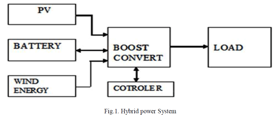 |
| Fig.1.illustrates the block diagram of hybrid power system with multi input converter with various input sources. The modified boost converter interfaces two unidirectional ports for input sources, and a bidirectional port for storage Component and a port for output load in an integrated assembly. However this converter is current-source type at the both input power ports and also able to step up the input voltages. This arrangement consumes only four power switches that are independently controlled with four different duty ratios. |
B. Conventional A.C. Coupled System |
| SMA Solar Expertise began emerging ac-coupling system platforms using its inverter products in the 1990s. In the years that followed, SMA continued to develop and refine its products and integrated approach to ac coupling. AC – Coupled system having complex system topology ,number of device are enlarged as well as the increase of input sources ,the control technology used in ac- coupled is more costly compare to other system size is large so it not suitable for smart hybrid power system this ac-coupled replaced by multi-input converter. |
C. Multi Input Converter |
| An innovative topology for multiple energy source conversion is offered. The topology is capable of interfacing sources of different voltage-current features to a common load, while accomplishing a low part count. A fixed frequency switching approach is investigated and the resulting operational modes are analysed. . The multi –input converter providing simple circuit topology, unified control of power flow bidirectional, high reliability and low cost compare to ac coupled structure. Two multiple-input converters based on flux additively in a multi winding transformer are reported. Because there was no possibility of bidirectional operating of the converter , and complexity of driving circuits and output power limitation in, they are not suitable for hybrid systems, a three-port bidirectional converter with three energetic full bridge circuit, additional two series-resonant tank circuit, and also a three winding highfrequency transformer are projected. In association with three-port circuits in addition with inductors and Diode Bridge circuit at the load end, it stretches higher boost gain and compact switching losses because of soft-switching operation. |
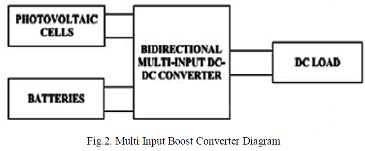 |
| Fig.2.shows the diagram of multi input boost converter converted with the load. It uses the input sources as PV source, wind energy source and battery as input. |
SOLAR ENERGY AND WIND ENERGY |
A. PV Module |
| The growing concern of global warming and the depletion of fossil fuels reserves, several are looking at sustained energy solution to preserve the earth for the future generation. So now going to yield the electrical energy by using of renewable sources like solar, battery and wind .for my work I used the boost converter with MPPT control to attain the maximum power. Photovoltaic is the field of technology and research associated to the practical of photovoltaic cells in generating electricity from light, through it is often used to refer to the generation of electricity from sunlight. |
B. Solar V-I Characteristics |
| Each solar cell has its own voltage-current characteristics. Figure shows the v-i characteristic of a typical photovoltaic cell. The difficult with extracting the most possible power from a solar panel is due to non linearity of the characteristics curve. The characteristic shows two curves, one shows the behaviour of the current with respect to increasing voltage. The other curve is the power voltage curve and is obtained by the equation (P=VI). |
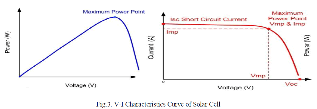 |
| Fig.3. illustrates the maximum power point curve with power in the y-axis and the voltage in the x-axis. Similarly another graph with current in y-axis and voltage in x-axis of . This is called V-I characteristics of a solar cell. |
C. Wind Energy System |
| Wind is a form of solar energy. Winds are initiated by the uneven heating of the atmosphere by the sun light, the abnormalities of the earth's surface, and rotation of the earth. Wind flow shapes are improved by the earth's landscape, forms of water, and vegetative cover. This wind flow, or motion energy, when "harvested" by modern wind turbines, can be used to produce electricity. Wind turbines, like aircraft propeller blades, effort in the moving air and power an electric generator that supplies an electric power. Simply identified, a wind turbine is the differing of a fan. |
D. Battery |
| Battery is a device consisting of one or more electrochemical cells that transform stored chemical energy into electrical energy as output. It comprises of a number of voltaic cells; every voltaic cell involves of two half-cells connected in sequence by a conductive electrolyte enclosing anions and captions. One half-cell comprises electrolyte and the electrode to which anions (negatively charged ions) drift, the anode or negative electrode; the other half-cell embraces electrolyte and the electrode to which captions (positively charged ions) drift, the cathode or positive electrode as well. |
DC-DC BOOST CONVERTER |
| As specified in the introduction, the maximum power point tracking is essentially a load matching is difficult. However to adjust the input resistance of the panel to tie the load resistance (by varying the duty cycle ratio), a DC to DC converter is necessary. It has been considered that the efficiency of the DC to DC converter is extreme for buck converter, then for a buck-boost converter and least for a boost converter but as we propose to use our system whichever for keying to a grid or for a waste pumping structure which entails 230 V at the output end, so we proposes a boost converter. |
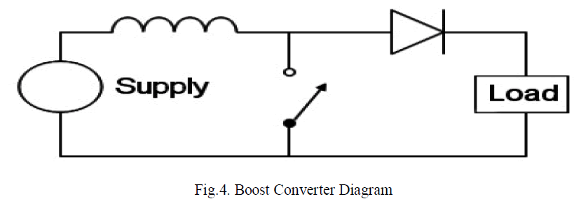 |
| Fig.4. illustrates the functional block diagram of a boost converter. It is step up DC-DC converter. The inductor in the input side act as a boost inductor . |
RESULT AND DISCUSSION |
| In this proposed system the PV module, wind energy and battery are synchronized to propose hybrid power system. Three input DC-DC boost converter supplies to the load from the hybrid power system. The MAT LAB is used to analyse the proposed hybrid power system model. |
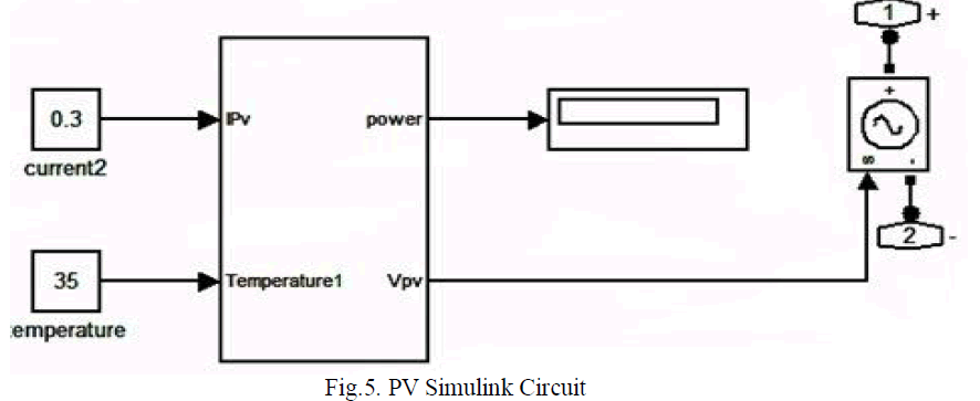 |
| Fig.5.describe the PV Simulink circuit of the solar cell. The current value and temperature value are mentioned in this PV Simulink circuit. The MATLAB simulation tool is used here. |
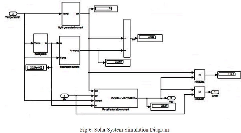 |
| The Fig.6.establishes the simulation diagram of photovoltaic system. It is one of the sources of multi input boost converter. |
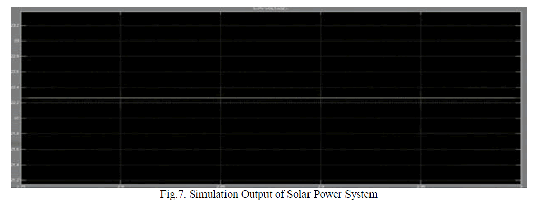 |
| The figure.7 explains the output stimulation diagram for the photovoltaic system. This the source voltage obtained from the PV system. |
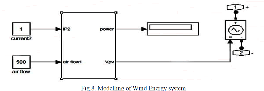 |
| The Fig.8 demonstrates the simulation diagram for the Wind energy system. The wind is available in nature it is also a renewable energy sources as solar energy system. So it is considered as one of the source for our hybrid power system. |
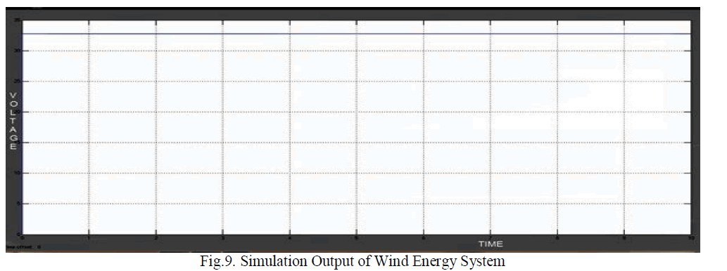 |
| The Fig.9 demonstrates the output simulation output waveform of wind energy system. Similarly it is also a source as solar energy system for this proposed system. |
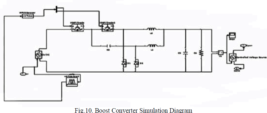 |
| The Fig.10 explains the mat lab simulation diagram of bidirectional multi input boost converter system. This boost converter has three input as considered in the suggested system. |
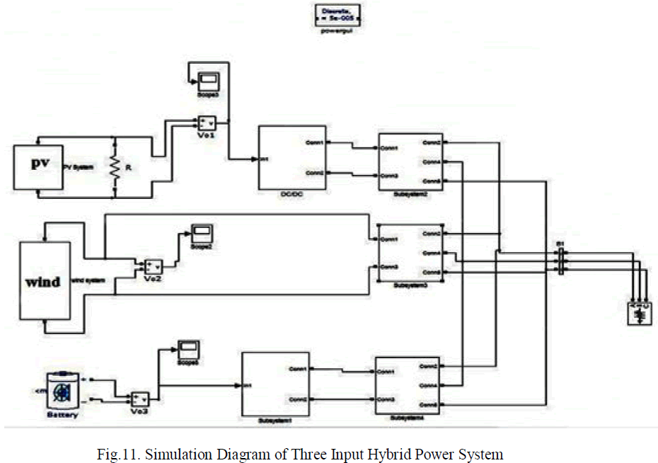 |
| The Fig.11 demonstrates the mat lab simulation diagram for the hybrid power system. The system is hybrid because of improved efficiency and reliability of the system is high. |
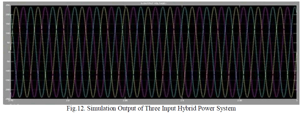 |
| Fig.12. illustrates the simulation output of hybrid power system with multi input boost converter. This output wave form explains the system response as well. |
CONCLUSION |
| The proposed small scale hybrid PV-wind and battery, generation systems, a supervisory controller, which manages the modes of operation and the power flow in the power system, was proposed, this controller was designed to operate in conjunction with newly developed local controllers. The PV – hybrid power system, which is a combination of a photovoltaic array, with wind energy, battery, offers a reliable electricity production system. PV – hybrid power systems are often the best solution to electrification of remote areas. In the design and sizing of the system we assume that the system is an autonomous. Such a constraint leads to an infinite number of possible system configurations the system modes and states were designed to provide system equilibrium conditions, and the appeal of the modes were held in specific constraints. Hence the output of the hybrid system tested using MAT LAB simulation tool. |
References |
|