ISSN ONLINE(2278-8875) PRINT (2320-3765)
ISSN ONLINE(2278-8875) PRINT (2320-3765)
Farzad Mohajeri1 and Zeinab Danesh2
|
| Related article at Pubmed, Scholar Google |
Visit for more related articles at International Journal of Advanced Research in Electrical, Electronics and Instrumentation Engineering
Propagating surface waves in array microstrip patch antennas causes some problems such as mutual coupling and scan blindness.Electromagnetic band-gap (EBG) structures are the form of periodic structures that in a certain frequency band suppress propagating surface waves. A new EBG structure terminated as step EBG structure is introduced in this paper.Primarily , the frequency band-gap of mushroom-like EBG is exhibited graphicly .Afterward its application between two microstrip patch antennas is explained. Then the step EBG structure is compared with traditional structure.A computer model is developed, applying HFSS software.The satisfactory results of the mentioned model also are shown as monograph
Keywords |
| mutual coupling , EBG , mushroom-like |
INTRODUCTION |
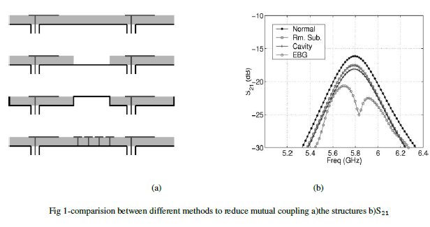
| There are different ways to reduce mutual coupling such as : removed substrate between antennas , cavity back microstrip antennas and the EBG structure between antennas. In fig 1 the mutual coupling between antennas are compared in different methods [1].As seen the reduction in EBG case is about 6dB lower than the other methods. |
 |
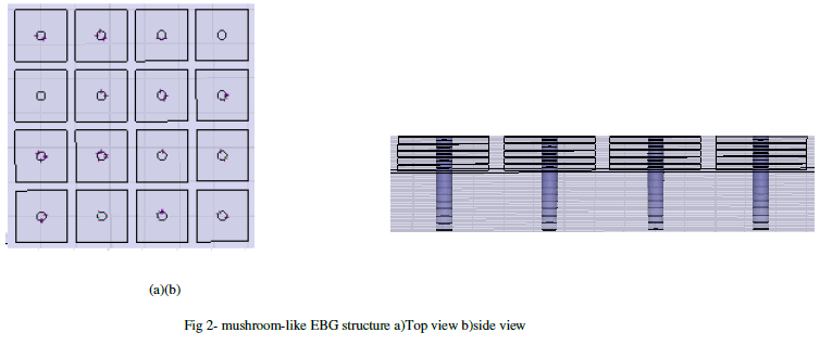
| The EBG structure has been suggested in [2] based on the photonic band-gap (PBG) phenomena in optics.Different forms of EBG structures are determined in [2],[3], but mushroom-like EBG structure is focused in this paper(fig 2). In the frequency band-gap the mushroom-like EBG structure suppresses propagating surface waves |
 |
| Depending on the size and gaps between patches in EBG, the height and permittivity of the substrate the frequency band-gap can be changed. Suppression of propagating wave results in increasing the antenna gain and reducing the mutual coupling in arrays [4-7]. |
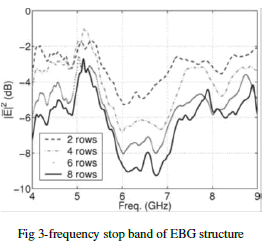
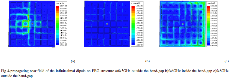
| In comparison with the propagating fields of an infinitesimal dipole source together and without the EBG structureProf.Rahmatsamii simulated and explored the effect of surface wave suppression. He applied the finite difference time domain (FDTD) method. For this purpose also he identified a frequency stop band for the field propagation (fig3). The author simulated the propagating near field inside and outside of the band-gap by HFSS (fig 4). To reduce mutual coupling between arrays , the patches resonance frequency should be in the stop band of the EBG structure. The characteristic of the band-gap are formulated in [1]. |
 |
 |
REDUCTION of MUTUAL COUPLING by STEP EBG STRUCTURE |
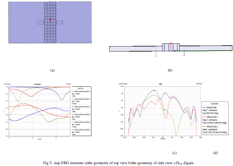
| This investigation results in increasing the height of the substrate under the EBG structure and reducing the distance between two patches. The height of the substrate under the patches is 2mm while, the height of the EBG structure increase to 3mm so, 5dB increase in antenna gain and 4dB reduction in mutual coupling is seen (fig 5). |
| More satisfaction results are obtained although the distance between two patches 15.8 cm reduces. |
| The resonance frequency of two antennas is around 6GHz that is in the stop band of the EBG structure. The patches are 4 in 7 mm , the height of the substrate under the patches is 2mm and dielectric constant is 10.2 . The size of the EBG patches is 3in3mm however, the gaps between them are 0.5mm. The radius of thevias is 0.259 mm. |
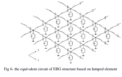
| The equivalent circuit of the EBG structure based on lumped element is shown (fig 6). The main idea is to increase the height of the EBG structure that results to increase the parallel impedance and finally increase the characteristic impedance in Γ formulation [8]. |
 |
 |
CONCLUSION |
| EBG structures are inserted between arrays to reduce mutual coupling. Increasing the height of the EBG structure with constant height of the substrate under the antenna patches the structure changes to step EBG structure, that results to reduction the S11 and S12 and increasing the antenna gain. |
References |
|